


 Loading...
VHF RADIOTELEPHONE
FM-8800D/8800S

9-52 Ashihara-cho,
Nishinomiya 662-8580, JAPAN
Telephone : |
0798-65-2111 |
|
Fax |
: |
0798-65-4200 |
All rights reserved. |
Printed in Japan |
Pub. No. OME-56420
( TATA ) FM-8800D/S
The paper used in this manual is elemental chlorine free.
FURUNO Authorized Distributor/Dealer
FIRST EDITION : SEP. 2004
E : DEC. 01, 2006
*00014993014*
*00014993014*
* 0 0 0 1 4 9 9 3 0 1 4 *
*OME56420E00*
*OME56420E00*
* O M E 5 6 4 2 0 E 0 0 *

CANCELING DISTRESS ALERT
If less than three seconds has elapsed since the [DISTRESS] key was pressed, the distress alert may be canceled by pressing the [CANCEL] key. Otherwise, do the following:
1.Switch off equipment immediately.
2.Switch equipment on and set to Channel 16.
3.Transmit message to “All Stations” giving your vessel's name, callsign and DSC number to cancel the distress alert.
Example message:
All Stations, All Stations, All Stations
This is VESSEL'S NAME, CALLSIGN,
DSC NUMBER, POSITION.
Cancel my distress alert of DATE, TIME, UTC.
=Master, VESSEL'S NAME, CALLSIGN. DSC NUMBER, DATE, TIME UTC.
i

 SAFETY INSTRUCTIONS
 WARNING
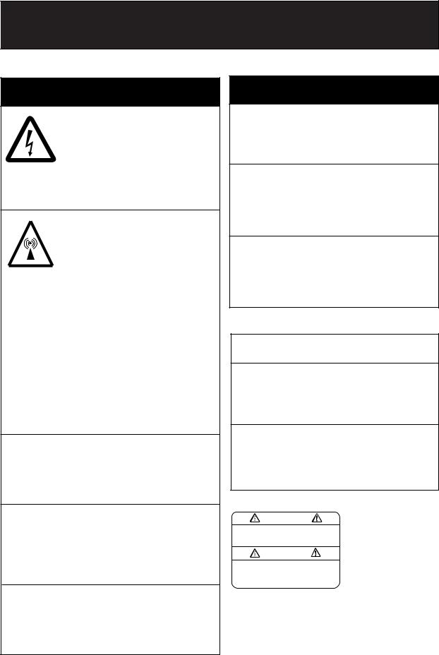
Do not open the equipment.
Hazardous voltage which can cause electrical shock, burn or serious injury exists inside the equipment. Only qualified personnel should work inside the equipment.
Do not approach the antenna closer than 0.9 m (MPE by FCC) when it is transmitting.
The antenna emits radio waves which can be harmful to the human body.
|
RF power density |
Distance |
Description |
|
on antenna aperture |
|
required by |
|
100 W/m 2 |
0.11 m |
IEC 60945 |
FM-8800S |
|
|
|
10 W/m2 |
0.33 m |
IEC 60945 |
|
|
2 W/m 2 |
0.9 m |
MPE by FCC |
|
100 W/m 2 |
0.11 m |
IEC 60945 |
FM-8800D |
10 W/m2 |
0.33 m |
IEC 60945 |
|
2 W/m 2 |
0.9 m |
MPE by FCC |
(MPE: Minimum Permissible Exposure)
Do not disassemble or modify the equipment.
Fire, electrical shock or serious injury can result.
Turn off the power immediately if water leaks into the equipment or the equipment is emitting smoke or fire.
Continued use of the equipment can cause fire or electrical shock.
Do not place liquid-filled containers on the top of the equipment.
Fire or electrical shock can result if a liquid spills into the equipment.
 WARNING
Do not operate the equipment with wet hands.
Electrical shock can result.
Keep heater away from equipment.
Heat can alter equipment shape and melt the power cord, which can cause fire or electrical shock.
Any repair work must be done by a licensed radio technician.
Improper repair work can cause electrical shock or fire.
 CAUTION
Do not touch any part of the antenna when the equipment is transmitting.
Electrical shock can result.
Use the proper fuse.
Use of a wrong fuse can result in fire or cause permanent damage to the equipment.
WARNING |
Terminal, Communication |
||
|
Unit |
|
|
To avoid electrical shock, do not |
|
|
|
remove cover. No user-serviceable |
Name: Warning Label (1) |
||
parts inside. |
Type: 86-003-1011 |
||
|
|||
|
Code No.: 100-236-231 |
||
ii
Important Notices
•No part of this manual may be copied or reproduced without written permission.
•If this manual is lost or worn, contact your dealer about replacement.
•The contents of this manual and equipment specifications are subject to change without notice.
•The example screens (or illustrations) shown in this manual may not match the screens you see on your display. The screen you see depends on your system configuration and equipment settings.
•This manual is intended for use by native speakers of English.
•FURUNO will assume no responsibility for the damage caused by improper use or modification of the equipment or claims of loss of profit by a third party.
iii
TABLE OF CONTENTS
|
|
|
|
.......................................................................................................FOREWORD |
vii |
||
SYSTEM CONFIGURATION................................................................................ |
ix |
||
SPECIFICATIONS........................................................................................... |
SP-1 |
||
1. OPERATIONAL OVERVIEW |
|
||
1.1 |
Controls Keys and LCD Indication............................................................................. |
1-1 |
|
|
1.1.1 |
Front panel...................................................................................................... |
1-1 |
|
1.1.2 |
Controls .......................................................................................................... |
1-2 |
|
1.1.3 Indications on the LCD.................................................................................... |
1-5 |
|
|
1.1.4 |
Audio alarms................................................................................................... |
1-6 |
1.2 |
VHF Basic Operation................................................................................................. |
1-7 |
|
|
1.2.1 Turning the power on and adjusting contrast................................................... |
1-7 |
|
|
1.2.2 |
Selecting channel modes, channels................................................................ |
1-7 |
|
1.2.3 |
Adjusting volume of loudspeaker .................................................................... |
1-8 |
|
1.2.4 |
Adjusting squelch............................................................................................ |
1-8 |
|
1.2.5 |
Transmitting .................................................................................................... |
1-8 |
|
1.2.6 |
Selecting output power ................................................................................... |
1-8 |
|
1.2.7 |
Turning the loudspeaker on/off........................................................................ |
1-8 |
|
1.2.8 Quick selection of CH16 ................................................................................. |
1-9 |
|
|
1.2.9 |
Dual watch...................................................................................................... |
1-9 |
|
1.2.10 Scanning......................................................................................................... |
1-9 |
|
|
1.2.11 Remarks on voice communications................................................................. |
1-9 |
|
1.3 |
DSC Operational Overview ..................................................................................... |
1-10 |
|
|
1.3.1 |
LED warnings ............................................................................................... |
1-10 |
|
1.3.2 |
DSC operational overview............................................................................. |
1-10 |
|
1.3.3 |
Automatic acknowledge on/off ....................................................................... |
1-11 |
1.4 |
Priority..................................................................................................................... |
1-12 |
|
2. DSC DISTRESS COMMUNICATION |
|
||
2.1 |
Distress Alert Transmission from the DISTRESS Key................................................ |
2-1 |
|
2.2 |
Distress Alert Transmission with Nature of Distress................................................... |
2-3 |
|
2.3 |
Distress Alert Transmission From CALL Key ............................................................. |
2-5 |
|
2.4 |
Canceling a False Distress Alert................................................................................ |
2-6 |
|
2.5 |
Receiving Distress Alert from Other Vessel, Transmitting DIST ACK Signal .............. |
2-7 |
|
2.6 |
Sending Distress Relay on Behalf of a Ship in Distress............................................ |
2-11 |
|
|
2.6.1 Sending distress relay to coast station........................................................... |
2-11 |
|
|
2.6.2 Sending distress relay to all ships ................................................................. |
2-13 |
|
2.7 |
Receiving Distress Relay......................................................................................... |
2-15 |
|
|
2.7.1 Receiving distress relay all call ..................................................................... |
2-15 |
|
|
2.7.2 Receiving distress relay from coast station ................................................... |
2-16 |
|
iv
TABLE OF CONTENTS
3. DSC OPERATION FOR NON-DISTRESS CASES
3.1 |
Coast or Ship Call ....................................................................................................... |
3-1 |
|
3.1.1 Sending a coast or ship call.............................................................................. |
3-2 |
|
3.1.2 Receiving acknowledgement of coast or ship call ............................................ |
3-4 |
|
3.1.3 Receiving a coast or ship call ........................................................................... |
3-5 |
3.2 |
Group Call ................................................................................................................. |
3-10 |
|
3.2.1 Sending a group call ....................................................................................... |
3-10 |
|
3.2.2 Receiving a group call .................................................................................... |
3-12 |
3.3 |
PSTN Call.................................................................................................................. |
3-13 |
|
3.3.1 Sending a PSTN call....................................................................................... |
3-13 |
|
3.3.2 PSTN call disconnection (ship disconnects line) ............................................ |
3-14 |
|
3.3.3 PSTN call disconnection (coast station disconnects line)............................... |
3-15 |
|
3.3.4 Receiving a PSTN call .................................................................................... |
3-15 |
3.4 |
All Ships Call ............................................................................................................. |
3-16 |
|
3.4.1 Sending an all ships call ................................................................................. |
3-16 |
|
3.4.2 Receiving an all ships call............................................................................... |
3-18 |
3.5 |
Geographical Area Call ............................................................................................. |
3-19 |
|
3.5.1 Sending a geographical area call ................................................................... |
3-19 |
|
3.5.2 Receiving a geographical area call................................................................. |
3-21 |
3.6 |
Position Call .............................................................................................................. |
3-22 |
|
3.6.1 Position call: requesting other ship’s position ................................................. |
3-22 |
|
3.6.2 Position call: other ship requests your position............................................... |
3-24 |
3.7 |
Polling Call ................................................................................................................ |
3-25 |
|
3.7.1 Sending a polling call...................................................................................... |
3-25 |
|
3.7.2 Receiving a polling call ................................................................................... |
3-27 |
3.8 |
Neutral Craft Call....................................................................................................... |
3-29 |
|
3.8.1 Sending a neutral craft call ............................................................................. |
3-29 |
|
3.8.2 Receiving a neutral craft call........................................................................... |
3-29 |
3.9 |
Medical Transport Call............................................................................................... |
3-30 |
|
3.9.1 Sending a medical transport call..................................................................... |
3-30 |
|
3.9.2 Receiving a medical transport call .................................................................. |
3-31 |
3.10 |
Log File...................................................................................................................... |
3-32 |
4. BASIC SETUP
4.1 |
Alarm Setup................................................................................................................. |
4-1 |
4.2 |
Auto ACK Setup .......................................................................................................... |
4-3 |
4.3 |
Erasing Logs ............................................................................................................... |
4-5 |
4.4 |
Memory Channel Setup............................................................................................... |
4-6 |
4.5 |
Message File Entry...................................................................................................... |
4-7 |
4.6 |
Position Setup ............................................................................................................ |
4-11 |
4.7 |
Print Out Setup.......................................................................................................... |
4-12 |
4.8 |
Volume Setup ............................................................................................................ |
4-13 |
v
5. SYSTEM SETUP
5.1 |
Displaying Self ID ........................................................................................................... |
5-1 |
5.2 |
Displaying Group ID List................................................................................................. |
5-1 |
5.3 |
Naming Intercom ............................................................................................................ |
5-2 |
5.4 |
Displaying Program Version ......................................................................................... |
5-3 |
6. MAINTENANCE & TROUBLESHOOTING
6.1 |
Maintenance ................................................................................................................. |
6-1 |
6.2 Troubleshooting ............................................................................................................ |
6-1 |
|
6.3 |
Daily Test....................................................................................................................... |
6-2 |
6.4 |
Error Message .............................................................................................................. |
6-3 |
6.5 |
Parts Location ............................................................................................................. |
6-3 |
APPENDIX .................................................................................................... |
AP-1 |
Menu Tree ......................................................................................................................... |
AP-1 |
Marine VHF Channel Lists ................................................................................................ |
AP-3 |
Digital Interface (IEC 61162-1 Edition 2)....................................................................... |
AP-14 |
Thermal Printer UTP-80FK.............................................................................................. |
AP-19 |
INDEX............................................................................................................... |
IN-1 |
Declaration of conformity |
|
vi

FOREWORD
A Word to FM-8800D/FM-8800S Owners
Congratulations on your choice of the FURUNO FM-8800D/FM-8800S VHF Radiotelephone. We are confident you will see why the FURUNO name has become synonymous with quality and reliability.
For over 50 years FURUNO Electric Company has enjoyed an enviable reputation for quality marine electronics equipment. This dedication to excellence is furthered by our extensive global network of agents and dealers.
This equipment is designed and constructed to meet the rigorous demands of the marine environment. However, no machine can perform its intended function unless operated and maintained properly. Please carefully read and follow the recommended procedures for operation and maintenance.
We would appreciate hearing from you, the end-user, about whether we are achieving our purposes.
Thank you for considering and purchasing FURUNO equipment.
vii
FOREWORD
Features
The FURUNO FM-8800D/FM-8800S is a cost-effective all-in-one marine VHF radio system consisting of a 25 W VHF radiotelephone, a DSC modem, and a CH 70 watch receiver. It complies with GMDSS carriage requirements for safety and general communications.
The FM-8800D offers full-duplex voice communications and the FM-8800S offers simplex voice communication on ITU channels in the marine mobile VHF band. The features include Dual Watch which allows a continuous watch on CH16 and another selected frequency.
Full Class-A DSC functions are provided for distress alert transmission and reception, as well as the general call formats (Individual telephone, All Ships, Group and Area Call). Distress alert can be readily transmitted but an arrangement is provided to prevent accidental activation. The FM-8800D/ FM-8800S maintains a continuous watch on CH70 even while another VHF channel is in use. Aural and visual alarms are given to incoming DSC messages.
The main features of the FM-8800D/FM-8800S are
•Compact cabinet allows for flexible and space-saving installation on a navigation console or at the conning position
•Conforms to the following standards and regulations:
IMO A.385 (X), A.524 (13), A.694 (17), A.803 (19)
IMO MSC 68 (68) A1/A2/A3/A4, MSC/Cir.682
ITU-R M.489-2, M.493-10, M.541-8, M.689-2
IEC60945 (Ed.4), 61162-1 (July 2000)
EN300 338 (V1.2.1), 300 828 (V1.1.1), 300 698-1 (V1.3.1)
EN301 033 (V1.1.1), 301 925 (V1.1.1)
•Full-duplex communications: FM-8800D
•Precision PLL frequency synthesizer for high frequency stability as required for DSC operation
•Dual Watch and Multiple Watch
•Continuous DSC watch on CH70
•Prevention of accidental distress alert
•File editing for emergency readiness
•Automatic entry of own ship position with manual override
Program number
FM-8800D/FM-8800S: 0550215-03
HS-8800/HS-8800-W: 0550216-01
IF-8820: 0550217-01
viii
SYSTEM CONFIGURATION
The FM-8800D/FM-8800S is a highly advanced 25 W VHF transceiver with DSC terminal. It is designed to satisfy the stringent requirements of marine communications, and complies with GMDSS carriage requirements for safety and general communications.
VHF |
CH 70 RX |
Antenna |
Antenna |
|
|
|
|
|
|
|
|
|
VHF console |
|
|
|
|
MAX |
||||||
|
|
|
|
|
|
|
|
|
RC-8800 |
|
|
|
Wing handset |
|
||||||
|
|
|
|
|
|
|
|
|
|
|
|
|
2 sets |
|||||||
|
|
|
|
|
|
|
|
|
|
|
|
|
|
|||||||
|
|
|
|
|
|
|
|
|
|
|
|
|
T/R AF output for VDR |
|||||||
|
|
|
|
|
|
|
|
|
|
|
Junction |
IEC61162-1 input |
||||||||
|
|
|
|
|
|
|
|
|
|
|
DSC information output |
|||||||||
|
|
Handset |
|
|
|
|
|
|
|
|||||||||||
|
|
|
|
|
|
|
|
|
|
Box* |
||||||||||
|
|
|
|
|
|
|
|
|
|
|
|
|
|
|
|
|
|
|||
|
|
HS-2003 |
|
|
|
Transceiver Unit |
|
IF-8810 |
External alarm |
|
|
|
|
|
||||||
|
|
|
|
|
|
|
|
|
|
|||||||||||
|
|
|
|
|
|
|
|
Remote station |
|
|
|
|
||||||||
|
|
|
|
|
|
|
|
FM-8800D |
|
|
|
|
|
MAX |
||||||
|
|
|
|
|
|
|
|
|
|
|
|
|
||||||||
|
|
|
|
|
|
|
|
|
|
|
RB-8800/8810 |
|
|
|
||||||
|
|
|
|
|
|
|
|
|
|
|
|
|
|
4 sets |
||||||
|
|
|
|
|
|
|
|
|
|
|
|
|
|
|||||||
|
|
|
|
|
|
|
|
FM-8800S |
|
|
|
RB-8810-W |
|
|
|
|||||
|
|
|
|
|
|
|
|
|
|
|
|
|
|
|
|
|||||
|
|
|
|
|
|
|
|
|
|
|
|
|
|
|
|
|||||
|
|
|
|
|
|
|
|
|
|
|
|
|
DMC I/F |
|
RB-8800/8810 |
|||||
|
|
|
|
|
|
|
|
|
|
|
|
|
IF-8820 |
|
RB-8810-W |
|||||
|
|
|
|
|
|
|
|
Printer |
|
|
|
|
|
|
|
|
|
|
|
|
|
|
|
|
|
|
|
|
IF+UTP-80FK |
|
|
|
Distress Message Controller |
||||||||
|
|
|
|
|
|
|
|
|
|
|
|
|
||||||||
|
|
|
|
|
|
|
|
|
|
|
|
|
DMC-5 |
|
|
|
|
|
|
|
|
|
|
|
|
|
|
|
|
|
|
|
|
Printer |
Omit for Russian Version |
||||||
|
|
|
|
|
|
|
|
|
|
|
|
|
PP-510 |
|||||||
|
|
|
|
|
|
|
|
|
|
|
|
|
PP-8800 |
|
|
|
|
|
|
|
100-115/200-230 VAC |
AC/DC |
|
|
External |
|
|
|
|
|
|
|
|
||||||||
50/60 Hz, 1φ |
Power Supply |
|
|
|
|
|
|
|
|
|
|
|
||||||||
|
|
Speaker |
|
|
|
|
|
|
|
|
||||||||||
Radio Battery |
Unit |
|
|
|
|
|
|
|
|
|
|
|||||||||
|
|
SEM-21Q |
|
|
|
|
|
|
|
|
||||||||||
PR-240-CE |
|
|
|
|
|
|
|
|
|
|
||||||||||
24 VDC |
|
|
|
|
|
|
|
|
|
|
|
|
|
|||||||
|
|
|
|
|
|
|
|
|
|
|
|
|
|
|
|
|
|
|||
|
|
|
|
|
|
|
|
|
|
|
|
|
|
: Standard |
|
|
|
|
|
|
|
|
|
|
|
|
|
24 VDC |
|
|
|
|
|
|
|
|
|||||
|
|
|
|
|
|
|
|
|
|
|
|
|
|
|
|
|||||
|
|
|
|
|
|
|
|
|
|
|
|
|
|
|
|
|
|
|||
|
Category of units |
|
|
|
|
|
|
|
|
|
|
|
: Optional |
|
|
|
|
|
||
|
|
|
|
|
|
|
|
|
|
|
|
|
|
|
|
|
|
|
||
|
|
|
|
|
|
|
|
|
|
|
|
|
|
|
|
|
|
|
||
|
|
Unit |
|
|
|
Category |
|
|
|
|
|
|
|
|
|
|
|
|
||
|
|
|
|
|
|
|
|
|
|
|
*: Option for FM-8800S/D-N |
|
|
|
|
|
||||
|
Antenna |
|
|
Exposed to weather |
|
|
|
|
|
|
|
|||||||||
|
|
|
|
|
|
|
|
|
|
|
|
|
|
|
||||||
|
|
|
|
|
|
|
|
|
|
|
|
|
|
|
|
|
||||
|
All other units |
|
|
Protected from weather |
|
|
|
|
|
|
|
|
|
|
|
|
||||
|
|
|
|
|
|
|
|
|
|
|
|
|
|
|
|
|
|
|
|
|
FM-8800D/FM-8800S system configuration
ix
SYSTEM CONFIGURATION
This page is intentionally left blank.
x
SPECIFICATIONS OF MARINE VHF RADIOTELEPHONE FM-8800D/FM-8800S
1. GENERAL
(1) |
Number of Channels |
INTL: 57 |
|
|
|
USA: 55 (57)* |
|
|
|
Weather: 10 |
|
|
|
Canada: 55 (57)* |
|
|
|
INLND-WA: 55 (57)* |
|
|
|
Private: 20 |
*: CH75&76 can be included |
|
|
MEMORY CH: 50 |
for some countries. |
(2) |
Frequency Stability |
Within ±1.5 kHz |
|
(3) |
Communication System |
FM-8800S: Simplex/Semi-duplex |
|
|
|
FM-8800D: Simplex/Full-duplex |
|
(4) |
Class of Emission |
16K0G3E (Voice) |
|
|
|
16K0G2B (DSC) |
|
(5) Antenna Impedance |
50 ohms |
|
|
2. TRANSMITTER
(1)Frequency Range
(2)Output Power
(3)Frequency Deviation
3. RECEIVER
FM-8800S |
Simplex |
155.000 to 161.475 MHz |
|
|
|
|
Semi-duplex |
155.000 to 161.475 MHz |
|
|
|
FM-8800D |
Simplex |
155.000 to 158.000 MHz |
|
|
|
|
Full-duplex |
155.000 to 158.000 MHz |
|
|
|
25 W max., 1 W at power reduction <5 kHz
(1) Frequency Range |
|
|
|
|
FM-8800S |
Simplex |
155.000 to 159.600 MHz |
||
|
||||
|
|
|
|
|
|
|
Semi-duplex |
161.475 to 164.200 MHz |
|
|
|
|
|
|
|
FM-8800D |
Simplex |
155.000 to 158.000 MHz |
|
|
|
|
|
|
|
|
Full-duplex |
160.625 to 162.600 MHz |
|
|
|
|
|
(2) |
Receiving System |
Double Superheterodyne |
(3) |
Intermediate Frequency |
1st: 51.2375 MHz, 2nd: 37.5 kHz |
(4) |
Sensitivity |
+6 dB V (20 dB SINAD) |
(5) Adjacent Channel Selectivity |
70 dB or more |
|
(6) |
Spurious Response |
70 dB or more |
(7) AF Output |
Built-in Speaker: 3 W (4 ohms) |
|
|
|
Handset earphone: 2mW (150 ohms) |
4. DSC |
|
|
(1) |
Protocol |
ITU-R Rec. 541-8, 493-10 (class A) |
(2) Baud Rate |
1200 baud ±30 ppm max. |
|
(3) |
Modulation |
AFSK |
(4) |
Frequency Shift |
1700 ±400 Hz |
|
|
Mark: 1300 Hz, Space: 2100 Hz |
SP-1
5. CH70 WATCH RECEIVER
(1) |
Receiving Frequency |
156.525 MHz |
(2) |
Sensitivity |
Symbol error rate: Less than 1% (at 0 dBμV) |
(3) |
Conducted Spurious Emission |
Less than 2 nW |
6. POWER REQUIREMENTS
(1) Power Supply |
24 VDC (-10%/+30%) |
|
||
(2) Power Consumption |
|
|
|
|
FM-8800S |
Waiting |
0.5 A |
||
|
||||
|
|
Receive |
1.6 A at 4 W audio output |
|
|
|
Transmit |
1.6 A at 1 W output, |
|
|
|
4.7 A at 25 W output |
||
|
|
|
||
|
FM-8800D |
Waiting |
0.5 A |
|
|
|
Receive |
1.6 A at 4 W audio output |
|
|
|
Transmit |
2 A at 1 W output, |
|
|
|
6 A at 25 W output |
||
|
|
|
||
|
|
DUP Transmit |
3.6 A at 1 W output, |
|
|
|
7.6 A at 25 W output |
||
|
|
|
||
7. DIGITAL INTERFACE |
IEC 61162-1 (NMEA0183 Ver.3) |
|||
Input sentence & priority
Date: ZDA > RMC
Time: ZDA > GGA > RMC > GNS > GLL
Position: GGA > RMC > GNS > GLL
Output sentence: TLL
Talker: GP>LC>DE>II>IN>EC
8. AMBIENT CONDITIONS
(1) Temperature |
-15°C to 55°C (IEC60945) |
|
(2) |
Relative Humidity |
93% (at 40°C) |
(3) |
Waterproofing (IEC 60529) |
|
|
Transceiver Unit |
Chassis: IPX0, Panel: IPX4 |
|
Handset/Hanger |
HS-2003: IPX4 |
|
Remote Station/Handset |
RB-8800: IPX0 |
|
|
HS-8800:IPX2 |
|
|
RB-8810: IPX0 |
|
|
RB-8810-W: IP56 |
|
|
HS-8800-W: IP56 |
|
Junction Box |
IF-8810: IPX0 |
|
DMC Interface |
IF-8820: IPX0 |
9. COATING COLOR |
|
|
(1) |
Transceiver Unit |
Chassis: Munsell 2.5GY5/1.5, Panel: Munsell N3.0 |
(2) |
VHF console |
7.5BG7/2, 2.5G7/2 or user spesified |
SP-2

1.OPERATIONAL OVERVIEW
The FM-8800D/FM-8800S system consists of a transceiver block and two antennas. The transceiver block contains a VHF transmitter, receiver, and channel 70 watch receiver module. FM-8800D additionally provides a duplexer block. All operations are controlled on its front panel.
1.1Controls Keys and LCD Indication
1.1.1Front panel
LoundSpeaker |
LCD |
Transmits the distress alert. |
|
|
Press this button three seconds continuously. |
|
HANDSET |
VOLUME/POWER |
SQUELCH |
|
|
||
|
|
OFF |
AUTO |
Handset port |
Volume with |
Squelch control |
|
|
|||
Power ON/OFF
DISTRESS
ALARM
CANCEL
CHANNEL
CALL
MSG
PUSH TO ENTER
Keep pressed for 4 s in case of DISTRESS.
The alert is transmitted with steady lighting.
1 |
2 |
3 TEST |
CH16 |
|
|
ABC |
|
DEF |
|
4 IntCom |
5 ACK |
6 PRINT |
FILE |
|
GHI |
JKL |
|
MNO |
|
7 INTL USA |
8 SCAN |
9 DW |
MENU |
|
PQRS |
TUV |
|
WXYZ |
|
*SHIFT |
0 HI/L0 |
# |
LOG |
ENT |
|
|
|
|
|
Transmits various
messages.
Channel selector
|
Transceiver unit |
LCD |
Loudspeaker |
|
ALARM |
Keyboard |
Distress button |
|
DISTRESS |
 VOLUME
  Volume control
HS-8800 |
HG-8800 |
Handset |
Handset hanger |
Remote station (option)
1-1
1. OPERATIONAL OVERVIEW
1.1.2Controls
The functions of keys of the transceiver unit and the remote station are almost the same. The table below shows the controls and keys for the transceiver unit.
|
Controls |
|
Functions |
|
|
|
|
|
|
|
|
|
• Selects a channel. |
|
|
CHANNEL |
|
• Moves the cursor at menu opened. |
|
|
|
• Register a selected item when pressed. |
|
|
|
(PUSH TO ENTER) |
|
|
|
|
|
|
• While pressing down the SHIFT key, adjust the contrast of the |
|
|
|
|
display. |
|
|
|
|
|
|
|
|
|
• Mutes the receiver when no signal is presented on |
|
|
SQUELCH |
|
the channel selected. |
|
|
|
|
|
|
|
|
|
• AUTO position automatically reduces white noise. |
|
|
|
|
|
|
|
VOLUME/POWER |
|
• Turns the power on/off and adjusts the volume of the |
|
|
|
loudspeaker. |
|
|
|
|
|
|
|
|
KEY |
|
Functions |
|
|
|
|
|
|
|
|
|
• Transmits the distress alert after pressing three seconds. |
|
|
|
|
When the key is pressed, the LED brinks and the buzzer |
|
|
|
|
sounds. Pressing the key three seconds continuously the |
|
|
DISTRESS |
|
distress alert is transmitted and the LED lights continuously |
|
|
|
|
and continuous buzzer sounds. |
|
|
|
|
These conditions are continued until the distress |
|
|
|
|
acknowledge is received or you cancel the distress alert. |
|
|
|
|
|
|
|
|
|
• Blinks in red when a distress alert or urgent call is received. |
|
|
|
|
Also, the acoustic alarm sounds. To stop the blinking and |
|
|
ALARM |
|
silence buzzar, press the CANCEL key. |
|
|
(INDICATOR) |
|
• Blinks in green when a safety call or routine call is received. |
|
|
|
|
The acoustic alarm sounds and stops automatically five |
|
|
|
|
seconds later. |
|
|
|
|
|
|
|
|
|
• Stops audiable and visual alarms. |
|
|
|
|
• Erases an error message. |
|
|
CANCEL |
|
• Cancels numeric entry. |
|
|
|
|
• Returns a previous menu. |
|
|
|
|
• Cancels transmission or printing |
|
|
|
|
|
|
|
CALL |
|
• Transmits various DSC messages. To transmit a distress |
|
|
MSG |
|
message, press this key more than three seconds. |
|
|
|
|
|
|
1-2

1. OPERATIONAL OVERVIEW
• Enters 1, ., ,, ”, :, ;, -, +, *, #, , (, ), !, $, &, / character at
1entry mode.
•Turns the loudspeaker on or off. Pressing the SHIFT and then this key turns loudspeaker on or off.
|
|
|
In the off state, the loudspeaker icon appears. However, |
|
|
|
|
the key click actives and the alarm sounds when a distress |
|
|
|
|
or urgent call is activated. |
|
|
|
|
|
|
2 |
|
• Enters alphanumeric data (2, A, B, C, a, b, c). |
||
|
|
|
• Adjusts panel illumination when proceeded by the SHIFT |
|
|
|
|
||
|
|
|
||
ABC |
key. |
|||
|
||||
|
|
|
|
|
3 |
|
• Enters alphanumeric data (3, D, E, F, d, e, f). |
||
TEST |
• Performs the daily test when proceeded by the SHIFT key. |
|||
DEF |
|
|||
|
|
|
|
|
4 |
|
• Enters alphanumeric data (4, G, H, I, g, h, i). |
||
|
|
|||
IntCom |
• Turns the interphone on or off when proceeded by the |
|||
SHIFT key and followed by ENT key. Available when a |
||||
GHI |
||||
remote handset is connected. |
||||
|
|
|
||
|
|
|
|
|
5 |
|
• Enters alphanumeric data (5, J, K, L, j, k, l). |
||
ACK |
• Turns auto acknowledge of routine calls on or off. |
|||
JKL |
|
|||
|
|
|
|
|
6 |
|
• Enters alphanumeric data (6, M, N, O, m, n, o). |
||
• Prints communication files, current display and daily test |
||||
MNO |
result. |
|||
|
||||
|
|
|
|
|
|
|
|
• Enters alphanumeric data (7, P, Q, R, S, p, q, r, s). |
|
7 |
|
• Changes the channel mode among INTL, USA**, WX**, |
||
INT/USA |
CANADA**, INLND-WA** and (MEMO)*. |
|||
PQRS |
*: If registered. |
|||
|
|
|
**: Required system setting by qualified serviceman only. |
|
|
|
|
|
|
8 |
|
• Enters alphanumeric data (8, T, U, V, t, u, v). |
||
SCAN |
• Turns the scan function on or off. |
|||
TUV |
|
|||
|
|
|
|
|
9 |
|
• Enters alphanumeric data (9, W, X, Y, Z, w, x, y, z). |
||
DW |
• Turns the dual watch function on or off. |
|||
WXYZ |
|
|||
1-3

1. OPERATIONAL OVERVIEW
|
|
|
|
|
• Enters “0”. |
|
0 |
|
|
• Changes the output power high(25 W) or low(1 W). |
|||
|
|
However, the following channels are always 1 W. |
||||
|
|
HI/LO |
|
|||
|
|
|
INTL mode: CH15, CH17, CH75, CH76 |
|||
|
|
|
|
|
||
|
|
|
|
|
USA mode: CH13, CH15, CH17, CH67 |
|
|
|
▲ |
|
• Press to activate secondary function. |
||
* |
|
|
• Moves the screen to previous item. |
|||
|
|
SHIFT |
|
• Moves cursor backward for editor field. |
||
|
|
|
|
|
|
|
|
|
▼ |
|
• Displays transmitting/receiving messages. |
||
|
|
LOG |
|
• Enters # character at numeric entry mode. |
||
# |
|
|
• Moves the screen to next item. |
|||
|
|
|
|
|
|
|
|
|
CH16 |
|
• Selects CH16 by one-touch action. |
||
|
|
|
|
|
|
|
|
|
FILE |
|
• Opens the Message file list. |
||
|
|
|
|
|
|
|
|
|
MENU |
|
• Opens the SETUP menu. |
||
|
|
|
|
|
|
|
|
|
ENT |
|
• Registers the entry. |
||
|
|
|
Same as pressing the CH selector |
|||
|
|
|
|
|
||
|
|
Additional keys of the handset HS-8800/HS-8800-W |
||||
|
|
|
|
|
|
|
|
|
Key |
|
|
Function |
|
|
|
|
|
|
|
|
|
|
|
|
|
• With the SHIFT key pressed, this key increases volumes of |
|
|
|
(up arrow key) |
|
internal loudspeaker of remote station. |
|
|
|
|
|
• Increments channel number or setting value. |
|
||
|
|
|
|
|
|
|
|
|
|
|
|
|
|
|
|
SQ |
|
• Adjusts squelch level. |
|
|
|
|
|
• With the SHIFT key pressed, turns off the auto squelch. |
|
||
|
|
|
|
|
|
|
|
|
|
|
|
|
|
|
|
|
|
|
• With the SHIFT key pressed, this key decreases volumes for |
|
|
|
|
|
|
internal loudspeaker of remote station. |
|
|
|
(down arrow key) |
|
• Decrements channel number or setting value. |
|
|
|
|
SQ auto |
|
• Adjusts squelch level. |
|
|
|
|
|
• With the SHIFT key pressed, this key adjusts auto squelch |
|
||
|
|
|
|
|
|
|
|
|
|
|
|
level. |
|
|
|
|
|
|
|
|
|
2 |
|
|
• Increases number at the memory channel or private channel |
|
|
|
|
|
|
|
|
|
|
|
ABC |
|
setting. |
|
|
|
|
|
|
|
||
|
|
|
|
|
|
|
|
8 |
|
|
• Decreases number at the memory channel or private channel |
|
|
|
|
SCAN |
|
|
||
|
|
|
setting. |
|
||
|
|
TUV |
|
|
||
|
|
|
|
|
||
|
|
|
|
|
|
|
1-4

1. OPERATIONAL OVERVIEW
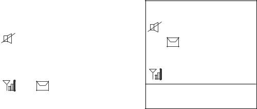
1.1.3Indications on the LCD
Below are all the indications which appear on the standby display on the transceiver unit.
INTL 1 |
SHIFT 2 |
Hi
Rx
6 |
14 |
|
8 |
116 |
4 |
|
|
|
|
5 |
|
|
|
|
7 |
|
|
|
|
|
|
DUP |
|
SCAN 3 |
AUTO ACK * |
9 |
10WATCH CH70 * |
LAT: 34°45' N |
11 |
10:45 UTC 12 |
LON: 135°45' E |
|
AUTO 13 |
|
Standby display on the transceiver unit |
||
|
|
|
|
Reference no. |
|
Meaning |
|
1 |
Displays the channel mode. |
||
(INTL / USA / WX / CANADA / INLND-WA / PRIV / (MEMO)) |
|||
|
|||
2 |
SHIFT is displayed if the shift function is active. Or channel mode (for |
||
example CANADA) is displayed at the MEMO mode. |
|||
|
|||
|
Displays the scan mode: SCAN, DUAL or no display. During the scan |
||
3 |
mode, channel indications are changed alternatively. No display means |
||
|
that the unit receives continuously on the same channel. |
||
4 |
Lights when the loudspeaker is off. Goes off when the loudspeaker is on. |
||
5 |
Displays the transmission output. |
||
(Hi=25W / Lo=1W) |
|
||
|
|
||
|
Displays reception signal strength by 4 steps. |
||
|
1. No signal. Only antenna mark is displayed. |
||
6 |
2. Less than 20 dB SINAD antenna mark and short bar |
||
|
3. 20 - 40 dB SINAD |
antenna mark and two bars |
|
|
4. 40 dB SINAD and more antenna mark and three bars |
||
7 |
RX is displayed during reception and TX is displayed when |
||
the RF signal detected at transmission state. |
|||
|
|||
8 |
Displays the current channel. |
||
PRIV channel: max three digits |
|||
|
|||
|
Is displayed when the DSC routine call is received. |
||
9 |
AUTO ACK: Automatic acknowledge |
||
|
MANUAL ACK: Manual acknowledge |
||
|
WATCH CH70 or WATCH VHF is selected at menu. |
||
10 |
If the CH70 board is defective, WATCH CH70 NG appears. |
||
|
If no MMSI is registered, the message “DSC NOT USABLE” appears. |
||
11 |
Displays the longitude and latitude of own ship. |
||
12 |
Displays UTC time. |
|
|
13 |
Displays AUTO for automatic data input (L/L, time data) from a navigation |
||
device or MANUAL for manual data input. |
|||
|
|||
14 |
Displays when un-read message(s) exist. |
||
*: “DISTRESS MODE” is displayed at distress calling.
1-5

1. OPERATIONAL OVERVIEW
Below are the indications which appear on the standby display on the remote handset.
|
INTL |
|
SHIFT |
|
|
|
|
|
|
|
||
|
|
|
|
|
03 |
|
|
|
|
|
WATCH CH70** |
|
|
Hi |
|
|
|
|
|
|
LAT: 12 34' N |
||||
|
|
|
|
|
|
|
LON: 123 45' E |
|||||
|
|
|
|
|
|
|
|
|
|
|||
|
Rx SCAN |
|
|
|
|
|
|
12:34 UTC |
||||
|
|
|
DUP |
|
|
|
|
|
AUTO |
|||
|
|
|
||||||||||
|
|
|||||||||||
|
|
|
|
|
|
|
|
|
||||
|
MANUAL ACK** |
3* |
|
|
|
|
|
|
||||
|
|
|
|
|
GPS ERROR |
|
|
|
|
|
|
|
|
|
|
|
|
|
|
|
|
||||
If you press |
at the left-hand screen, right-hand screen appears. |
|||||||||||
If you press |
at the right-hand screen, the left-hand screen appears |
|||||||||||
immediately.
The indications are the same as those on of the transceiver unit. The *- marked number is the terminal number of the remote station.
**: If no MMSI is registered, the message “DSC UNAVAIL” appears instead of MANUAL ACK and WATCH CH70. “DISTRESS MODE” is displayed at distress calling.
Note: The screen of the remote handset is smaller than the one of the transceiver unit. In this manual, display examples are from the transceiver unit. In the remote handset, scrolling with up or down arrow key displays same information as the screen of the transceiver unit.
Remote handset does not have a channel knob, but the transceiver unit does. To set private channel or memory channel at the remote station, use [2] key or [8] key.
1.1.4Audio alarms
When you receive a distress alert or other DSC call, the audible and visual alarms are released. For the distress or urgency call, the audio alarm sounds until the CANCEL key is pressed. For all other calls, the audible alarm sounds for two minutes and the automatically goes off. The tone of the alarm changes with the call received. By becoming accustomed to the tone, you can know which type of call you have received.
1-6
1. OPERATIONAL OVERVIEW
Alarm |
Frequency (interval) |
Safety call received |
1300 Hz and 0 Hz (250 ms) |
Routine, Ship’s Business call received |
880 Hz and 440 Hz (500 ms) |
While DISTRESS key is pressed for |
2200 Hz and 0 Hz (125 ms) |
three seconds |
|
Distress alert sent |
2200 Hz, continuous |
Own ship position not updated |
2200 Hz (50 ms), three beeps every two |
|
seconds |
Distress alert, urgency message |
1300 Hz and 2200 Hz (250 ms) |
received |
|
Message received from terrestrial |
750 Hz and 650 Hz (50 ms) 10 times |
telephone line |
Repeat OFF one second |
1.2VHF Basic Operation
1.2.1Turning the power on and adjusting contrast
To turn the power on, turn the VOLUME control clockwise until you hear a click. To adjust the contrast of the display, press the SHIFT key, and then rotate the CHANNEL knob or press the ▼ or ▲ key. To turn the power off, turn the control fully counterclockwise until you hear the click.
1.2.2Selecting channel modes, channels
Selecting channel modes
To change the channel mode, press the SHIFT key immediately followed by the 7 INT/USA key several times until desired mode is displayed. The following modes are available.
INTL |
: International mode |
USA |
: USA mode |
WX |
: Weather channel mode |
CANADA |
: CANADA mode |
INLND-WA |
: Rhine river mode (USED ON INLAND Waterways) |
PRIV |
: Private channel |
MEMO |
: Memory channel mode if registered |
Note: Private channels are available only where permitted by the authorities. The USA/WX, CANADA, INLND-WA , PRIV can also be set by a qualified serviceman.
Selecting channels
Rotate the CH selector clockwise (counterclockwise) to display desired channel. Use [2] key or [8] key at the remote station to set private channel or memory channel.
1-7
1. OPERATIONAL OVERVIEW
1.2.3Adjusting volume of loudspeaker
The VOLUME control adjusts the volume of the loudspeaker.
1.2.4Adjusting squelch
The SQUELCH control adjusts the squelch threshold level. Adjust it so that white noise heard in the loudspeaker just fades out. Perform this operation when no traffic is being received. AUTO squelch automatically reduces white noise. Usually select the AUTO position. Avoid turning the squelch too far clockwise — you may miss a long distance communication.
Note: To obtain correct scan watch/dual watch response, adjust the SQUELCH control precisely.
1.2.5Transmitting
Press the PTT (Push-to-talk) switch on the handset or microphone to talk, and release it to listen for the response. The VHF section keyboard accepts no key input when the PTT switch is operated.
Remarks on transmitting
•Before transmitting, think about the subjects which have to be communicated and, if necessary, prepare written notes to avoid unnecessary interruptions and ensure that no valuable time is wasted on a busy channel.
•Listen before commencing to transmit to make certain that the channel is not already in use.
1.2.6Selecting output power
After pressing the SHIFT key, each press of the 0 HI/LO key selects high or low output power. Also Hi or Lo appears on the screen depending on your selection.
The transmitter power is automatically set for low on the following channels:
International: |
CH15, CH17, CH75, CH76 |
USA: |
CH13, CH17, CH67, CH77; to operate USA channel 13 or 67 in |
|
high power, keep HI/LOW key pressed while talking into the |
|
handset. |
1.2.7Turning the loudspeaker on/off
To turn the loudspeaker on/off, press the SHIFT key, then the 1 key. See section 4.8 to set loudspeaker on or off according to handset onhook or offhook.
1-8

1. OPERATIONAL OVERVIEW
1.2.8Quick selection of CH16
Press the CH16 key to select CH16, the International Calling and Safety Channel. The use is limited to distress, safety and calling. The transmission on CH16 (156.800 MHz) should be limited to within 1 minute except for distress calling.
Avoid calling on CH16 for purposes other than distress, urgency and very brief safety communications when another calling channel is available.
1.2.9Dual watch
The dual watch function permits watch on CH16 and another selected channel. CH16 and another channel are watched at intervals of 0.15 seconds and one second, respectively.
To start dual watch, first select the other frequency to watch and then press the SHIFT key and 9 DW key in that order. When the receiver finds a signal on CH16, it locks on it and restarts dual watching after the signal on CH16 has gone. If another channel has traffic, it still continues dual watch. The speech is heard intermittently. If you are annoyed with the intermittence, turn off the dual watch by pressing the PTT switch on the handset or pressing the SHIFT and 9 DW key again.
1.2.10Scanning
The receiver scans all channels at intervals of 0.15 seconds in the selected channel mode in ascending channel order, watching CH16 between channels as below:
1  16
16  2
2  16
16  3
3  16
16  4...
4...
16 |
88 |
16 |
87 |
16 |
86 |
16... |
To start scanning, press the SHIFT and 8 SCAN in that order. When the receiver finds a signal, scanning is stopped on that channel and starts dual watch on it and CH16.
To turn off the scanning, press the PTT switch or press the SHIFT and 8 SCAN key.
1.2.11Remarks on voice communications
Automatic acknowledge (DSC operation) is automatically changed to manual acknowledge when voice communications begin. (The “auto” indication, however, remains on the screen.) This is done to prevent a break in communications. Automatic acknowledge is automatically restored once voice communications are terminated.
1-9
1. OPERATIONAL OVERVIEW
1.3DSC Operational Overview
Digital Selective Calling (DSC) is the global calling system adopted by the ITU-R and IMO for selective calling of coast station and ship radio stations. The DSC system is used for both safety and routine calling. The GMDSS requires the use of DSC for distress alerting and safety calls.
1.3.1LED warnings
The LED below the DISTRESS key lights continuously when the distress signal is transmitted.
The ALARM LED blinks in red (and alarm sounds) when a distress or urgent message is received. The LED can be extinguished and alarm silenced by pressing the CANCEL key.
The ALARM LED blinks in green (and alarm sounds) when a message other than distress or urgent is received. Alarm is automatically silenced two minutes after message is received.
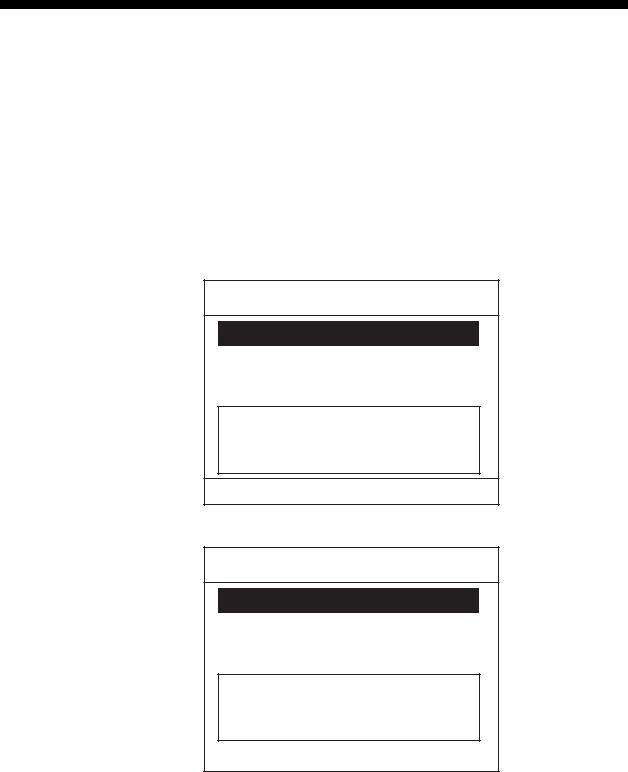
1.3.2DSC operational overview
Standby display
When the FM-8800D/S is turned on, the following display appears. This display is known as the “standby display.” This is where you will begin most operations.
INTL |
SHIFT |
|||
SCAN |
116 |
|||
Hi |
||||
|
||||
RX |
|
|||
|
|
|
SCAN |
|
|
|
|
||
|
|
|
||
|
|
|||
AUTO ACK |
WATCH CH70 |
|||
|
|
|||
LAT: 34 45' N |
10:17 UTC |
|||
LON: 135 45' E |
AUTO |
|||
Standby display (Transceiver unit)
INTL |
SHIFT |
Hi 116
RX SCAN
|
|
|
|
|
|
|
|
MANUAL ACK |
1 |
||
T VOL 5 SQ |
2 |
||
Standby display (Remote handset)
(Press the down arrow key of the remote handset to view rest of screen.)
If you get lost in operation you can return to the standby display by pressing the CANCEL key several times.
Note: In this manual, screen examples show the transceiver’s screens. To get the same information on the handset screen, press down or up arrow key.
1-10
1. OPERATIONAL OVERVIEW
Preparing and transmitting DSC messages
There are two methods by which you can prepare and transmit DSC messages, and they are shown below.
●Preparing message for immediate transmission 1. Press the CALL key at the standby display.
2. Select the call type.
3. Select other party (ID) if necessary.
4. Select the communications category.
5. Select the communications channel.
6. Press the CALL key more than three seconds.
●Transmitting a message stored in the memory
100 messages can be saved to the memory. You may open a memory-stored message and transmit it.
Distress alert transmission and output power
When the distress alert is transmitted (by pressing the DISTRESS key), the output power of the FM-8800D/S is automatically set to maximum (25 W).
When keyboard input is prohibited
DSC-related controls cannot be operated while a DSC message is being transmitted. (These controls are inoperative about 3 seconds during a DSC distress call; 0.5 seconds for other DSC calls.)
1.3.3Automatic acknowledge on/off
The automatic acknowledge feature of the DSC/watch receiver automatically transmits the acknowledge back (ACK BQ) signal to the sending station when an individual, position or polling call is received. (For position and polling calls, respective item on the AUTO ACK menu must be turned on to enable automatic acknowledge.) Automatic acknowledge can be turned on or off at the standby display by pressing the SHIFT and 5 keys in this order.
The message AUTO ACK or MANUAL ACK appears at the bottom of the standby display with each press of the keys.
Note 1: To give priority to own ship's communications while own ship is communicating, show MANUAL ACK by the above procedure.
Note 2: Automatic acknowledge is not possible under the following conditions: Priority: Distress, Urgency or Safety
Com Type: Fax, Data, No Info Com Freq: No Info
Off Hook
1-11

1. OPERATIONAL OVERVIEW
1.4Priority
If one or more remote stations are installed, the transceiver unit (main unit) has the highest priority. You can interrupt remote station operation at any time with the handset of the main unit. When you hook off the handset of the main unit, “OCCUPIED FM8800” (default. This may be change. See section 5.3) is indicated on all remote stations.
Each remote station has its own priority. The remote station ID (1-4) indicates its priority. The priority of the system is as follows.
DSC of main unit > Wing handset > Handset of main unit > 1 > 2 > 3 > 4
If you hook off No.4 remote station, for example, “Occupied Handset.4” is displayed on other remote stations. However, you can hook off and use No.1 handset.
How to set priority of the remote station
1.Disconnect the plug of a remote station to turn off the remote station.
2.While pressing the MENU key of a remote station, connect the plug to turn on the power.
Version No. 0550216-01.XX Now ID=01 Input
New ID (1-4)=
3.Press 1, 2, 3, or 4 key on the remote handset as appropriate followed by the ENT key. Never enter same number among different remote stations.
4.Turn off and on the power of the transceiver unit.
1-12
2. DSC DISTRESS COMMUNICATION
2.1Distress Alert Transmission from the DISTRESS Key
If a distress situation occurs, do as follows:
1.Open the DISTRESS key cover and press the DISTRESS key more than three seconds. The alarm sounds and the red lamp in the key blinks. The lamp will light steadily three seconds later and at the same time the distress alert is transmitted for three seconds.
The screen changes as follows.
1)When the DISTRESS key is pressed and held down,
**Compose Message **
CALL TYPE: DISTRESS
NATURE: UNDESIGNATED
POS : 12 ° 34’N 123° 45’E
AT : 12 : 34
Distress button
Pressed!
KEEP PRESSED FOR 3S
2)After the timer counts down to zero, “distress call in progress” is announced.
**Compose Message **
CALL TYPE: DISTRESS
NATURE: UNDESIGNATED
POS : 12 ° 34’N 123° 45’E
AT : 12 : 34
Distress Call
in Progress on CH70.
•When the distress is transmitted (called Distress Mode), you can communicate with the handset of the remote station.
•In the distress mode, the CALL, FILE and MENU keys are inoperative.
•To return to normal mode from the distress mode, turn the power off and on again.
2-1

2. DSC DISTRESS COMMUNICATION
3)The screen changes to “distress acknowledge (DIST ACK) waiting” display. In this condition, distress communication with CH16 may be possible.
**Compose Message **
CALL TYPE: DISTRESS
NATURE: UNDESIGNATED
POS : 12 ° 34’N 123° 45’E
AT : 12 : 34
Waiting for distress acknowledgement. CH16 Now available.
TIME TO GO : 4M 12S
4) When the DIST ACK is received,
Distress acknowledge received.
FROM : 003456789
ID IN DIST : 123456789
TCmd : DISTRESS ACK
NATURE : UNDESIGNATED
POS : 12 ° 34’N 123° 45’E
AT : 12 : 34 SIMP TP
CANCEL ALARM
Note: If you do not receive the distress alert acknowledge call, during 3.5 to 4.5 minutes the equipment automatically re-transmits the distress alert and then awaits the distress alert acknowledge call. This is repeated until the distress alert is acknowledged.
2.Press the CANCEL or ENT key. The screen changes as follows.
**Received Message **
APR08/’04 18:30 ECC : OK
DISTRESS ACK
FROM : 003456789
ID IN DIST : 123456789
TCmd : DISTRESS ACK
NATURE : UNDESIGNATED
POS : 12 ° 34’N 123 ° 45’E
AT : 12 : 34 SIMP TP
PRESS ENT
2-2

2. DSC DISTRESS COMMUNICATION
3.Press the ENT key. The standby display with CH16 and Hi appears.
4.Provide the following information to the coast station, using a handset on the transceiver unit or remote stations (if connected):
Distress communication
(1)Press the PTT switch and speak slowly and distinctly, “MAYDAY, MAYDAY, MAYDAY,” pronounced as the French expression “m’aider.”
(2)This is; "the name of your vessel and call sign" three times.
(3)“MAYDAY”
(4)This is; "the name of your vessel and call sign."
(5)Position in latitude and longitude;
(6)The nature of the distress;
(7)The kind of assistance desired;
(8)Number of persons on board;
(9)Any other information which might facilitate rescue, for example, length, color, and type of vessel.
(10)Indicate the end of message by saying “Over.”
Some countries do not have sea area "A1." In this case “ACK” from the coast station does not arrive over DSC. A ship nearby will contact the vessel in distress over CH16. After transmitting the distress alert, conduct voice distress communications as shown above.
2.2Distress Alert Transmission with Nature of Distress
If you want to transmit the distress alert with nature of distress specified, do as follows:
1.Open the DISTRESS key cover and press the DISTRESS key momentarily. The alarm sounds and the red lamp in the key blinks and after releasing the key within three seconds the alarm stops and the red lamp goes off. The following screen appears.
**Compose Message **
CALL TYPE : DISTRESS
NATUREUNDESIGNATED:
POS : 12Fire° 34N 123 ° 45E
AT : 12 :Flooding34
SIMP TPCollision
Grounding
T Listing
2-3

2. DSC DISTRESS COMMUNICATION
2.Rotate the channel knob to choose the nature of distress. On the remote handset, press the up or down arrow key.
|
SSinking |
UNDESIGNATED |
|
Fire |
Disabled & Adr |
Flooding |
Abandoning |
Collision |
Piracy |
Grounding |
Man over board |
TListing
3.Press the ENT key. The screen changes as follows.
** Compose Message **
CALL TYPE : DISTRESS
NATURE : Flooding
POS : 34 ° 41’ N 134 ° 30’ E
AT : 08 : 00
SIMP TP
The own ship's position and current time in UTC are displayed if your FM-8800D/S is connected to a navigation equipment, for example, GPS.
4.Press the DISTRESS key more than three seconds.
**Compose Message **
CALL TYPE: DISTRESS
NATURE: Flooding
POS : 12 ° 34’N 123° 45’E
AT : 12 : 34
Distress button
Pressed!
KEEP PRESSED FOR 3S
The distress alert with nature of distress, ship's position and time are transmitted. The sequence of display and procedures are the same as in paragraph 2.1.
2-4
Loading...