


 Loading...
MARINE RADAR FAR-2167DS/2167DS-BB/2167DS-D
Installation manual
SAFETY INSTRUCTIONS....................... |
i |
|
SYSTEM CONFIGURATION................. |
iii |
|
EQUIPMENT LISTS .............................. |
iv |
|
1. MOUNTING ..................................... |
1-1 |
|
1.1 Antenna Unit ........................................ |
1-1 |
|
1.2 |
Monitor Unit ........................................ |
1-7 |
1.3 |
Control Unit ........................................ |
1-10 |
1.4 |
Processor Unit .................................. |
1-15 |
1.5 |
Power Supply Unit ............................ |
1-16 |
2. WIRING ........................................... |
2-1 |
|
2.1 |
Wiring Overview................................... |
2-1 |
2.2 Antenna Unit ........................................ |
2-2 |
|
2.3 |
Monitor Unit (for FAR-2167DS)............ |
2-7 |
2.4 |
Processor Unit ..................................... |
2-8 |
2.5 |
Power Supply Unit ............................. |
2-13 |
2.6 |
Changing AC Power Specification ..... |
2-15 |
3. ADJUSTMENTS.............................. |
3-1 |
|
3.1 |
Initializing tuning .................................. |
3-1 |
3.2 |
Heading Alignment............................... |
3-2 |
3.3 Adjustment Sweep Timing.................... |
3-5 |
|
3.4 |
Suppressing Main Bang ....................... |
3-6 |
3.5 |
Other Settings ...................................... |
3-7 |
4. OPTIONAL EQUIPMENT ................ |
4-1 |
||
4.1 |
Gyro Converter GC-10 ......................... |
4-1 |
|
4.2 |
Memory Card Interface Unit ............... |
4-10 |
|
4.3 |
DVI-RGB Conversion Kit.................... |
4-13 |
|
4.4 |
BNC Connector Converter ................. |
4-16 |
|
5. IO DATA........................................... |
5-1 |
||
PACKING LISTS ................................ |
A-1 |
||
OTLINE DRAWINGS .......................... |
D-1 |
||
INTERCONNECTION DIAGRAM....... |
S-1 |
||
|
|
|
|
|
|
|
|
www.furuno.co.jp
All brand and product names are trademarks, registered trademarks or service marks of their respective holders.
The paper used in this manual is elemental chlorine free.
9-52 Ashihara-cho,
Nishinomiya, 662-8580, JAPAN
Telephone : +81-(0)798-65-2111
Fax |
: +81-(0)798-65-4200 |
All rights reserved. |
Printed in Japan |
Pub. No. IME-35230-E
(HIMA ) FAR-2167DS/BB
FURUNO Authorized Distributor/Dealer
A : FEB. 2007
E : FEB. 10, 2011
*00014869014*
*00014869014*
* 0 0 0 1 4 8 6 9 0 1 4 *
 SAFETY INSTRUCTIONS
The installer must read and follow all the safety instructions before attempting to install the equipment.
|
WARNING |
could result in death or serious injury. |
|
|
|
|
Indicates a potentially hazardous situation which, if not avoided, |
|
|
|
|
|
|
|
|
CAUTION |
may result in minor or moderate injury. |
|
|
|
|
Indicates a potentially hazardous situation which, if not avoided, |
|
|
|
|
|
|
|
|
Warning, Caution |
Prohibitive Action |
Mandatory Action |
|
|
|
|
|
|
 WARNING
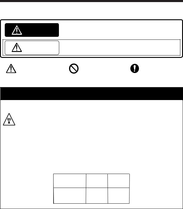
Radio Frequency Radiation Hazard
The radar antenna emits electromagnetic radio frequency (RF) energy which can be harmful, particularly to your eyes. Never look directly into the antenna aperture from a close distance while the radar is in operation or expose yourself to the transmitting antenna at a close distance.
Distances at which RF radiation levels of 100 W/m2 and 10 W/m2 exist are given in the table below.
Note: If the antenna unit is installed at a close distance in front of the wheel house, it may be necessary to halt transmission within a certain sector of antenna revolution. This can be done from the SCANNER menu.
Radiator type |
Distance to |
Distance to |
100 W/m2 |
10 W/m2 |
|
|
point |
point |
SN30AF |
0.60 m |
8.90 m |
SN36AF |
0.40 m |
7.40 m |
|
|
|
i
 WARNING
Do not open the equipment unless totally familiar with electrical circuits and service manual.
Only qualified personnel should work inside the equipment.
Wear a hard hat and safety belt when mounting the antenna unit.
Serious injury or death can result if someone falls from the radar antenna mast.
Construct a suitable service platform from which to install the antenna unit.
Serious injury or death can result if someone falls from the radar antenna mast.
Do not install units other than the antenna unit in a place subject to rain or water splash.
Fire, electrical shock or injury can result if water leaks into those units.
Turn off the power at the switchboard before beginning the installation.
Fire, electrical shock or injury can result if the power is on during the installation.
Use only the specified power cables.
Use of power cables that are thinner than those specified can cause fire.
Securely attach protective earth to the ship's body.
The protective earth is required to prevent electrical shock.
 CAUTION
A proper license is necessary to install a radar.
See your dealer for details.
Observe the following compass safe distances to prevent interference to a magnetic compass:
|
Standard |
Steering |
|
|
compass |
compass |
|
|
|
|
|
Antenna Unit |
4.30 m |
2.80 m |
|
(60 kw) |
|||
|
|
||
|
|
|
|
Monitor Unit |
1.55 m |
1.00 m |
|
(MU-201CR) |
|||
|
|
||
Processor Unit |
1.35 m |
0.85 m |
|
(RPU-013) |
|||
|
|
||
|
|
|
|
Control Unit |
0.30 m |
0.30 m |
|
(RCU-014) |
|||
|
|
||
Control Unit |
0.95 m |
0.60 m |
|
(RCU-015) |
|||
|
|
||
|
|
|
|
Control Unit |
0.65 m |
0.45 m |
|
(RCU-016) |
|||
|
|
||
|
|
|
|
Power Supply |
0.30 m |
0.30 m |
|
Unit (PSU-006) |
|||
|
|
||
Memory Card |
|
|
|
Interface Unit |
0.90 m |
0.60 m |
|
(CU-200) |
|
|
|
Switching Hub |
1.00 m |
0.60 m |
|
(HUB-100) |
|||
|
|
||
|
|
|
|
Monitor Unit |
1.65 m |
1.05 m |
|
(MU-190) |
|||
|
|
||
|
|
|
ii
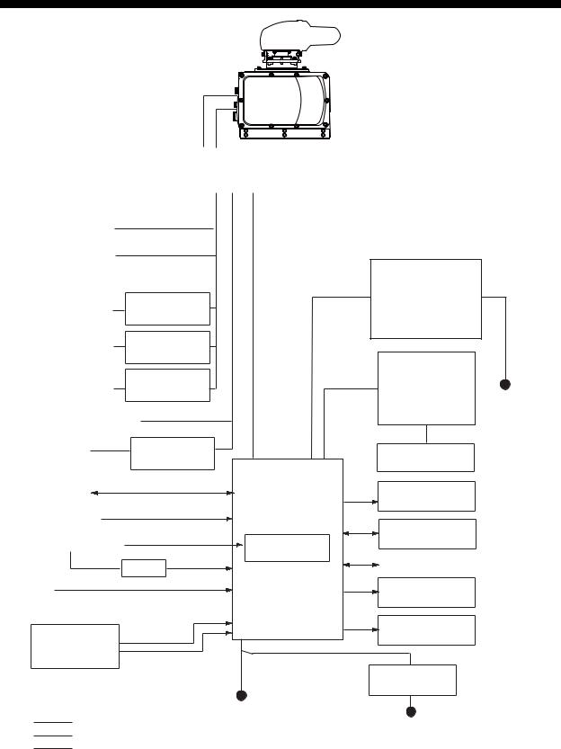
SYSTEM CONFIGURATION
RADIATOR SN30AF SN36AF
ANTENNA UNIT
CHASSIS
RSB-111/112
|
|
|
|
|
|
|
|
|
POWER SUPPLY UNIT |
|
|
||
|
|
PSU-006 |
|
|
|
|
|
|
|
|
|
||
200 VAC, 3φ, 50 Hz (For amtenna motor) |
|
|
|
|||
220 VAC, 3φ, 60 Hz |
|
|
|
|
|
|
380 VAC, 3φ, 50 Hz |
|
|
|
|
|
|
440 VAC, 3φ, 60 Hz |
|
|
|
|
|
|
110 VAC, 3φ, 60 Hz |
TRANSFORMER |
|
|
|
||
RU-5693 |
|
|
|
|||
|
|
|
|
|||
220 VAC, 3φ, 50 Hz |
TRANSFORMER |
|
|
|
||
RU-6522 |
|
|
|
|||
|
|
|
|
|||
440 VAC, 3φ, 50 Hz |
TRANSFORMER |
|
|
|
||
RU-5466-1 |
|
|
|
|||
|
|
|
|
|||
|
(For high voltage) |
|
|
|
||
100-115V/220-230 VAC |
|
|
|
|||
1φ, 50/60 Hz |
TRANSFORMER |
|
|
|
||
440 VAC, 1φ, |
|
|
|
|||
RU-1803 |
|
|
|
|||
50/60 Hz |
PROCESSOR |
|||||
|
|
|||||
|
|
|
||||
Navigator |
IEC-61162 Serial data |
|
UNIT |
|||
(I/O) |
RPU-013 |
|||||
|
||||||
Speed Log IEC-61162 Serial data |
|
|
|
|||
|
(Input) |
|
|
|
||
Gyrocompass |
GYRO CONVERTER |
|||||
|
|
|
|
GC-10 |
||
|
AD-100 |
|
|
|
||
AIS
Track Controller 
MEMORY CARD
INTERFACE UNIT
CU-200-FAR
MONITOR UNIT |
* |
|
MU-201CR |
|
|
(For FAR-2167DS) |
|
|
MU-190 |
|
|
(For FAR-2167DS-D) |
|
|
CONTROL UNIT |
|
|
RCU-014 |
|
|
(Standard) |
|
|
OR |
100-230 VAC |
|
RCU-015 |
||
1φ, 50/60 Hz |
||
(Trackball) |
||
|
||
CONTROL UNIT |
|
|
RCU-016 |
|
|
Radar Remote |
|
|
Display |
|
|
SWITCHING HUB |
|
|
HUB-100 |
|
|
Alarm |
|
|
VDR |
|
|
External |
|
|
Monitor |
|
|
TRANSFORMER |
|
|
RU-1803 |
|
100-115 VAC/
: Standard supply |
220-230 VAC |
|
: Optional supply |
||
1φ, 50/60 Hz |
||
: Local supply |
||
|
* FAR-2167DS-BB is not equipped with a monitor unit. Procure one locally.
440 VAC
1φ, 50/60 Hz
Equipment category
Unit |
Category |
|
|
Antenna |
Exposed to weather |
|
|
Other units |
Protected from weather |
|
|
iii

EQUIPMENT LISTS
Standard supply
Name |
Type |
Code No. |
Qty |
Remarks |
|
|
|
|
|
|
|
Antenna Unit |
SN30AF |
– |
1 |
Radiator |
|
|
|
|
|
|
|
|
SN36AF |
– |
|
|
|
|
|
|
|
||
|
|
|
|
|
|
|
RSB-111 |
– |
|
200 VAC, 3φ, 50 Hz |
Chassis |
|
|
|
1 |
220 VAC, 3φ, 60 Hz |
|
|
|
|
|
|
|
|
RSB-112 |
– |
380 VAC, 3φ, 50 Hz |
|
|
|
|
|
|||
|
|
|
|
440 VAC, 3φ 60 Hz |
|
|
|
|
|
|
|
Power Supply |
PSU-006 |
– |
1 |
|
|
Unit |
|
|
|
|
|
|
|
|
|
|
|
Monitor Unit |
MU-201CR |
– |
1 |
For FAR-2167DS |
|
|
|
|
|
|
|
|
MU-190 |
– |
|
For FAR-2167DS-D |
|
|
|
|
|
|
|
Processor Unit |
RPU-013 |
– |
1 |
|
|
|
|
|
|
|
|
Control Unit |
RCU-014 |
– |
1 |
Standard-type |
|
|
|
|
|
|
|
|
RCU-015 |
– |
Trackball-type |
|
|
|
|
|
|||
|
|
|
|
|
|
Installation |
CP03-31501 |
008-573-780 |
1 |
For antenna unit |
|
Materials* |
|
|
|
|
|
CP03-25700 |
000-080-435 |
|
15 m signal cable (RW-9600) |
||
|
|
||||
|
|
|
|
|
|
|
CP03-25710 |
000-080-436 |
1 |
30 m signal cable (RW-9600) |
|
|
|
|
|
|
|
|
CP03-25730 |
000-082-191 |
40 m signal cable (RW-9600) |
||
|
|
||||
|
|
|
|
|
|
|
CP03-25720 |
000-080-437 |
|
50 m signal cable (RW-9600) |
|
|
|
|
|
|
|
|
CP03-25800 |
000-080-434 |
1 |
Cable assy. for monitor unit |
|
|
|
|
|
|
|
|
CP03-25602 |
008-535-940 |
1 |
For processor unit |
|
|
|
|
|
|
|
|
CP03-31401 |
008-572-750 |
1 |
For power supply unit |
|
|
|
|
|
|
|
|
CP03-25604 |
008-539-850 |
1 |
For control unit |
|
|
|
|
|
|
|
Accessories* |
FP03-09810 |
008-536-010 |
1 |
For monitor unit. |
|
|
|
|
|
|
|
|
FP03-09850 |
008-535-610 |
1 |
For standard-type control unit |
|
|
|
|
|
|
|
|
FP03-09860 |
008-535-690 |
For trackball-type control unit |
||
|
|
||||
|
|
|
|
|
|
|
FP03-10101 |
008-538-730 |
1 |
For antenna unit |
|
|
|
|
|
|
|
Spare Parts* |
SP03-14404 |
008-535-910 |
1 |
For processor unit, 100 VAC |
|
|
|
|
|
|
|
|
SP03-14405 |
008-535-920 |
For processor unit, 220 VAC |
||
|
|
||||
|
|
|
|
|
|
|
SP03-14401 |
008-535-990 |
1 |
For monitor unit |
|
|
|
|
|
|
|
|
SP03-15501 |
008-572-730 |
1 |
For power supply unit, 100 VAC |
|
|
|
|
|
|
|
|
SP03-15502 |
008-572-740 |
For power supply unit, 220 VAC |
||
|
|
||||
|
|
|
|
|
|
* See packing list at end of this manual.
iv
Optional equipment
Name |
Type |
Code No. |
Remarks |
|
Gyro Converter |
GC-10-2 |
000-080-440 |
See Chapter 4. |
|
|
|
|
|
|
Stepdown |
RU-1803 |
– |
440 to 100 VAC, for processor unit |
|
Transformer |
|
|
|
|
RU-5693 |
– |
110 to 220 VAC, 3φ, for antenna unit |
||
Unit |
||||
|
|
|
||
RU-6522 |
– |
220 to 200 VAC, 3φ, for antenna unit |
||
|
||||
|
|
|
|
|
|
RU-5466-1 |
– |
440 to 200 VAC, 3φ, for antenna unit |
|
Memory Card |
CU-200-FAR |
000-081-568 |
w/CP03-27430, see Chapter 4. |
|
Interface Unit |
|
|
|
|
|
|
|
|
|
External Alarm |
OP03-21 |
000-030-097 |
|
|
Buzzer |
|
|
|
|
|
|
|
|
|
Control Unit |
RCU-016 |
000-080-299 |
Remote type, w/FP03-09860 |
|
|
|
|
|
|
RAM Card |
O0RAM08MC-005 |
004-376-740 |
8MB |
|
|
|
|
|
|
DVI-RGB |
OP03-180-1 |
008-545-590 |
For installation in field. |
|
Converter Kit |
|
|
|
|
OP03-180-2 |
008-536-070 |
For installation in field. See Ch. 4. |
||
|
|
|
|
|
Cable Assy. |
XH10P-W-6P L=20M |
000-149-748 |
Processor unitQControl unit, 20 m |
|
|
|
|
|
|
|
XH10P-W-6P L=30M |
000-149-749 |
Processor unitQControl unit, 30 m |
|
|
|
|
|
|
|
XH10P-W-5P-A L=10M |
000-149-050 |
Between control units, 10 m |
|
|
|
|
|
|
|
XH10P-W-5P-A L=20M |
000-149-051 |
Between control units, 20 m |
|
|
|
|
|
|
|
XH10P-W-5P-A L=30M |
000-149-052 |
Between control units, 30 m |
|
|
|
|
|
|
|
DVI-D/D S-LINK 10M |
000-150-200 |
Processor unitQControl unit, 10 m |
|
|
|
|
|
|
|
S03-9-5(8-8P) |
008-206-640 |
External radar, 5 m, 8-8P |
|
|
|
|
|
|
|
S03-9-10(8-8P) |
008-206-650 |
External radar, 10 m, 8-8P |
|
|
|
|
|
|
|
S03-9-15(8-8P) |
008-209-160 |
External radar, 15 m, 8-8P |
|
|
|
|
|
|
Installation |
CP03-28900 |
000-082-658 |
FR-FTPC-CY 10 m, modular |
|
Materials |
|
|
connector MPS588-C, 2 pcs. |
|
(Armored LAN- |
|
|
|
|
CP03-28910 |
000-082-659 |
FR-FTPC-CY 20 m, modular |
||
Cable Kit) |
|
|
connector MPS588-C, 2 pcs. |
|
|
|
|
|
|
|
CP03-28920 |
000-082-660 |
FR-FTPC-CY 30 m, modular |
|
|
|
|
connector MPS588-C, 2 pcs. |
|
|
|
|
|
|
Bracket Assy. |
FP03-09820 |
008-535-560 |
Hanger assy. for monitor unit |
|
|
|
|
|
|
Handgrip Assy. |
FP03-09840 |
008-535-570 |
For monitor unit |
|
|
|
|
|
|
Dust Cover |
03-163-1201 |
100-307-260 |
For monitor unit |
|
|
|
|
|
|
Clamp Assy. |
OP03-182 |
008-535-620 |
For RCU-014 |
|
|
|
|
|
|
Flush Mount Kit |
FP03-09870 |
008-535-630 |
For control unit |
|
|
|
|
|
|
|
OP03-198 |
001-008-050 |
|
|
|
|
|
|
|
Connection |
OP03-183 |
008-535-640 |
RCU-014QMU-201CR |
|
Stand |
|
|
|
|
OP03-185 |
008-535-660 |
RCU-014 |
||
|
|
|
|
|
Hanger Kit |
FP03-10201 |
008-539-530 |
Desktop inst. kit for CU-200-FAR |
|
|
|
|
|
|
BNC |
DSUB-BNC-1 |
000-148-528 |
For connecting VDR |
|
Connector |
|
|
|
|
Converter |
|
|
|
|
|
|
|
|
|
Switching Hub |
HUB-100 |
– |
See Operator's Manual for HUB-100, |
|
|
|
|
issued separately. |
|
|
|
|
|
|
Hood |
FP03-11500 |
001-020-090 |
For MU-201CR display unit |
|
|
|
|
|
|
Slim Hood |
FP03-11510 |
001-034-390 |
For MU-201CR display unit |
v
This page is intentionally left blank.
vi

1. MOUNTING
NOTICE
Do not apply paint, anti-corrosive sealant or contact spray to coating or plastic parts of the equipment.
Those items contain organic solvents that can damage coating and plastic parts, especially plastic connectors.
1.1 Antenna Unit
Mounting considerations
The antenna unit is generally installed either on top of the wheelhouse, on the radar mast, or on a suitable platform. The mounting location should afford a good all-round view and satisfy the siting and mounting considerations mentioned below.
Siting
•No funnel, mast or derrick should be within the vertical beamwidth of the antenna unit in the bow direction, especially zero degrees ±5°, to prevent blind sectors and false echoes on the radar picture.
•Deposits and fumes from a funnel or other exhaust vent can adversely affect the aerial performance and hot gases may deform the radiator. The antenna unit must not be mounted where the temperature is more than 70°C.
•Locate a direction finder antenna clear of the antenna unit to prevent interference to the direction finder. A separation of more than two meters is recommended.
•Choose a location where reflections from the radar reflector will not be received by the radar antenna.
•The "standard" antenna unit orientation has the cable glands directed toward the bow.
•Leave sufficient space around the unit for maintenance and servicing. See the antenna unit outline drawing for recommended maintenance space.
Mounting
•Use rope and crane to hoist the antenna unit to the mounting location. Lifting fixtures are provided on the antenna chassis to which to fasten rope.
•Mount the unit parallel to the waterline.
•A hole is required in the mounting platform for the antenna cable.
•An appropriate platform should be constructed at the mounting location to facilitate installation and maintenance work.
•Connect ground wire between antenna terminal on antenna chassis and ground point.
•If the mounting platform is made of steel paint it to prevent electrolytic corrosion. DO NOT paint the antenna radiator.
1-1
Installation precaution for S-band antenna unit
If an S-band antenna unit is mounted near the end of a platform to provide sufficient rotation clearance for the radiator, the antenna unit, because of its weight, will swing up and down by ship's vibration and rolling. This exerts excessive levels of stress at the base of the radiator, which can damage the radiator. To prevent this, relocate the antenna unit, or if relocation is not possible reinforce the platform.
Mast for
DF, etc.
Remarkable vibration (pitching)
Mounting position
EXAMPLE
Mast for DF
Mount antenna unit directly on mast or on a platform, as near as
possible to center of mast.
Mounting precaution for S-band antenna unit
1-2
Assembling the antenna unit
The antenna unit should be assembled before mounting it. Follow the procedure below to assemble the antenna unit.
1.Screw the guide pins (2 pcs.) in the radiator.
2.Remove the protective cap from the choke guide and radiator.
3.Grease the O-ring and set it to the groove on the choke guide.
4.Place the radiator on the radiator bracket. (Radiator direction is shown by the logo on the bracket. If reversely oriented the radiator cannot be set to the bracket.)
5.Loosely fix the radiator to the radiator bracket with hex bolts (M10×25), spring washers and flat washers.
6.Remove the guide pins and tighten the hex bolts.
Spring washer, flat washer, 10 pcs. each, M10x25
Protective cap Radiator bracket
Choke guide O-ring
Antenna radiator
Do not remove teflon tube from the center conductor.
Radiator front
Guide pin (2 pcs.)
Arrow mark for the radiator front.
 CAUTION
Be sure to remove the guide pins after fixing the radiator.
Injury may result if the guide pins loosen and fall from antenna radar platform.
Assembling the antenna unit
1-3
How to hoist the antenna unit
1.Fix the antenna radiator to the antenna unit chassis as shown on page 1-3.
2.Attach the lifting fixtures and collars as shown below.
3.Position the radiator as shown below and arrange the ropes A and B.
Lifting fixture |
Supplied as accessories. |
|
|
|
|
Collar |
|
Remove after installation. |
|
|
|
Spring washer |
||
|
Spring washer |
|
Flat washer (M12) |
|
Hex bolt (M12x20) |
|
(Torque: 63.5 Nm) |
|
|
|
|
Remove lifting fixture, coat threads of hex bolts with silicone grease, and
then insert bolts in antenna chassis.
Lifting hook (2 pcs.)
|
* |
B 1.8m |
A 2m |
|
|
|
|
*
* 2. Place protective material (cardboard, foam, etc.) between rope and radiator at the asterisk-marked locations, to prevent damage to radiator.
Attachment of lifting fixtures, collar and ropes
1-4
Fastening the antenna unit to the mounting platform
 WARNING
Do not open the equipment unless totally familiar with electrical circuits and service manual.
Only qualified personnel should work inside the equipment.
Wear a hard hat and safety belt when mounting the antenna unit.
Serious injury or death can result if someone falls from the radar antenna mast.
Construct a suitable service platform from which to install the antenna unit.
Serious injury or death can result if someone falls from the radar antenna mast.
Note: The antenna is made of cast aluminum, which is subject to electrolytic corrosion if the mounting platform is steel or iron. To prevent electrolytic corrosion, use the supplied seal washers and corrosion-proof rubber mat.
Fix the antenna unit to the mounting location, referring to the procedure below and the illustration on the next page.
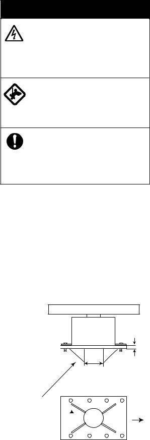
1.Referring to the antenna outline drawing, prepare a mounting platform. Drill eight fixing holes of 15 mm in diameter in the mounting platform or the deck.
•The diameter of the mast for the mounting platform must be over 250 mm.
•The thickness of the platform must be over 15 mm.
•The reinforcement rib must be installed diagonally as shown below.
Over 15 mm
Use two nuts. 
At least 250 mm in diameter, Thickness at least 6 mm.
Install the reinforcement rib diagonally. 
Ship's bow
Bottom view
Installation of reinforcement ribs
1-5
2.Lay the corrosion-proof rubber mat (supplied) on the mounting platform, aligning the holes on the rubber mat with the fixing holes on the mounting platform.
3.Lay the antenna unit on the rubber mat, orienting it so the cable gland is directed toward ship's bow. Remove the lifting fixtures and collars.
4.Fix the antenna base to the mounting platform with four M12×70 hex bolts, nuts, washers and seal washers (supplied).
5.Arrange the ground point at a location on the mounting platform that is within 300 mm from the ground terminal on the antenna unit. Fasten the ground wire (RW-4747, 340 mm) there, using the M6×25 hex bolt, nut and washers.
6.Connect the other end of the ground wire to the ground terminal on the antenna unit.
7.Coat the ground terminal, ground point on the mounting platform and fixing bolts on the antenna unit with anticorrosive sealant (supplied).
Ground terminal
|
Hex bolt |
||||||
|
|
|
|
|
Flat washer |
||
Ground wire |
|
|
|
|
Flat washer |
||
|
|
|
|
Spring washer |
|||
|
|
|
|
|
|||
|
|
|
|
Hex nut |
|||
Coat with |
OR |
||||||
anticorrosive |
|||||||
|
|
|
|
|
|
||
sealant. |
|
|
|
|
|
|
|
Ground wire |
|
Hex nut |
|||||
|
|
||||||
|
|
|
Spring washer |
||||
|
|
||||||
|
|
|
|
|
Flat washer |
||
|
|
|
Hex bolt |
||||
|
|
|
|
|
|
|
|
|
|
|
|
|
|
|
|
|
|
|
|
|
|
|
|
Welding
Arrange ground terminal as close as possible to antenna unit.
Seal washer
Corrosionproof rubber mat
Use two nuts. (Torque: 63.5 Nm)
Lay corrosion-proof rubber mat, bolt antenna unit to mounting location, and coat exposed hardware with anticorrosive sealant.
Fasten ground wire and then coat with anitcorrosive sealant.
Ground wire
Antenna chassis
Ground terminal provided on antenna base.
Mounting the antenna unit
1-6
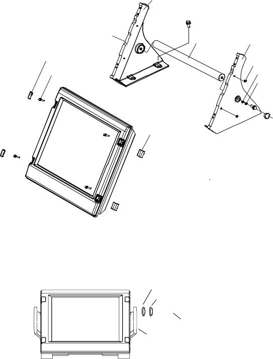
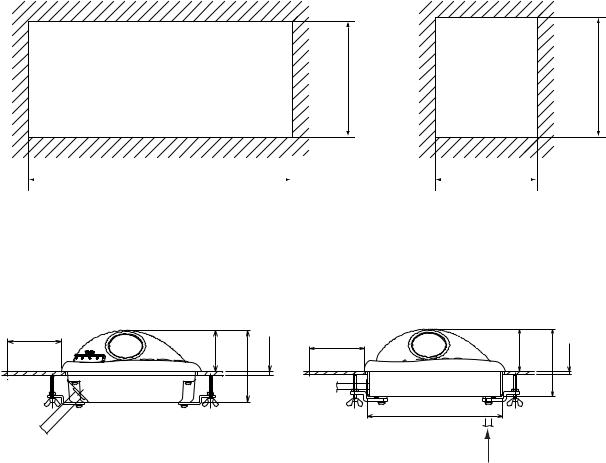
1.2 Monitor Unit
The monitor unit is can flush mounted in a panel or mounted on a desktop (requires optional accessories).
The FAR-2167DS-BB is not equipped with a monitor unit. Procure a suitable monitor unit locally. Recommended monitor: SXGA (1280×1024), aspect ratio 5:4.
For MU-190, see the applicable Operator’s Manual.
Mounting considerations
When selecting a mounting location, keep in mind the following points:
•Select a location where the screen can be viewed conveniently while facing the bow.
•Locate the unit out of direct sunlight and away from heat sources because of heat that can build up inside the cabinet.
•Locate the unit away from places subject to water splash and rain.
•Leave sufficient space on the sides and rear of the unit to facilitate maintenance, referring to the outline drawing for maintenance space.
•The monitor unit will give interference to a magnetic compass if it is placed too close to the compass. Observe the compass safe distances on page ii to prevent interference to the compass.
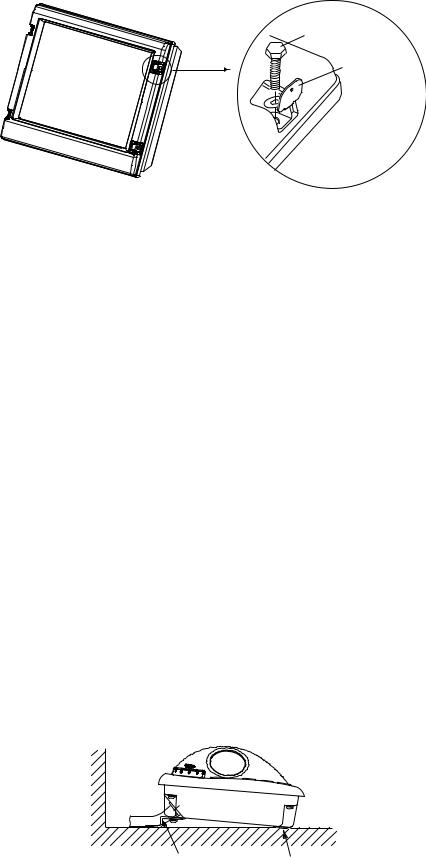
Mounting procedure
Flush mounting
Follow the procedure below to mount the monitor unit in a console.
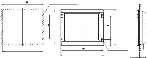
1.Make a cutout in the mounting location referring to the outline drawing shown below.
2.Set the monitor unit to the hole and fix it with four self-tapping screws (6×30).
3.Attach panel hooks near the fixing holes (upper part). See next page. These are used to pull out the monitor unit from the panel for servicing.
4.Attach four panel covers to the fixing holes.
506 |
1 |
4-FIXING HOLES |
|
|
|
|
|
|
|
|
|
|
|
|
1 |
420 |
|
1 |
454 |
|
|
296 |
|
296 |
|
||
|
|
|
|
(79) |
|
|
490 |
|
506 |
1 |
4-φ8 |
|
|
|
|
534 |
|
FIXING HOLES |
80 |
|
|
|
|
|
|
30 |
|
Mounting dimensions for flush mounting the monitor unit
1-7
Panel hook
Panel cover
Fixing screw
How to attach panel hook and panel cover
Note: If you need to remove the monitor unit from the console, remove the four panel covers with your fingernail and use two panel hooks supplied as accessories to lift the monitor unit.
Desktop mounting
Use the optional desktop mouting kit (Type: FP03-09820, Code No.: 008-535-560) to mount the monitor unit on a desktop.
Contents of desktop mounting kit FP03-09820
Name |
Type |
Code No. |
Qty |
|
|
|
|
Hanger L |
03-163-1111 |
100-305-141 |
1 |
|
|
|
|
Hanger R |
03-163-1112 |
100-305-181 |
1 |
|
|
|
|
Hanger stay |
03-163-1113 |
100-305-191 |
1 |
|
|
|
|
Hole plug |
CP-30-HP-13 |
000-160-074-10 |
2 |
|
|
|
|
Snap button |
KB-13, Black |
000-570-276-10 |
4 |
|
|
|
|
Hex. bolt |
M6×25 |
000-162-884-10 |
4 |
|
|
|
|
Hex. bolt |
M10×30 |
000-162-884-10 |
2 |
|
|
|
|
Spring washer |
M10 |
000-864-261 |
2 |
|
|
|
|
Flat washer |
M10 |
000-864-131 |
2 |
|
|
|
|
1.Assemble two hangers and hanger stay with two hex bolts (M10×30), flat washers and spring washers and cover each hex bolt with hole plug.
2.Fix the above assembly to the mounting location with four hex bolts (M12, dockyard supply).
3.Fasten the monitor unit to the mounting hanger assembly with four hex bolts (M6×25, supplied).
4.Cover each hex bolt with a panel cover (4 pcs.).
5.Cover fixing holes for hand grips with snap buttons (4 pcs).
1-8
Panel cover
Hex bolt (M6x25)
Attaching hand grips
Hanger (L)
M12 bolts for fixing (Dockyard supply)
Hanger stay |
Hanger (R) |
Snap button
Flat Washer M10
Spring Washer M10
Hex bolt
 M10x30
Hole plug
Panel cover
 To remove this, insert fingernail in groove.
Fastening monitor unit to hanger
Hand grips are optionally available for the desktop-mount monitor unit. Attach them as follows:
1.Remove the snap buttons attached at step 5 on the previous page.
2.Fix hand grips with wave washers, rosette washers and flat head screws.
Wave washer
Rosette washer
Flat head screw (torque: 7.6 Nm)
Hand grip
How to attach hand grips
Attaching hood
When it is too bright in the daytime, use the optional hood (Type: FP03-11500, Code No.: 001-
020-090) to shade the screen.
Contents of hood
Name |
Type |
Code No. |
Qty. |
|
|
|
|
Hood |
FP03-11501 |
001-020-120 |
1 |
|
|
|
|
Fixing plate |
03-163-2202-0 |
100-335-560-10 |
4 |
|
|
|
|
Screw |
M4x10 D=13 US304 |
000-862-543 |
4 |
|
|
|
|
1-9
1.Desktop mounting: Fasten the fixing plates to the fixing holes with the hex head bolts (supplied).
Flush mounting: Fasten the display unit to the mounting location, and then attach the fixing plates with four self-tapping screws.
Hex head bolt
 Fixing plate

 Fixing hole
2.Attach the hood to the display unit (the hood is outside of the fixing plates).
3.Fasten the hood to the fixing plates with four screws supplied (M4x10).
1.3 Control Unit
Mounting considerations
The control unit may be mounted on a desktop, with or without the KB fixing metal (supplied) which mounts the control unit at an angle. When selecting a mounting location, keep in mind the following points:
•Select a location where the control unit can be operated conveniently while observing the display screen.
•Locate the unit away from heat sources because of heat that can build up inside the cabinet.
•Locate the equipment away from places subject to water splash and rain.
•Determine the mounting location considering the length of the signal cable between the control unit and the processor unit. (A 10 m signal cable is attached to the control unit.)
•A magnetic compass will be affected if the control unit is placed too close to it. Observe the compass safe distances on page ii to prevent interference to a magnetic compass.
Mounting procedure
Fixing with KB (keyboard) fixing plate
The KB fixing plate sits the control unit at a comfortable angle, like the retractable legs on a PC keyboard.
1.Fix the KB fixing plate to the bottom of the control unit.
2.Attach cushions (three for RCU-014, two for RCU-015/RCU-016) to the bottom of the control unit as shown below.
3.Fix the unit to a desired location with self-tapping screws (local supply).
KB fixing plate |
Cushion |
Control unit RCU-014/015/016, side view
1-10
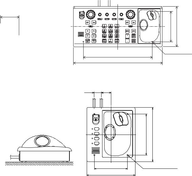
Fixing without KB fixing plate
1.Drill four mounting holes of 5 mm diameter, referring to the outline drawing at the back of this manual.
2.Fix the control unit with four screws (M4) from the under side of the desktop. (M4 screws with a sufficient length for the thickness of the desktop should be provided locally.)
#70
136±1 |
180 |
# Minimum recommended service space |
308±1 |
4-M4 (Fixing holes |
|
(bottom) |
|
|
398 |
|
Mounting dimensions for control unit RCU-014
24 32
F1
F2
F3
F4
136±1 |
180 |
110±1 |
4-M4 (Fixing holes) |
160 |
(REAR) |
|
Mounting dimensions for control unit RCU-015/RCU-016
1-11
Flush mounting
Use the optional flush mount kit FP03-09870 (Code No. 008-535-630) to flush mount the control unit RCU-014, RCU-015 and/or RCU016 in a console.
Contents of flush mount kit for RCU-014/015/016
Name |
Type |
Qty |
|
|
|
Mounting plate |
03-163-7531 |
4 |
|
|
|
Hex bolt |
M5 |
4 |
|
|
|
Wing screw |
M5×40 |
4 |
|
|
|
Pan head screw |
M4×12 |
4 |
|
|
|
1. Prepare a cutout in the mounting location as shown in the figure below.
170±2 |
176±2 |
388 ±2 |
|
150±2 |
|
|
|
|
|
Flush mount cutout for RCU-014 Flush mount cutout for RCU-015 and RCU-016
2.Set the control unit to the cutout.
3.From the rear side, attach the mounting plate to the control unit with four screws.
4.Screw the wing screw to each mounting plate and then insert hex bolt to each wing screw.
5.Fasten each wing screw and then fasten the hex nuts as shown in the figure below.
#70 |
92 (P) |
#70 |
|
53 |
|||
|
|||
|
|
171 |
|
|
Note: P |
< |
|
|
=10 |
53 |
86 (P) |
# Minimum recommended service space
To change location of cable entrance, see page 1-14.
Flush mountmounting dimensions for control unitRCU-014 (left)and RCU-015/RCU-016
1-12
Connecting RCU-016 in series with RCU-014
1. Pass the cable from RCU-016.
2. Plug in connector to J502.
3. Clamp the copper part of the cable with the cable clamp.
Control unit RCU-014, inside view
1-13

Changing the cable entrance on control unit RCU-015/RCU-016
To change the cable entrance from the side (default) to the bottom, modify the unit as shown below.
Screw M3X8
(torque: 10.78 Nm)
3. Pass cable thru this hole.
4. In here, clamp copper part of cable with cable clamp removed at step 1.
Bottom of unit
2. Pull out cable.
Cable clamp 03-163-7804
Screw M4X8
(torque: 1.47 Nm)
1.Remove cable clamp.
J522: Plug in here to connect RCU-016 in series with RCU-015.
Changing cable entrance on control unit RCU-015/RCU-016
1-14
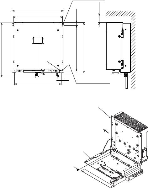
1.4 Processor Unit
Mounting considerations
When selecting a mounting location, keep in mind the following points:
•Locate the processor unit away from heat sources because of heat that can build up inside the cabinet.
•Locate the unit away from places subject to water splash and rain.
•Leave sufficient space at the sides and rear of the unit to facilitate maintenance, referring to the outline drawing.
•A magnetic compass will be affected if the processor unit is placed too close to it. Observe the compass safe distances on page ii to prevent interference to a magnetic compass.
Mounting procedure
Fix the unit with four M6 bolts or self-tapping screws.
|
2-φ7 FIXING HOLES |
385 |
#50 |
|
|
370±1 |
25 |
410 |
340±1 |
380 |
|
R3 |
|
|
|
. |
|
|
|
|
5 |
|
350±1 |
|
7 |
2-FIXING NOTCH |
|
|
||
#Minimum recommended service space
Mounting dimensions for processor unit
Upper case assy.
Note: If you fix the unit with the cable entry up, do not unfasten the screw (M3x10) that fastens the upper case assy. and lower case assy. of the processor unit.
Lower case assy.
Do not unfasten this screw.
1-15
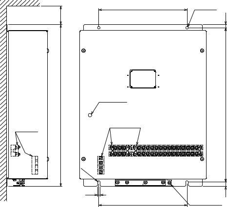
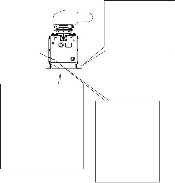
1.5 Power Supply Unit
Mounting considerations
The power supply unit may be mounted on a bulkhead or a deck. Because it has no operation requirements it can be located almost anywhere, provided the location is well ventilated.
Mounting procedure
Fix the unit to the mounting location with four 6×20 self-tapping screws (local supply). For mounting on a bulkhead, do the following:
1.Mark location for mounting holes.
2.Screw in the self-tapping screws at the location for the bottom fixing holes, leaving a gap of about 5 mm between the bottom of the screw head and bulkhead.
3.Set the unit to the screws inserted at step 1.
4.Fasten the self-tapping screws at the top of the unit.
5.Tighten all self-tapping screws.
#50
240±1 2-φ7
FIXING
HOLE
9
440
TERMINAL
WINDOW
LED
TERMINAL
420±1
R3 . 5
7
240±1
#: MAINTENANCE SPACE
Mounting dimensions for power supply unit
GND TERMINAL
(11)
1-16
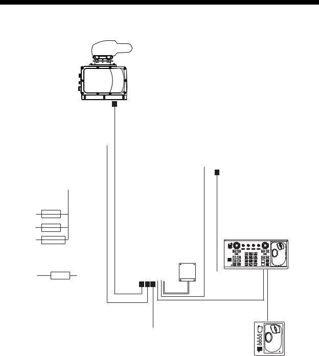
2. WIRING
2.1 Wiring Overview
ANTENNA UNIT
POWER SUPPLY UNIT
|
|
|
|
|
|
|
|
|
|
|
|
|
|
|
|
|
|
|
TPYCY-1.5 |
TPYCY-2.5 |
|
|
|
|
|
|
|
|
||||
|
|
|
|
|
|
|
|
|||
|
|
|
|
|
|
|
|
|
|
|
|
|
|
|
|
|
|
|
|
|
|
|
|
|
|
|
|
|
|
|
|
|
|
|
|
|
|
|
|
|
|
|
|
|
|
|
|
|
|
|
|
|
|
|
|
|
|
|
|
|
|
|
|
|
|
|
|
|
|
|
|
|
|
|
|
|
|
|
|
|
|
|
|
|
|
|
|
TB801
TB802
MONITOR UNIT
200 VAC, 3φ, 50 Hz |
|
|||||
220 VAC, 3φ, 60 Hz |
|
2.5- |
||||
|
||||||
380 VAC, 3φ, 50 Hz |
||||||
440 VAC, 3φ, 60 Hz |
|
TPYC |
||||
|
||||||
110 VAC, 3φ, |
|
|
|
|
|
|
|
|
|
|
|||
RU-5693 |
|
|
|
|||
60 Hz |
|
|
|
|
|
|
|
|
|
|
|
|
|
220 VAC, 3φ, |
|
|
|
|
|
|
RU-6522 |
|
|
|
|
||
50 Hz |
|
|
|
|
|
|
|
|
|
|
|
|
|
440 VAC, 3φ, |
RU-5466-1 |
|
|
|||
50 Hz |
|
|
|
|
|
|
|
|
|
|
|
|
|
100-115 VAC/220-230V, |
|
|
||||
|
|
|||||
1φ, 50/60 Hz |
|
|
|
|
|
|
440 VAC, |
RU-1803 |
|
||||
|
||||||
1φ, 50/60 Hz
 : Fabrication required
DPYC-2.5
TPYC-1.5
RW-9600 |
5/10m |
CONTROL UNIT |
|
PROCESSOR UNIT |
SINGLELINKD/D- |
||
15/30/40/50 m |
|
|
|
(Max.100 m) |
|
|
|
|
|
DPYC-2.5 |
|
|
DVI |
(RCU-014 or RCU-015) |
|
|
|
||
MEMORY CARD |
|
|
|
INTERFACE |
|
|
|
CU-200-FAR |
|
|
|
|
|
100-230 VAC |
XH10P-W-5P |
|
|
L=10/20/30 m |
|
|
|
1φ, 50/60 Hz |
|
|
|
|
|
XH10P-W-6P L=1.5/10/20/30m |
CONTROL UNIT |
||
DPYC-2.5 |
|
|
|
|
|
|
(RCU-016) |
100-115V/220-230 VAC |
|
|
F1 |
1φ, 50/60Hz |
|
|
F2 |
|
|
F3 |
|
|
|
|
F4 |
* : Junction box required if length exceeds 100 m (max. 300 m)
2-1
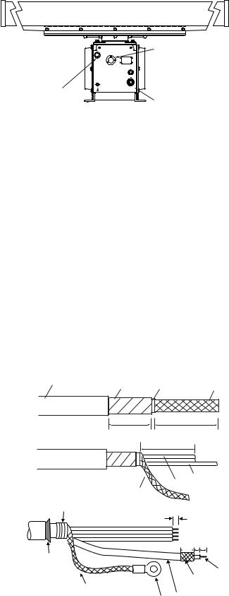
2.2 Antenna Unit
Gland for power cable (TPYCY-2.5)
Antenna safety switch
 Gland for HV cable (TYPCY-1.5)

 Cover (right side)
 Gland for signal cable (RW-9600) Ground terminal
Antenna unit, front view
Fabricating signal cable RW-9600 and HV cable TYPCY-1.5
1.Use a ratchet or box wrench (diagonal 13 mm) to open portand starboard-side covers on the antenna unit.
2.Unfasten the gland nut for the signal cable and remove the gasket, flat washers (3 pcs.) and gland cap. (The gland cap may be discarded.)
3.Fabricate the signal cable as follows:
a)Remove the vinyl sheath, armor and sheath by the amounts shown in the figure below.
b)Unravel the shield to expose cores.
c)Shorten cores (except coax) considering their locations on the terminal inside the antenna unit.
d)Shorten the shield, leaving 140 mm. Attach crimp-on-lug (FV5.5-4, yellow, φ4) to shield.
e)Remove the sheath of cores by 6 mm.
f)Unravel armor.
g)Fix vinyl wire, coaxial cable and shield by taping the shield with vinyl tape at the location shown below.
Vinyl |
Armor |
Sheath |
Shield |
|
sheath |
|
|
|
|
|
20 mm |
|
350 mm |
|
|
5 mm |
|
|
|
|
|
330 mm |
|
|
|
|
|
Coaxial cable |
|
|
Shield |
|
Vinyl wire |
|
|
|
|
|
|
Taping |
|
|
6 |
|
|
|
|
|
|
|
|
|
14 5 9 |
|
Unravel armor. |
|
|
|
Core |
|
|
|
|
|
|
Shield |
|
Fold back shield. |
|
|
|
Coaxial cable |
||
|
Crimp-on lug |
|||
|
|
|
||
Fabricating signal cable RW-9600
2-2
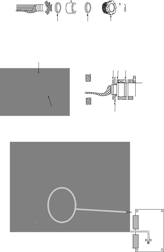
4.In the order shown in the figure below, pass the gland nut, flat washers (3 pcs.) and gasket onto the signal cable.
Armor |
|
Gasket |
|
|
|
|
|
Signal cable |
||||||||||||||
|
|
|
|
|
|
|
|
|
|
|
|
|
|
|
|
|
|
|
|
|
|
|
|
|
|
|
|
|
|
|
|
|
|
|
|
|
|
|
|
|
|
|
|
|
|
|
|
|
|
|
|
|
|
|
|
|
|
|
|
|
|
|
|
|
|
|
|
|
|
|
|
|
|
|
|
|
|
|
|
|
|
|
|
|
|
|
|
|
|
|
|
|
|
|
|
|
|
|
|
|
|
|
|
|
|
|
|
|
|
|
|
|
|
|
Flat washer |
Flat washer Gland nut |
(2)(1)
5.As shown in the figure below, fold back the armor onto flat washer (2) and insert remaining armor through flat washer (3). Cut off the part of the armor that protrudes past the flat washers
(2)and (3).
Fold back armor |
|
Flat washer |
|||||||||||||
|
|
||||||||||||||
|
(3)(2) |
(1) |
|
|
|
|
|||||||||
|
|
|
|
|
|
|
|
|
|
|
|
|
|
|
|
|
|
|
|
|
|
|
|
|
|
|
|
|
|
|
|
|
|
|
|
|
|
|
|
|
|
|
|
|
|
|
|
|
|
|
|
|
|
|
|
|
|
|
|
|
|
|
|
|
|
|
|
|
|
|
|
|
|
|
|
|
|
|
|
|
|
|
|
|
|
|
|
|
|
|
|
|
|
|
|
|
|
|
|
|
|
|
|
|
|
|
|
|
|
|
|
|
|
|
|
|
|
|
|
|
|
|
|
|
|
|
|
|
|
|
|
|
|
|
|
|
|
|
|
|
|
|
|
|
|
|
|
|
|
|
|
|
|
|
|
|
|
|
|
|
|
|
|
|
|
|
|
|
|
|
|
|
|
|
|
|
|
|
|
|
|
|
|
|
|
|
|
|
|
|
|
|
|
|
|
|
|
|
|
|
|
|
|
|
|
|
|
Flat washer (2)
Cut off armor that protrudes past flat washer.
6.Lead the signal cable through its cable gland and then into the chassis. Coat the threaded part of gland nut with sealant (supplied) and then tighten the nut.
Gland for HV  cable (TPYCY-1.5)
Gland for  signal cable (RW-9600)
|
TB Board |
|
TB801 |
|
Coaxial |
Connect shield of signal cable here. |
TB803 cable |
|
TB802 |
|
Fastening coaxial cable |
Antenna unit, front view
2-3
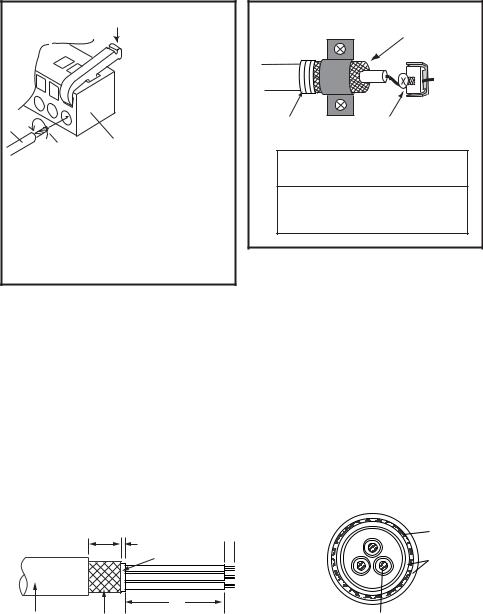
7.Using the terminal opener provided, connect cores (except coaxial cable) to their appropriate locations on TB801 on the TB Board. Refer to the interconnection diagram for wiring details.
8.Connect the coaxial cable to TB802, referring to the right-hand illustration below..
Wiring WAGO connector
Push down.
 Terminal opener
Wire
WAGO connector Twist
Procedure
1.Twist core.
2.Insert terminal opener as shown and push down.
3.Insert core into hole.
4.Release terminal opener.
5.Pull wire to confirm that it is firmly in place.
Fastening coaxial cable
Fasten shield by clamp.
Taping |
Fasten conductor with screw. |
|
NOTICE
Fasten BARE conductor. Do not use crimp-on lug, to prevent increased contact resistance.
How to wire WAGO connector
9.Attach crimp-on lug (FV5.5-4) to the shield of the signal cable and fasten it with the screw at the location specified in the illustration on the preceding page.
10.Process unused cores as follows:
a)Slip shrink tubing onto cores and heat.
b)Bind unused cores with cable tie.
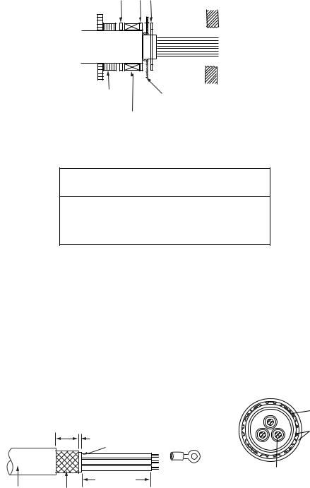
11.Unfasten the gland nut for the HV cable and remove gasket, flat washers (3 pcs.) and gland cap. (The gland cap may be discarded.)
12.Fabricate the HV cable as shown below.
20 mm |
6 |
Armor |
5 mm |
|
|
|
|
|
Sheath |
|
Sheath |
L |
|
|
Vinyl |
Armor |
Conductor |
|
sheath |
L: 300 mm (red) |
S = 1.50 mm2 |
|
φ = 1.56 mm |
|||
|
|||
|
L: 370 mm (black, white) |
|
|
|
|
SECTIONAL VIEW |
How to fabricate HV cable TYPCY-1.5
2-4
13.In the order shown in the figure below, pass the gland nut, flat washers (3 pcs.) and gasket onto the HV cable.
14.As shown in the figure below, fold back the armor onto the flat washer and insert it thru the other flat washer. Cut off the part of the armor that protrudes past the washer.
Flat washer
(1) (2) (3)
HV cable
Gland nut |
|
|
|
|
|
|
Cut off armor that |
|
|
|
|
|
|
||
|
|
|
|
|
|
||
|
|
|
|
|
|
||
|
|
|
|
|
|
|
protrudes past washer. |
|
Gasket |
||||||
15.Pass the HV cable through its cable gland and tighten gland nut.
16.Using the terminal opener, connect wiring to TB901, referring to the interconnection diagram.
 CAUTION
High voltage is present at the No. 6 pin of TB901. Miswiring at this pin can damage the antenna unit.
17.Close the cover.
18.Seal the cable gland for the HV cable with putty.
Fabricating the power cable TYPCY-2.5
1.Use a ratchet or box wrench to open the port-side cover on the antenna unit.
2.Unfasten the gland nut for the power cable and remove gasket, flat washer (3 pcs.) and gland cap. (The gland cap may be discarded.)
3.Fabricate the power cable as shown below. Unravel the armor. Wrap sheath with vinyl tape to fix base of vinyl wire.
Armor |
25 mm |
Sheath |
|
5 mm |
|
Sheath |
FV2-4 |
Conductor |
|
230 mm |
S = 2.50 mm2 |
|
Vinyl sheath Armor |
φ = 2.01 mm |
|
SECTIONAL VIEW |
||
|
How to fabricate power cable TYPCY-2.5
2-5
4.In the order shown in the figure below, pass the gland nut, flat washers (3 pcs.) and gasket onto the power cable.
5.As shown in the figure below, fold back armor onto flat washer and insert it thru the other flat washer. Cut off part of armor that protrudes past flat washer..
Flat washer
(1) (2) (3)
Power cable
Gland nut |
|
|
|
|
|
|
Cut off armor that |
|
|
|
|
|
|
||
|
|
|
|
|
|
||
|
|
|
|
|
|
||
|
|
|
|
|
|
|
protrudes past washer. |
|
Gasket |
||||||
Passing flat washer, etc. onto HV cable
6.Pass the power cable though its cable gland and then tighten the gland nut..
7.Pass the power cable to the rear of the antenna unit.
Terminal for power cable
Cable gland for power cable (TPYCY-2.5)
Antenna unit, left-side view
8.Connect the power cable to its terminal, referring to the interconnection diagram.
9.Close the cover.
10.Seal the cable gland for the power cable with putty.
2-6
Loading...