


 Loading...
C
9 - 5 2 , A s h i h a r a - c h o , N i s h i n o m i y a , J a p a n
T e l e p h o n e : |
0 7 9 8 - 6 5 - 2 1 1 1 |
T e l e f a x : |
0 7 9 8 - 6 5 - 4 2 0 0 |
A l l r i g h t s r e s e r v e d .  Printed in Japan
P U B . N o . I M E - 3 4 0 7 0 - M
( T E N I ) |
F A R / F R - 2 8 3 5 S |
|
 Y o u r L o c a l A g e n t / D e a l e r
F I R S T E D I T I O N |
: |
A U G . 1 9 9 5 |
M |
: |
J U L . 3 , 2 0 0 1 |


TABLE OF CONTENTS
EQUIPMENT LISTS ............................................................................ |
v |
1. MOUNTING
1.1 |
Radiator Assembling Procedure ...................................................................................... |
1-1 |
1.2 |
Mounting Structures ........................................................................................................ |
1-3 |
1.3 |
Mounting the Antenna Unit on the Mounting Platform ................................................... |
1-4 |
1.4 |
Mounting the Display Unit .............................................................................................. |
1-8 |
1.5 |
Mounting the Separate Type Control Panel ..................................................................... |
1-9 |
2. CONNECTIONS
2.1 Antenna Unit Connections ............................................................................................... |
2-1 |
|
2.2 |
Display Unit Connections ................................................................................................ |
2-6 |
2.3 |
Changing Power Specifications ..................................................................................... |
2-13 |
2.4 |
Power Supply Unit ......................................................................................................... |
2-14 |
3. INITIALIZATION AND ADJUSTMENT
3.1 |
Menus for Initialization and Adjustment |
.........................................................................3-1 |
3.2 |
Heading Alignment .......................................................................................................... |
3-2 |
3.3 Adjusting Sweep Timing ................................................................................................. |
3-2 |
|
3.4 Adjusting Video Signal Level .......................................................................................... |
3-3 |
|
3.5 |
Suppressing Main Bang ................................................................................................... |
3-4 |
3.6 |
Confirming Tuning .......................................................................................................... |
3-4 |
3.7 |
Confirming Magnetron Heater Voltage ........................................................................... |
3-5 |
3.8 |
Initial Settings Menus ...................................................................................................... |
3-6 |
3.9 |
Setting the Function Keys ................................................................................................ |
3-8 |
3.10 Default of InitialSetting Menus ................................................................................... |
3-11 |
|
3.11 How to adjust ARP board ............................................................................................ |
3-12 |
|
3.12 Installation Check List ................................................................................................. |
3-14 |
|
4. INSTALLATION OF GYRO CONVERTER GC-8 (option)
4.1 |
General Procedure for Installing and Setting up the GYRO CONVERTER Board ........ |
4-1 |
4.2 |
Connection of External Power Supply ............................................................................ |
4-3 |
4.3 |
Confirming Gyrocompass Specifications ........................................................................ |
4-3 |
4.4 Changing Settings on the GYRO CONVERTER Board ................................................. |
4-4 |
|
4.5 |
Setting the Bearing on the Radar Display ........................................................................ |
4-8 |
iii

LIST OF INSTALLATION MATERIALS, ACCESSORIES AND SPARE PARTS
LIST OF INSTALLATION MATERIALS, ACCESSORIES AND SPARE PARTS
......................................................... L-1 to L-13
OUTLINE DRAWINGS
OUTLINE DRAWINGS ........................................................................................... |
D-1 to D-6 |
SCHEMATIC DIAGRAMS
SCHEMATIC DIAGRAMS ....................................................................................... |
S-1 to S-6 |
iv

EQUIPMENT LISTS
Complete set
No. |
Name |
Type |
Qty |
Remarks |
|
|
|
|
|
1 |
Scanner unit |
SN-36AF |
1 |
Antenna radiator |
|
|
|
|
|
|
|
SN-30AF |
|
|
|
|
|
|
|
|
|
RSB-0026 |
1 |
Scanner unit |
|
|
|
|
|
|
|
RSB-0031 |
|
|
|
|
|
|
|
|
|
RSB-0088 |
|
Scanner unit for HSC |
|
|
|
|
|
|
|
RSB-0089 |
|
|
|
|
|
|
|
|
|
RSB-0090 |
|
|
|
|
|
|
|
2 |
Display unit |
RDP-115 |
1 |
Pedestal mount type |
|
|
|
|
|
|
|
|
|
Tabletop type |
|
|
|
|
|
3 |
Accessories |
FP03-05710 |
1 set |
For built-in control unit, FP-03-05701, |
|
|
|
|
FP-03-05704, FP-03-05705, 03-133- |
|
|
|
|
1811 |
|
|
|
|
|
|
|
FP03-05730 |
|
For separate control unit, FP-03-05701, |
|
|
|
|
FP-03-05703, FP-03-05704, FP-03- |
|
|
|
|
05705, 03-133-1811 |
|
|
|
|
|
4 |
Installation materials |
CP03-14603 |
1 set |
For scanner unit |
|
|
|
|
|
|
|
CP03-14602 |
1 set |
For display unit |
|
|
|
|
|
|
|
CP03-13907 |
1 set |
For power supply unit |
|
|
|
|
|
5 |
Signal cable |
RW-6895 *15m* |
1 |
|
|
|
|
|
|
|
|
RW-6895 *20m* |
|
|
|
|
|
|
|
|
|
RW-6895 *30m* |
|
|
|
|
|
|
|
|
|
RW-6895 *60m* |
|
|
|
|
|
|
|
6 |
Spare parts |
SP03-11600 |
1 set |
SP03-10320, SP03-11301 |
|
|
|
|
|
7 |
Power Supply Unit |
PSU-004-70-23-S |
1 |
3ø, 200/200 VAC, 2.3A |
|
|
|
|
|
|
|
PSU-004-80-10-S |
|
3ø, 380/440 VAC, 1.0A |
|
|
|
|
|
v
Optional equipment
No. |
Name |
Type |
Code No. |
Remarks |
|
|
|
|
|
1 |
Hand grips |
OP03-70 |
008-423-420 |
For display unit |
|
|
|
|
|
2 |
M card fixing plate |
OP03-133 |
008-452-400 |
|
|
|
|
|
|
3 |
Hood |
FP03-0574 |
008-459-810 |
|
|
|
|
|
|
4 |
Display unit cover |
OP03-126 |
008-459-820 |
Tabletop w/built-in control unit |
|
|
|
|
|
|
|
OP03-127 |
008-459-760 |
Tabletop w/separate control unit |
|
|
|
|
|
|
|
OP03-128 |
008-459-890 |
Pedestal mount |
|
|
|
|
|
5 |
Display unit |
OP03-129-1 |
008-459-830 |
Converts from tabletop type/built-in |
|
conversion kit |
|
|
control unit to pedestal mount |
|
OP03-129-2 |
008-452-410 |
||
|
|
|
||
|
|
|
|
|
|
|
OP03-130-1 |
008-459-900 |
Converts from tabletop type/separate |
|
|
|
|
control unit to pedestal mount |
|
|
OP03-130-2 |
008-452-430 |
|
|
|
|
||
|
|
|
|
|
|
|
OP03-131 |
008-459-910 |
Converts from pedestal mount to tabletop |
|
|
|
|
type/built-in control unit |
|
|
|
|
|
|
|
OP03-132-1 |
008-459-920 |
Converts from pedestal mount to tabletop |
|
|
|
|
type/separate control unit |
|
|
OP03-132-2 |
008-452-450 |
|
|
|
|
||
|
|
|
|
|
6 |
Control panel |
OP03-134 |
008-461-340 |
For fastening separate type control unit to |
|
fixing plate |
|
|
a tabletop |
|
|
|
|
|
7 |
Video plotter |
RP-25 |
|
|
|
|
|
|
|
8 |
Gyro converter |
GC-8-2 |
008-446-520 |
With installation materials |
|
|
|
|
|
9 |
Interswitch |
RJ-7 |
|
|
|
|
|
|
|
10 |
External buzzer |
OP03-21 |
000-030-097 |
1 m, with connector |
|
|
|
|
|
11 |
Performance |
PM-50 |
|
|
|
monitor |
|
|
|
|
|
|
|
|
12 |
Range unit |
OP03-110-1 |
008-446-610 |
To km |
|
conversion kit |
|
|
|
|
|
|
|
|
13 |
Range unit |
OP03-110-2 |
008-452-200 |
To sm |
|
conversion kit |
|
|
|
|
|
|
|
|
14 |
Color display unit |
CD-141 |
|
|
|
|
|
|
|
15 |
Slave display unit |
FMD-8000 |
|
|
|
|
|
|
|
16 |
Transformer unit |
RU-1758 |
000-030-416 |
Converts 220 VAC to 100 VAC |
|
|
|
|
|
17 |
Transformer unit |
RU-1803 |
000-030-420 |
Converts 440 VAC to 100 VAC |
|
|
|
|
|
18 |
Interswitch |
RJ-8 |
|
|
|
|
|
|
|
19 |
Interface unit |
IF-2300 |
000-002-422 |
|
|
|
|
|
|
vi
vii
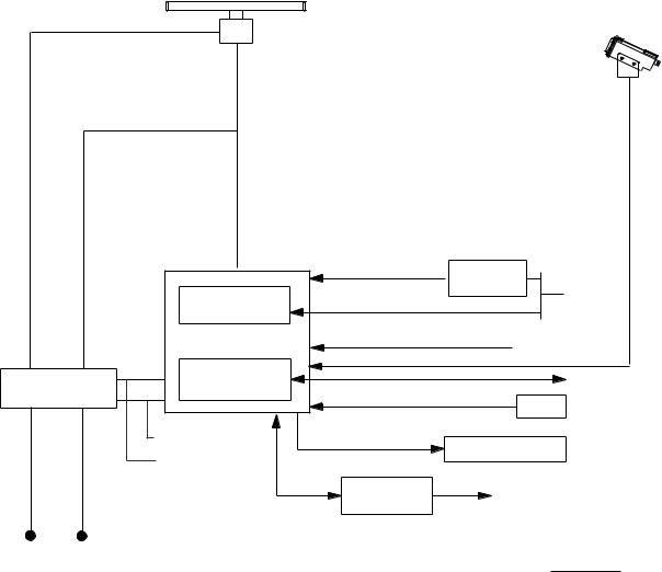
FR/FAR-2835S System Configuration
SCANNER ANTENNA
RSB-0026/0031
RSB-0088/0089/090 (For HSC)
Performance Monitor (option)
PM-50
|
|
|
|
DPYC(Y)-250V-3.5 |
|
RW-6895 |
|
115/230VAC, 1φ |
DPYC(Y)-250V -1.25 |
|
|
|
|
|
|
|
|
|
|
|
|
|
|
|
|
DISPLAY UNIT |
|
|
|
|
|
|
|
|
|
|
CO-SPEVV-SB-C |
Gyro Converter |
|
|
|
|
|
|
|
|
|
|
|
|
|
|
|
|
|
Gyro Interface GC-8 |
250V-MPYC(Y)-5 |
Gyro |
|
|
|
|
|
|
|
|
|
||
|
|
|
|
|
|
|
250V-DPYC(Y)-1.25 |
|
|
|
|
|
|
|
|
|
|
Speed Log |
|
|
|
|
Power Supply |
|
Video Protter RP-25 |
|
INS |
|
|
|
|
|
|
|
CO-SPEVV-SB-C |
|
|||
|
|
|
PSU-004 |
|
|
|
NAV |
|
|
|
scannerForunit |
-TPYC(Y)-250V3.5 |
-TPYC(Y)-660V3.5 |
unitdisplayFor |
DPYC(Y)-250V-3.5 |
|
|
|
|
|
250V-DPYC(Y)-3.5 |
2C 1.5 m |
External Buzzer |
|
|||||
|
|
|
|
|
|
|
|||
|
|
|
|
|
|
250V-MPYC(Y)-5 |
|
|
|
|
|
|
|
|
|
|
|
|
|
|
|
|
|
|
|
|
Interswitch |
Other Radar |
|
|
|
|
|
|
|
|
RJ-7/8 |
system |
|
|
|
|
|
|
|
|
|
|
|
Scanner unit |
|
|
|
|
|
|
|
|
|
220 VAC, 3φ , 50 Hz |
|
|
|
|
|
|
|
|
|
220 VAC, 3φ , 60 Hz |
|
|
|
|
|
|
|
|
|
380 VAC, 3φ , 50 Hz |
|
|
Display unit |
|
Optional Supply |
||||
440 VAC, 3φ , 60 Hz |
|
|
115/230 VAC, 1φ |
|
|||||
(For HSC)
220 VAC, 3φ , 50 Hz
220 VAC, 3φ , 60 Hz
440 VAC, 3φ , 60 Hz


1.3 Mounting the Antenna Unit on the Mounting Platform
 CAUTION
1)Work at high places is dangerous. Always wear a hard hat and safety belt when working on the antenna unit mast.
2)Both a service platform and steps to the service platform must be mounted to provide safe access for service personnel. Improperly installed platforms present a hazard to service personnel.
Siting considerations
CAUTION
A magnetic compass will be affected if placed too close to the antenna unit. Below are the minimum safe distances for magnetic cpmpassis.
Antenna |
Standard |
Steering |
|
Compass |
Compass |
RSB-0026 |
4.8 m |
3.6 m |
RSB-0031 |
||
|
|
|
RSB-0088 |
|
|
RSB-0089 |
|
|
RSB-0090 |
|
|
|
|
|
Consider the following points when selecting a mounting location for the antenna unit.
¥No funnel, mast or derrick should be within the vertical, beam width of the antenna in
the bow direction, especially zero degrees –5° , to prevent blind sectors and false echoes on the radar picture.
¥Fumes from the funnel or other exhaust vent can adversely affect performance and hot gas can distort the radiator. The antenna
unit must not be mouonted in a place where the temperture may exceed 70° C.
¥Leave sufficient space around the unit for maintenance ans servicing. See the antenna unit outline drawing for recommended maintenance space.
¥Locate the unit well away from the aerial of a radiotelephone or navigation receiver to prevent interference. Separation of more than two meters is recommended.
1 - 4


1.4 Mounting the Display Unit
The display unit is designed to be mounted on a tabletop or a pedestal (option).
Before mounting the display unit
If Gyro Converter GC-8 (option) is to be used, install and setup the GYRO PROCESSOR Board before mounting the display unit, because of the difficulty involved if done after the unit is mounted, Insstrutions for installtion and setup are in Chapter 4.
Siting considerations
Lpcate the display unit on the bridge in a place where it can be viewed and operated conveniently. In addition, consider the points noted in the figure which follows.
CAUTION
A magnetic compass will be affected if placed too close to the display unit. The minimum compass safe distances for magnetic compasses are
standard compass: 2.7 m steering compass: 1.8 m
Consider the points mentioned below when selecting a mounting location for the display unit.
¥The orientation of the display unit should
be so the operator views the screen while facing the bow. This makes determination of position much easier.
¥The location should be free of water spray.
¥The daylight bright type radar display sunlight. However, locate the unit out of direct sunlight and away from heat sources because of heat that can build up inside the cabinet.
¥The mounting location should be determined consiering the lengt of the signal cable between the antenna unit and the display unit. (The signal cable comes in lengths of 15, 20 or 30 meters; maximum 100 meters.)
¥Leave sufficient space around the unit for maintenance and servcing. See the display unit ouline drawing forrecommended maintenance space.
1 - 8

2. CONNECTIONS
2.1 Antenna Unit Connections
Two cables run between the display unit and the antenna unit, the signalcable and the antenna cable.
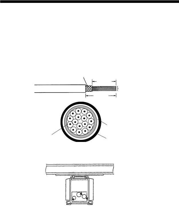
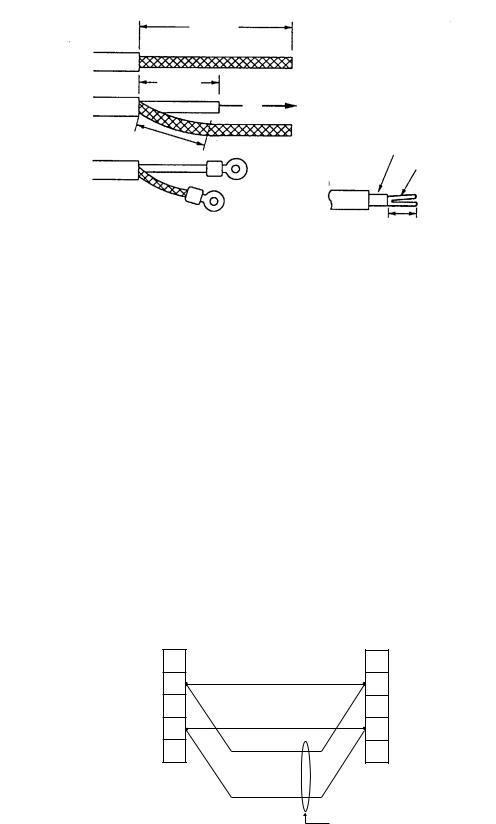
Fabricating antenna cable 660V-MPYCY-12/250V-MPYCY-12 (JIS cable)
1.Shorten the cable making the length from the cable gland to the cable end inside the scanner unit 450 mm. Remove the vinyl sheath of the cable by 450 mm; the armor by 440 mm.
Armor
440 mm
Conductors
|
450 mm |
|
Armor |
Core |
Vinyl sheath |
φ = 1.25 mm2 |
Figure 2-1 Fabrication of multicore cable 660V-MPYCY-12/250V-MPYCY-12
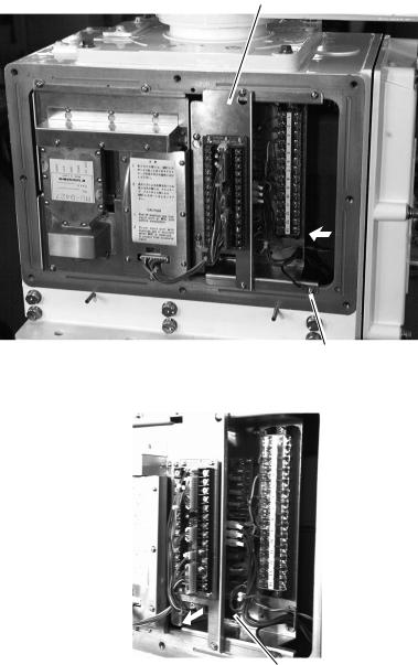
2. Turn off the ANT MOTOR SW on the scanner unit.
Signal cable  (RW-6895)
 ANT MOTOR SW
 Multicore cable (250V-MPYCY-12 or 660V-MPYCY-12)
Figure 2-2 Scanner unit, bow view
3.Open the left side cover on the scanner unit with the hex wrench (Supplied).
4.Unfasten the cable gland for the multicore cable and remove the gasket and flat washers.
5.As shown in Figure 2-3, slide the clamping gland, flat washers and gasket on the multicore cable.
2 - 1
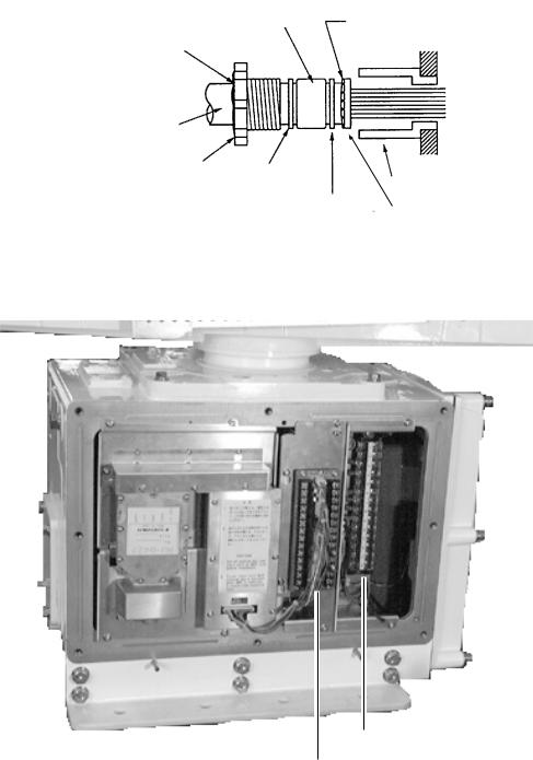
6. Fold back armor by 5 mm and pass it through the two flat washers as shown in Figure 2-3.
Gasket |
Armor (folded back) |
|
Seal with putty after tightening.
Vinyl sheath
Clamping gland
Flat |
|
|
Cable gland |
washer |
|
|
|
Flat |
|
|
|
|
|
Flat |
|
|
|
||
|
|
|
|
|
washer |
||
|
washer |
||
|
|
|
|
Figure 2-3 Passing clamping gland, washers and gasket on the multicore cable
7. Shorten conductors considering their locations on the terminal board STB-1.
STB-1
RTB-801
Figure 2-4 Scanner unit, port side view
8.Confirm that armor is grounded between two flat washers.
9.Remove the sheath of each conductor by 6 mm. Fix crimp-on lugs (FV1.25-4, blue, ø4) to each conductor. Make sure each connection is secure both electrically and mechanically.
10.Tighten the clamping gland.
11.Seal the cable gland with putty.
12.Connect the conductors to terminal board STB-1 referring to the interconnection diagram on page S-1.
2 - 2
Fabricating signal cable RW-6895
13.At the signal cable gland on the scanner unit, unfasten the clamping gland and remove gasket and flat washers.
14.Shorten the signal cable making the length from the cable gland to the cable end 500 mm. Remove the vinyl sheath by 550 mm; the armor by 540 mm.
|
|
Approx. 550 mm |
|
|
|
|
|
|
|
|
Inner shield |
Anti-corrosive |
Armor |
|
|
|
Outer shield |
|
|
|
|
||
vinyl sheath |
|
|
|
|
|
|
|
|
|
|
|
|
|
|
Approx. 540 mm |
|
|
Figure 2-5 Fabricating the signal cable RW-6895
15.Unravel the outer shield with a screwdriver or similar tool to expose the cores beneath the outer shield. Similarly, expose the cores beneath the inner shield. Mark all cores for future identification.
16.As shown in Figure 2-6, slide the clamping gland, washers and gasket onto the signal cable. Fold back the armor by 5 mm, and then pass it through the two flat washers.
Gasket
Armor
Seal with putty after tightening.
Clamping gland |
|
|
|
|
|
|
|
||
Washer |
Gland body |
|||
|
||||
|
|
|
||
|
|
|
Washer |
|
Figure 2-6 Passing clamping gland, washers and gasket on signal cable
17.Unfasten the terminal board RTB-801.
18.Pass the signal cable behind the terminal board plate for cable MPYCY-12, and then pass it through the locking wire saddle.
2 - 3
Terminal board fixing plate for RTB-801
Ground terminal
Figure 2-7 Scanner unit, rear view
Locking wire saddle
Figure 2-8 Scanner unit, rear view
19. Fasten the terminal board fixing plate for RTB-801.
2 - 4
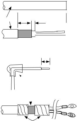
20.Route the signal cable beneath the lower left side of the terminal board fixing plate for the RTB-801. Shorten conductors of the signal cable considering their locations on the RTB801.
75 mm
Coaxial cable
2C-2V
50 mm
Fold back the conductor as illustrated below.
45 mm |
|
Inner core |
|
Conductor
Crimp-on lug FVD1.25-3  (Red, 3)
Crimp-on lug |
6 mm |
FV1.25-M3 |
|
(Red, 3) |
|
Figure 2-9 Fabrication of coaxial cable
21.Shorten the shield considering the distance to the ground terminal on the left side of the scanner unit chassis. (See Figure 2-7 for location.) Attach the crimp-on-lug FV5.5-4 (ø4, yellow) to the shield.
22.Remove approx. 6 mm of the vinyl insulation from the end of each conductor and fix the crimp-on lug FV1.25-M3 (Red) to each conductor. As shown in Figure 2-8, fold back the coaxial cable four times and attach the crimp-on-lug FVD1.25-3 (ø3, red). Attach the crimp- on-lug FVD1.25 (ø3, red) to the shield.
23.Tighten the clamping gland, and then seal the cable gland with putty.
24.Fasten the shield to the ground terminal on the scanner unit chassis.
25.Connect conductors to the terminal board RTB-801 referring to the interconnection diagram.
When the length of the signal cable is more than 150 m, remove the solder at terminal Nos. 24 (red) and 26 (black) on the DJ-1 connector. (#24 and #25 are spares.). Fasten the wires as shown below.
|
DJ-1 |
|
TB801 |
HEATER HOT |
14 |
YELLOW, LARGE |
14 |
|
|||
+12V |
16 |
WHITE, LARGE |
16 |
|
|||
|
|
RED, LARGE |
|
DISPLAY |
|
SCANNER |
|
|
UNIT |
BLACK, LARGE |
UNIT |
|
|
|
|
|
|
|
Length 150 m |
|
|
|
or more |
Figure 2-10 Wiring on terminal boards when length of signal cable is 150 m or more
26.Check for miswiring, loose screws. Grease the fixing bolts for the cover, gasket, and tap holes in the scanner chassis. Attach the cover.
2 - 5
When the De-Icer is installed
1)Before beginning any work on the scanner unit, turn off both the DE-ICER switch (S31) on the sub panel of the display unit and the breaker for the de-icer line at the main switchboard to remove the power (100 VAC, 1ø) to the de-icer. (Turning off the power to the display unit has no effect.)
2)The neck of the scanner unit becomes VERY HOT when the de-icer is working. (The deicer turns on when ambient temperature is below 0° C.)
2.2 Display Unit Connection
Two cables are terminated at the display unit: the signal cable RW-4839 or RW-6895 and the power cable. The signal cable, available in lengths of 15m, 20m, or 30m, comes with a connector preattached to it for connection to the display unit.
Fabricating power cable DPYCY-3.5
1) Remove the vinyl jacket by 150mm. |
(a) |
DPYCY-3.5 |
2)Cut off jute tape wrapped around the braided shield.
3)Unravel the braided shield to expose the cores by about 120mm.
4)Slip the terminal cap onto the core.
 Approx. 150 mm
Vinyl jacket |
15 mm |
|
5 mm |
(b) 


 Armor
Armor
5)Remove insulation of cores by about 10mm. Fix crimp-on lugs to the cores and braided shield.
6)Cover the braided shield with vinyl tape, leaving the portion which will lie inside the cable clamp untaped.
10 mm
(c)
Terminal cap
Clamp here
(d)
Taping
Figure 2-11 How to fabricate power cable DPYCY-3.5
2 - 6
Loading...