


 Loading...

#
#
#
#
#
#
#
#
#
#
#
#
#
#
#
#
#
#
#
#
#
#
#
#
#
# |
|
||
<R X U # / R F D O # $J H Q W 2 ' H D O H U # |
|||
|
|||
< 0 8 5 / # $ V K L K D U D 0 F K R / # |
|
||
1 L V K L Q R P L \D / # - D S D Q # |
|
||
7H O H S K R QH = # |
3 : < ; 0 9 8 0 5 444 # |
|
|
7H O H I D [= # |
3 : < ; 0 9 8 0 7 5 3 3 # |
|
|
|
|
|
|
$OO# ULJKWV# UHVHUYHG1 # |
3ULQWHG#LQ#-DSDQ# |
) ,5 6 7# ( ' ,7,2 1 # |
= # |
6 ( 3 # 4 < < 6 # |
||
# |
+ # |
= # |
1 2 91 # 4 8 / # 4 < < < # |
|||
|
|
|||||
|
38%1 # 1R1 # 20(0 5 6 7 8 3 # |
+ '$0 ,, # |
) & 90 9 9 : # |
|
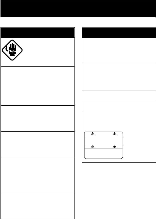

 SAFETY INSTRUCTIONS
 WARNING
ELECTRICAL SHOCK HAZARD
Do not open the equipment.
Only qualified personnel should work inside the equipment.
Immediately turn off the power at the switchboard if water leaks into the equipment or something is dropped in the equipment.
Continued use of the equipment can cause fire or electrical shock. Contact a FURUNO agent for service.
Do not disassemble or modify the equipment.
Fire, electrical shock or serious injury can result.
Do not place liquid-filled containers on the top of the equipment.
Fire or electrical shock can result if a liquid spills into the equipment.
Immediately turn off the power at the switchboard if the equipment is emitting smoke or fire.
Continued use of the equipment can cause fire or electrical shock. Contact a FURUNO agent for service.
Make sure no rain or water splash leaks into the equipment.
Fire or electrical shock can result if water leaks in the equipment.
 WARNING
Keep heater away from equipment.
A heater can melt the equipment's power cord, which can cause fire or electrical shock.
Use the proper fuse.
Fuse rating is shown on the equipment. Use of a wrong fuse can result in damage to the equipment.
 CAUTION
A warning label is attached to the equipment. Do not remove the label. If the label is missing or illegible, contact
a FURUNO agent or dealer.
WARNING |
Name: Warning Label (1) |
|
Type: 86-003-1011-0 |
||
To avoid electrical shock, do not |
||
remove cover. No user-serviceable |
Code No.: 100-236-230 |
|
parts inside. |
|
i

TABLE OF CONTENTS
INTRODUCTION ................................................ |
iii |
|
PRINCIPLE OF OPERATION.............................. |
v |
|
SYSTEM CONFIGURATION .............................. |
vi |
|
1. CONTROLS, INDICATIONS........................ |
1-1 |
|
1.1 |
Control Description ............................. |
1-1 |
1.2 |
Indications .......................................... |
1-2 |
2. BASIC OPERATION.................................... |
2-1 |
|
2.1 |
Turning the Power On/Off ................... |
2-1 |
2.2 |
Adjusting Brilliance.............................. |
2-1 |
2.3 |
Display Mode Selection, Description ... |
2-1 |
2.4 |
Adjusting Gain .................................... |
2-6 |
2.5 |
Automatic Operation ........................... |
2-6 |
2.6 |
Selecting Picture Advance Speed ....... |
2-7 |
2.7 |
Display Range Selection ..................... |
2-7 |
2.8 |
Erasing Weak Echoes......................... |
2-8 |
2.9 |
Measuring Depth to a Fish School....... |
2-9 |
2.10 |
A-scope Display.................................. |
2-9 |
2.11 |
Menu Operation ................................ |
2-10 |
2.12 |
Suppressing Interference .................. |
2-13 |
2.13 |
Suppressing Low Level Noise ........... |
2-13 |
2.14 |
Selecting Background |
|
|
and Echo Colors ............................... |
2-14 |
2.15 |
Alarms .............................................. |
2-14 |
2.16 |
White Marker .................................... |
2-16 |
2.17 |
Demonstration Picture....................... |
2-16 |
2.18 Correcting Speed/Water Temperature |
||
|
Readout ............................................ |
2-17 |
3. INTERPRETING THE DISPLAY................... |
3-1 |
|
3.1 |
Zero Line ............................................ |
3-1 |
3.2 |
Fish School Echoes ............................ |
3-1 |
3.3 |
Bottom Echo ....................................... |
3-1 |
3.4 |
Surface Noise/Aeration ....................... |
3-2 |
4. MAINTENANCE, TROUBLESHOOTING ..... |
4-1 |
|
4.1 |
Maintenance ....................................... |
4-1 |
4.2 |
Basic Troubleshooting......................... |
4-3 |
4.3 |
Diagnostics ......................................... |
4-4 |
4.4 |
Transducer Check ............................... |
4-5 |
4.5 |
Speed/Water Temperature |
|
|
Sensor (option) Check......................... |
4-5 |
4.6 |
Restoring Default Settings................... |
4-5 |
MENU TREE ................................................... |
A-1 |
|
SPECIFICATIONS......................................... |
SP-1 |
|
INDEX |
|
|
ii

INTRODUCTION
Congratulations on your choice of the FURUNO FCV-667 Color Video Sounder. We are confident that you will enjoy many years of operation with this fine piece of equipment.
For over 50 years FURUNO Electric Company has enjoyed an enviable reputation for quality and reliability throughout the world. This dedication to excellence is furthered by our extensive global network of agents and dealers.
The FCV-667 is just one of the many FURUNO developments in the field of echo sounding. The compact, lightweight but rugged unit is easy to install and operate and is suitable for both fresh and saltwater applications.
This unit is designed and constructed to withstand the rigors of the marine environment. However, to obtain optimum performance from this unit, you should carefully read and follow the recommended procedures for operation and maintenance. No machine can perform to the utmost of its ability unless it is installed, operated and maintained properly.
We would appreciate feedback from you, the end-user, about whether we are achieving our purposes.
Thank you for considering and purchasing FURUNO equipment.
Features
The FCV-667 dual-frequency (50kHz and 200kHz) color video sounder has a large variety of functions, all contained in a splash-proof rugged plastic case that is compact to fit small boats.
The principal features of the FCV-667 are
•User-friendly design for simplified operation.
•A wide variety of display modes: bottom-lock expansion, marker zoom and unique bottom zoom displays.
•Potent 300 W transceiver.
•8-color presentation (including background) on a 6" diagonal CRT, providing vivid presentation of underwater conditions.
•AUTO function permits unattended range and gain setting operations. The range scale and gain change automatically so that the bottom is displayed in reddish brown or red on the lower half of the screen.
•A-scope display gives excellent bottom fish discrimination, vital for bottom trawler and lobster/crab potter.
•Digital and analog displays of navigational data.
iii
•Alarms: fish, bottom, water temperature (requires appropriate sensor).
•Six pulselengths for excellent performance on both shallow and deep ranges.
•Universal 12-24 VDC power supply drawing 30 W of power at maximum.
•Water temperature/speed sensor optionally available.
iv
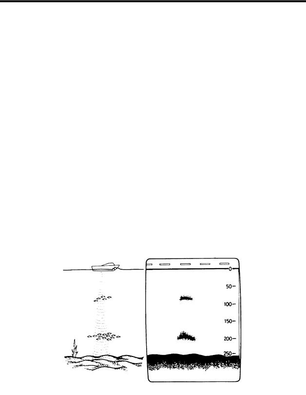
PRINCIPLE OF OPERATION
This Color Video Sounder determines the distance between its transducer and underwater objects such as fish, lake bottom or seabed and displays the results on a 6-inch color screen.
It does this by utilizing the fact that an ultrasonic wave transmitted through water travels at a nearly constant speed of 4800 feet (1500 meters) per second. When a sound wave strikes an underwater object such as fish or sea bottom, part of the sound wave is reflected back toward the source. Thus by calculating the time difference between the transmission of a sound wave and the reception of the reflected sound wave, the depth to the object can be determined. In a sense an echo sounder can be thought of as being an extremely sophisticated and quick timer, since it is capable of resolving time differences shorter than one thousandth of a second.
The entire process begins in the display unit. Transmitter power is sent to the transducer as a short pulse of electrical energy. The electrical signal produced by the transmitter is converted into an ultrasonic signal by the transducer and transmitted into the water. Any reflected signals from intervening objects (such as a fish school) are received by the transducer and converted back into an electrical signal. It is then amplified in the amplifier section, and finally, displayed on the screen.
The picture displayed by the color video sounder is made up of a series of vertical scan lines, one for each transmission. Each line represents a "snapshot" of what has occurred beneath the boat. The series of snapshots are accumulated side by side across the screen, and the resulting contours of the bottom and fish between the bottom and surface are displayed. The amount of history of objects that have passed beneath the boat over a series of transmission varies from less than a minute to a few minutes, depending on how you adjust the unit.
v
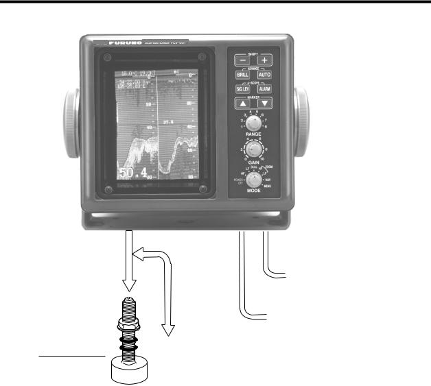
SYSTEM CONFIGURATION
DISPLAY UNIT
CV-667
TRANSDUCER
Standard supply 520-5PSC-A
Optional supply 520-5PWC 520-5MSC-A 520ST-PWA 524ST-MSA
Ship's mains 12-24 VDC
External equipment (GPS navigator, etc.)
SPEED, TEMPERATURE SENSOR (option)
Speed/temperature sensor ST-02MSB
ST-02PSB
ST-01PTB
Temperature sensor
T-02MTB
T-02MSB
T-03MSB
vi
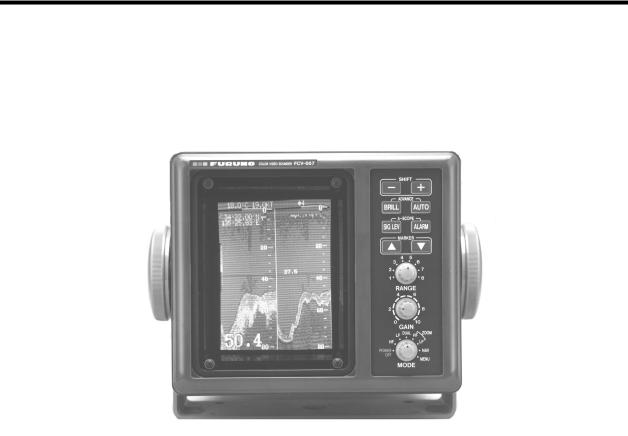
1.CONTROLS, INDICATIONS
1.1Control Description
The equipment is so designed that even a first time user can quickly become acquainted with the operating procedure. Operation of each control or key is acknowledged by an alphanumeric message or symbol indication on the screen.
|
|
|
|
|
|
|
|
|
|
|
|
|
|
Control |
|
|
|
|
Function |
|
|
|
|
|
|
||
SHIFT-, SHIFT+ |
|
• Change display start depth. |
||||
(Appears in text as [-], [+].) |
|
• Select options on menus. |
||||
|
|
|
|
|
||
BRILL |
|
Adjusts brilliance of display. |
||||
|
|
|
|
|
||
AUTO |
|
Turns the automatic sounder adjustment feature on/off. |
||||
|
|
|
|
|
||
ADVANCE (BRILL + AUTO) |
|
Pressing the BRILL and AUTO keys together selects display |
||||
|
|
|
advancement speed. |
|||
|
|
|
|
|
||
SIG LEV |
|
Eliminates low intensity echoes (up to light-blue echoes) in two |
||||
|
|
|
steps. |
|||
|
|
|
|
|
||
ALARM |
|
Opens/closes the alarm menu. |
||||
|
|
|
|
|
||
A-SCOPE (SIG LEV + ALARM) |
|
Pressing the SIG LEV and ALARM keys together displays the |
||||
|
|
|
A-scope display at the right 1/4 of the screen. |
|||
|
|
|
|
|
||
MARKER ▲, MARKER ▼ |
|
• Shift the Variable Range Marker (VRM). |
||||
(Appears in text as [▲] or [▼].) |
|
• |
Set alarm zone. |
|||
|
|
|
• |
Select menu items. |
||
|
|
|
• |
Set white marker. |
||
|
|
|
|
|
||
RANGE |
|
Sets the basic range of the display. |
||||
|
|
|
|
|
||
GAIN |
|
Adjusts receiver sensitivity. |
||||
|
|
|
|
|
|
|
MODE |
|
• |
Turns unit on/off. |
|||
|
|
|
• |
Selects display mode. |
||
|
|
|
|
|
|
|
1-1
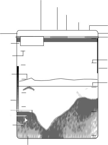
1.2Indications
Speed*
Noise Limiter
Picture Advance Speed
Signal Level
Alarm Type (F,B,TI,TB)
Water |
49.8˚F |
12.5kt |
NL1 |
ç1 |
SL1 |
F |
Active alarm |
temperature* |
35° 15.000' N |
|
|
|
0 |
Minute marker |
|
Nav data* |
135° 07.500' W |
|
|
|
|
(yellow, blue, |
|
|
70 |
|
|
|
|
|
30 sec. each) |
Water temperature |
|
|
|
|
|
|
|
|
|
|
|
|
|
Range scale |
|
scale* |
60 |
|
|
|
|
20 |
|
|
|
|
|
|
Alarm zone |
||
|
|
|
|
|
|
||
|
|
|
|
|
|
|
|
Water temperature |
|
|
|
|
|
|
marker |
marker* (Color |
50 |
|
|
|
|
|
|
changes with |
|
|
|
39.8 |
|
40 |
Variable range |
HUE setting.) |
|
|
|
|
|||
|
|
|
|
|
marker (green) |
||
|
40 |
|
|
|
|
|
w/depth readout |
Color |
|
|
|
|
|
|
|
bar |
30 |
|
|
|
|
|
|
Demonstration Mode |
|
|
|
|
60 |
|
|
|
|
|
|
|
|
||
Alarm Icon |
|
|
|
|
|
|
|
|
|
|
|
|
|
All indications and |
|
|
(DEMO) |
|
|
|
|
||
Auto Setting |
|
|
|
|
markers are displayed |
||
AUTO-1 |
|
|
|
|
|||
|
|
|
|
in white unless |
|||
|
49.6 |
|
|
|
|
||
|
|
|
|
80 |
noted otherwise. |
||
|
|
|
|
|
|||
Depth |
* Requires appropriate sensor. |
1-2
2.BASIC OPERATION
2.1Turning the Power On/Off
Turn the [MODE] switch clockwise to turn the power on. The unit starts with the settings used before it was turned off last time. Note that there is a few seconds delay prior to display of the picture until the CRT warms up. To turn the power off, turn the switch fully counterclockwise.
2.2Adjusting Brilliance
Use the [BRILL] key to adjust the brilliance. The selected brilliance level is shown on the display as below. There are six levels of brilliance including off. Keep the brilliance moderate to extend the life of the CRT.
BRILL: 0
2.3Display Mode Selection, Description
2.3.1Display mode selection
Seven display modes are available and you may select one of them with the [MODE] switch.
|
MODE switch description |
|
|
|
|
MODE Switch |
Function |
|
Position |
||
|
||
|
|
|
HF |
Provides the high frequency (200 kHz) normal picture on the full screen. |
|
|
|
|
LF |
Displays the low frequency (50 kHz) normal picture on the full screen. |
|
|
|
|
DUAL |
Displays the normal display for high frequency (200 kHz) on right half and that for |
|
|
the low frequency (50 kHz) on the left half. |
|
|
|
|
HF ZOOM |
Shows the normal display of the high frequency (200 kHz) on right half and its |
|
|
zoom display on the left half. |
|
|
|
|
LF ZOOM |
Provides the normal display of the low frequency (50 kHz) on right half and its |
|
|
zoom display on the left half. |
|
|
|
|
NAV |
Shows navigation data in analog or digital form (depending on menu setting) on |
|
|
the full screen. |
|
|
|
|
MENU |
Displays the main and system menus. |
|
|
|
2-1

2.3.2 Display mode description
HF, LF (high frequency, low frequency) mode
The sounder uses ultrasonic pulses to detect bottom conditions. The lower the frequency of the pulse the wider the detection area. Therefore, the 50 kHz frequency is useful for general detection and judging bottom conditions, while the 200 kHz frequency is useful for detailed observation of fish schools.
0.00
Fish |
20 |
school |
|
40
Bottom
60

 49.6
49.6


 80
80

DUAL frequency mode
This mode provides the 50 kHz picture on the left-half of the screen and the 200 kHz on the right half, and is useful for detecting fish schools which have different reflection characteristics with frequency. For example, a school of tiny fish like minnow returns stronger echoes on a high frequency compared to a low frequency.
0 |
0.0 |
0 |
50 kHz |
200 kHz |
|
picture |
picture |
|
20 |
|
20 |
40 |
|
40 |
60 |
|
|
49.6 |
|
80 |
2-2
Loading...