


 Loading...
Back
UAIS TRANSPONDER
FA-100
PRINTED IN JAPAN
9-52 Ashihara-cho,
Nishinomiya, 662-8580, JAPAN
Telephone : |
0798-65-2111 |
|
Fax |
: |
0798-65-4200 |
All rights reserved. |
Printed in Japan |
Pub. No. IME-44170-H5
( AKMU ) FA-100
The paper used in this manual is elemental chlorine free.
FURUNO Authorized Distributor/Dealer
FIRST EDITION : SEP. 2002
H5 : OCT. 17, 2005
*00080932513*
*00080932513*
* 0 0 0 8 0 9 3 2 5 1 3 *

 SAFETY INSTRUCTIONS
 WARNING
ELECTRICAL SHOCK HAZARD
Do not open the equipment unless totally familiar with electrical circuits and service manual.
Only qualified personnel should work inside the equipment.
Turn off the power at the switchboard before beginning the installation.
Fire or electrical shock can result if the power is left on.
Do not install the equipment where it may get wet from rain or water splash.
Water in the equipment can result in fire, electrical shock or damage the equipment.
Be sure that the power supply is compatible with the voltage rating of the equipment.
Connection of an incorrect power supply can cause fire or damage the equipment. The voltage rating of the equipment appears on the label above the power connector.
 CAUTION
Observe the following compass safe distances to prevent interference to a magnetic compass:
|
Standard |
Steering |
|
compass |
compass |
|
|
|
FA-100 |
1.0 m |
0.6 m |
|
|
|
CB-100 |
0.6 m |
0.4 m |
|
|
|
GVA-100 |
0.3 m |
0.3 m |
|
|
|
DB-1 |
0.3 m |
0.3 m |
|
|
|
PR-240-CE |
0.9m |
0.6 m |
|
|
|
Attach securely protection earth to the ship's body.
The protection earth is required to the power supply to prevent electrical shock
i

TABLE OF CONTENTS
SYSTEM CONFIGURATION................................................................................ |
iii |
|
EQUIPMENT LISTS ............................................................................................. |
iv |
|
1. MOUNTING ....................................................................................................... |
1 |
|
1.1 Antenna Unit.................................................................................................................... |
1 |
|
|
1.1.1 GPS antenna unit ............................................................................................... |
1 |
|
1.1.2 VHF antenna ...................................................................................................... |
3 |
|
1.1.3 GPS/VHF combined antenna .............................................................................. |
5 |
1.2 |
Transponder Unit............................................................................................................. |
8 |
1.3 |
Junction Box.................................................................................................................. |
10 |
1.4 |
Power Supply (option) ................................................................................................... |
11 |
1.5 |
Pilot Plug (option) .......................................................................................................... |
11 |
2. WIRING ........................................................................................................... |
12 |
|
3. INPUT/OUTPUT SIGNAL ............................................................................... |
15 |
|
3.1 |
Inputs from Sensors....................................................................................................... |
15 |
3.2 |
Input/Output of AIS Signal ............................................................................................. |
16 |
3.3 |
Input of Gyrocompass Signal......................................................................................... |
17 |
3.4 Alarm Signal Output....................................................................................................... |
17 |
|
3.5 |
LAN Input/Output........................................................................................................... |
18 |
3.6 |
Pilot Plug ....................................................................................................................... |
18 |
3.7 |
Jumper Setting in the Junction Box................................................................................ |
19 |
3.8 |
Input/Output Sentences................................................................................................. |
20 |
3.9 |
Changing Ship’s Mains Specifications............................................................................ |
21 |
4. SETTING AND ADJUSTMENT....................................................................... |
22 |
|
4.1 |
Setting MMSI, IMO No., Name and Call Sign ................................................................ |
22 |
4.2 |
Setting GPS Antenna Position and Ship’s Type ............................................................. |
24 |
4.3 |
System Settings............................................................................................................. |
26 |
PACKING LIST
OUTLINE DRAWINGS
INTERCONNECTION DIAGRAM
ii
SYSTEM CONFIGURATION
|
|
Either |
GPS antenna |
VHF whip antenna |
GPS/VHF |
GPA-017S |
|
combined antenna |
GSC-001 |
|
GVA-100 |
|
|
Distributor unit |
|
|
DB-1 |
|
|
Transponder unit |
|
|
FA-100 |
Power supply |
AD-100 |
PR-240-CE |
|
|
|
|
Ship’s mains |
24 VDC |
||
100-115/200-230 VAC |
|||
1f, 50/60Hz |
|
12-24 VDC |
|
Junction box CB-100
GPS Navigator *
Other external equipments
Gyrocompass
:Standard
:Option
:Local supply
*: External GPS Navigation is required.
Category of the units
GPA-017S |
Exposed to the weather |
GSC-001 |
Exposed to the weather |
GVA-100 |
Exposed to the weather |
FA-100 |
Protected from the weather |
CB-100 |
Protected from the weather |
DB-1 |
Protected from the weather |
PR-240-CE |
Protected from the weather |
iii

EQUIPMENT LISTS
Standard supply
No. |
Name |
Type |
Code no. |
Qty |
Remarks |
|
|
|
|
|
|
1 |
Transponder Unit |
FA-100 |
- |
1 |
|
|
|
|
|
|
|
2 |
Junction Box |
CB-100 |
- |
1 |
|
|
|
|
|
|
|
3 |
GPS Antenna |
GPA-017S |
- |
|
|
|
|
|
|
|
|
|
GPS Antenna |
GSC-001 |
- |
1 |
Select one. |
|
|
|
|
||
|
GPS/VHF Combined |
GVA-100* |
- |
||
|
Antenna |
|
|
|
|
4 |
Installation Materials |
CP24-00101* |
005-950-730 |
1 |
For DB-1 |
|
|
|
|
|
|
|
|
CP24-00102* |
005-950-700 |
1 |
For FA-100 |
|
|
|
|
|
|
|
|
CP05-08701* |
005-949-280 |
1 |
For CB-100 |
|
|
|
|
|
|
|
|
CP24-00121** |
005-952-350 |
1 |
For GPA-017S |
|
|
|
|
|
|
|
|
CP24-00141* |
005-952-330 |
1 |
For GVA-100 |
|
|
|
|
|
|
Optional supply |
**: for Japan only |
|||
|
|
|||
|
|
|
|
|
No. |
Name |
Type |
Code no. |
Remarks |
1 |
Antenna cable set |
CP20-01700(30m) |
004-372-110 |
For GPS or Combined antenna |
|
|
|
|
8D-FB-CV *30M*, CP20-01701 |
|
|
|
|
|
2 |
Antenna cable set |
CP20-01710(50m) |
004-372-120 |
For GPS or Combined antenna |
|
|
|
|
8D-FB-CV *50M*, CP20-01701 |
|
|
|
|
|
3 |
Flush mount kit A |
OP24-1 |
005-950-740 |
|
|
|
|
|
|
4 |
Flush mount kit B |
OP24-2 |
005-950-750 |
|
|
|
|
|
|
5 |
Mast mount fixture |
CP20-01111 |
004-365-780 |
For GPA-017S |
|
|
|
|
|
6 |
Right-angle |
No.13-QA330 |
000-803-239 |
For GPA-017S |
|
antenna base |
|
|
|
7 |
L-angle antenna |
No.13-QA310 |
000-803-240 |
For GPA-017S |
|
base |
|
|
|
8 |
Antenna base for |
No.13-RC5160 |
000-806-114 |
For GPA-017S |
|
rail mount |
|
|
|
9 |
VHF whip antenna |
FAB-151D |
000-572-029 |
For Japan only |
|
|
|
|
|
10 |
Antenna fixing |
4-310071 |
000-572-184 |
For FAB-151D |
|
bracket |
|
|
|
11 |
VHF whip antenna |
150M-W2VN |
000-113-498 |
For outside Japan |
|
|
|
|
|
12 |
Power supply |
PR-240-CE |
- |
Include installation materials |
|
|
|
|
CP24-00151* |
13 |
Pilot plug |
OP24-3 |
000-053-911 |
|
|
|
|
|
|
14 |
AD-100 |
AD-100 |
- |
For gyrocompass |
15 |
PC AIS |
OP24-24-1 |
005-954-420 |
CD-ROM, USB protect key |
|
software kit |
|
|
|
16 |
φ 80 Mast mount kit |
OP24-5 |
005-954-510 |
For Combined antenna |
|
|
|
|
|
*: Refer to packing list at the back of this manual.
iv
1. MOUNTING
1.1 Antenna Unit
1.1.1 GPS antenna unit
Install the GPS antenna unit referring to the drawing at the back of this manual D-1. When selecting a mounting location for the antenna, keep in mind the following points.
•Select a location out of the radar beam. The radar beam will obstruct or prevent reception of the GPS satellite signal.
•There should be no interfering object within the line-of-sight to the satellites. Objects within line-of-sight to a satellite, for example, a mast, may block reception or prolong acquisition time.
•Mount the antenna unit as high as possible to keep it free of interfering objects and water spray, which can interrupt reception of GPS satellite signal if the water freezes.
Extending antenna cable
Three types of antenna cable extensions are optionally available. a) Antenna cable set CP20-01700
Antenna Unit
0.6 m
1 m
|
Conversion |
|
|
: Connector |
||
|
Cable Assy. |
|
|
|
||
|
NJ-TP-3DXV-1 |
|
|
|
||
|
Antenna Cable |
|
|
|
|
FA-100 |
|
|
|
|
|
||
|
|
|
|
|
|
|
|
30 m |
|
|
1 m |
||
|
|
|
||||
Fabricate locally. (See next page.)
Waterproofing connector
Wrap connector with vulcanizing tape and then vinyl tape. Bind the tape end with a cable-tie.
Waterproofing connector
b)Antenna cable set CP20-01710 (8D-FB-CV, 50m)
Connect the cable the same as a) above.
c)Cable type RG-10U/Y (shipyard supply)
Note: The length of this cable should be less than 20 m to prevent signal loss. The coax. coupling cable assy.(type: NJ-TP+3DXV-1, code no. 000-123-809), coaxial connector(N-P-8DFB; supplied), vulcanizing tape and vinyl tape are required. Fabricate both ends of the cable as shown in the figure on the next page.
1
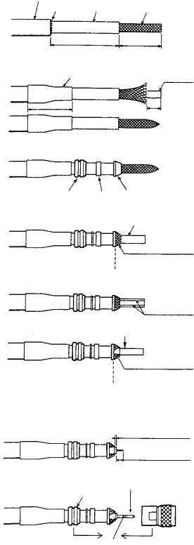
How to attach the connector N-P-8DFB for cable 8D-FB-CV
Outer Sheath |
Dimensions in millimeters. |
|
Armor |
Inner Sheath Shield |
|
|
50 |
30 |
Cover with heat-shrink tubing and heat.
Remove outer sheath and armor by the dimensions shown left.
Expose inner sheath and shield by the dimensions shown left.
Cut off insulator and core by 10mm.
30 |
10 |
Clamp |
Gasket Clamp |
Nut |
(reddish |
|
brown) |
|
Aluminum Foil |
Trim shield here.
Insulator
Trim aluminum tape foil here.
Twist shield end.
Ship on clamp nut, gasket and clamp as shown left.
Fold back shield over clamp and trim.
Cut aluminum foil at four places, 90° from one another.
Fold back aluminum foil onto shield and trim.
1
5
Pin
Clamp Nut
Shell
Solder through the hole.
Expose the insulator by 1mm.
Expose the core by 5mm.
Slip the pin onto the conductor. Solder them together through the hole on the pin.
Insert the pin into the shell. Screw the clamp nut into the shell.
(Tighten by turning the clamp nut. Do not tighten by turning the shell.)
How to attach connector N-P-8DFB
2
1.1.2 VHF antenna Location
Location of the mandatory AIS VHF-antenna should be carefully considered. Digital communication is more sensitive than analog/voice communication to interference created by reflections in obstructions like masts and booms. It may be necessary to relocate the VHF radiotelephone antenna to minimize interference effects.
To minimise interference effects, the following guidelines apply:
•The AIS VHF antenna should be placed in an elevated position that is as free as possible with a minimum of 0.5 meters in the horizontal direction from constructions made of conductive materials. The antenna should not be installed close to any large vertical obstruction. The objective for the AIS VHF antenna is to see the horizon freely through 360 degrees.
•The AIS VHF antenna should be installed safely away from interfering high-power energy sources like radar and other transmitting radio antennas, preferably at least 3 meters away from and out of the transmitting beam.
•There should not be more than one antenna on the same plane. The AIS VHF antenna should be mounted directly above or below the ship’s primary VHF radiotelephone antenna, with no horizontal separation and with a minimum of 2.8 meters vertical separation. If it is located on the same plane as other antennas, the distance apart should be at least 10 meters.
Cabling
•The cable should be kept as short as possible to minimize signal attenuation. Coaxial cables equal to or better than RG10U/Y are recommended.
•All outdoor installed connectors on coaxial cables should be fitted with preventive isolation such as vulcanizing tape to protect against water penetration into the antenna cable.
•Coaxial cables should be installed in separate signal cable channels/tubes and at least 10 cm away from power supply cables. Crossing of cables should be done at right angles (90°). The minimum bend radius of the coaxial cable should be 5 times the cable's outer diameter.
•Install the VHF whip antenna referring to the outline drawing at the back of this manual. Separate this antenna from other VHF radiotelephone antennas as shown on the next page to prevent interference to the FA-100.
3
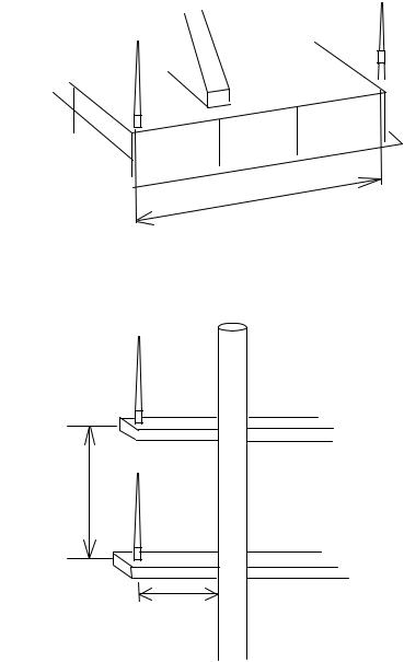
Horizontal separation distance
Other VHF whip antenna
Whip antenna for AIS (GPS/VHF combined antenna)
More than 10 m
Vertical separation distance
More than 2.8 m
More than 0.5 m
•When coaxial cable RG-10U/Y (shipyard supply) is used, attach the coaxial plug M-P-7 (dockyard supply) as shown on the next page.
4
How to attach the plug M-P-7
Lay the coaxial cable and attach an M-type plug (if necessary) to the cable as follows.
1.Remove the sheath by 30 mm.
2.Bare 23 mm of the center conductor. Trim braided shield by 5 mm and tin.
3.Slide coupling ring onto cable.
4.Screw the plug assembly on the cable.
5.Solder plug assembly to braided shield through solder holes. Solder contact sleeve to conductor.
6.Screw coupling ring into plug assembly.
30 mm
Sheath
5 mm 
 2 mm
2 mm
|
|
|
|
|
|
|
|
|
|
|
|
|
|
|
|
|
|
|
|
|
|
|
|
|
|
|
|
|
|
|
|
|
|
|
|
|
|
|
|
|
|
|
|
Conductor |
||||||
|
|
|
|
|
|
|
|
|
|
|||||||
|
|
Braided shield |
||||||||||||||
|
|
|
Insulator |
|||||||||||||
|
|
Plug assembly |
|
Contact sleeve |
||||||||||||
|
|
|
|
|
|
|
|
|
|
|
|
|
|
|
|
|
|
|
|
|
|
|
|
|
|
|
|
|
|
|
|
|
|
|
|
|
|
|
|
|
|
|
|
|
|
|
|
|
|
|
|
|
|
|
|
|
|
|
|
|
|
|
|
|
|
|
|
|
|
|
|
|
|
|
|
|
|
|
|
|
|
|
|
|
|
Solder both |
Cut conductor here. |
Coupling ring |
|
|
sides of hole. |
|
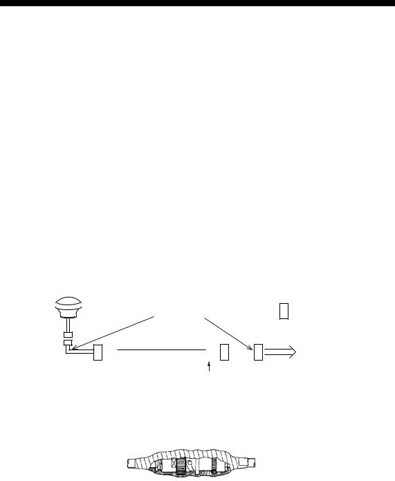
1.1.3 GPS/VHF combined antenna
Install the combined antenna unit referring to the outline drawing. When selecting a mounting location for the antenna, keep in mind the following points.
•Select a location out of the radar beam. The radar beam will obstruct or prevent reception of the GPS satellite signal.
•There should be no interfering object within the line-of-sight to the satellites. Objects within line-of-sight to a satellite, for example, a mast, may block reception or prolong acquisition time.
•Mount the antenna unit as high as possible. Mounting it this way keeps it free of interfering objects and water spray, which can interrupt reception of GPS satellite signal if the water freezes.
•Also, refer to the antenna installation guidelines page 3.
Outdoor Indoor
|
Distributor DB-1 |
|
GPS |
|
Transponder unit |
|
VHF |
N-P-8DFB |
N-P-8DFB |
|
RG-10U/Y |
Installation overview of GPS/VHF combined antenna
Note: Optional φ 80 mast mount kit (Type: OP24-5, Code no.: 005-954-510) is required to fix the GPS/VHF combined antenna to the mast (φ 60 - 80).
5
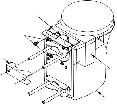
Mounting procedures
1.Dismount the bottom cover, cut the cable-tie inside the unit and take out the coaxial connector attached to the combined box.
2.Loosen four screws to loosen whip antenna fixture and pull out the coaxial connector coming from the combined box through the hole in the whip antenna fixture.
3.Connect the coaxial connector to the whip antenna base and wrap the junction part of the whip antenna with vulcanizing tape and then vinyl tape for waterproofing.
4.Insert the whip antenna from the top of the combined antenna.
5.Secure the whip antenna with whip antenna fixture.
6.Using a new plastic band (supplied), secure the cables and coaxial connector inside the antenna case.
7.Mount the bottom cover.
8.Fix the GPS/VHF combined antenna to the ship’s stanchion (40 to 50 mm diameter) with antenna fixing brackets, flat washers and hex. nuts.
Note: Coat the exposed parts of bolts and nuts with silicon sealant.
Whip antenna fixture
Loosen four screws. (M5x16)
Antenna fixing bracket
Combined box
Bottom cover
GPS/VHF Combined antenna
6
The top of the stanchion come into contact with the flange.
 Stanchion
Installing distributor unit DB-1
The length of the cable between the distributor unit and transponder unit is 1 m so locate the distributor unit within 1 m from the transponder unit. Fix the distributor unit on the bulkhead, facing the cable entrance downward. Remove the lid of the distributor unit and secure the unit with two tapping screws.
Tapping screw (4x30)
Note: Be sure no foreign material or water enters the distributor unit.
7
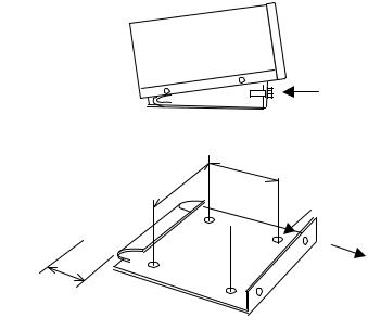
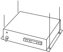
1.2 Transponder Unit
The transponder unit can be installed on a desktop or flush mounted in a panel. Install it on the chart table or near the steering place, referring to the outline drawing.
When selecting a mounting location for the transponder, keep the following in mind:
•Keep the transponder out of direct sunlight.
•The temperature and humidity should be moderate and stable. (Operating temperature range: -15°C to +55°C)
•Locate the unit away from exhaust pipes and vents.
•The mounting location should be well ventilated.
•Mount the unit where shock and vibration are minimal.
•Keep the unit away from electromagnetic field generating equipment such as motor, generator.
•For maintenance and checking purposes, leave sufficient space at the sides and rear of the unit and leave slack in cables. Refer to the outline drawing.
•A magnetic compass will be affected if the unit is placed too close to it. Observe the following compass safe distances to prevent disturbance to the magnetic compass:
Standard compass: 1.0 meters
Steering compass: 0.6 meters
Desktop mounting
1.Remove two hex. bolts from the lower part of the transponder unit and dismount the mounting base.
Remove two hex. bolts.
2. Fix the mounting base to the desktop with four tapping screws (6x20: supplied)
or hex. bolts.
120 mm
φ 8
Front
Service clearance
more than 130 mm
Mounting base
3.Place the transponder unit on the mounting base and secure it with two hex. bolts.
8
Flush mounting
Optional flush mount kit A or B is required for flush mounting. For mounting dimensions, refer to the outline drawing at the back of this manual.
Flush mount kit A: |
Type OP24-1 Code no. 005-950-740 |
|
|||
|
Name |
|
Type |
Code no. |
Qty |
|
|
|
|
|
|
1 |
Cosmetic panel |
|
24-003-2811 |
100-299-540 |
1 |
|
|
|
|
|
|
2 |
+Tapping screw |
|
5x25 |
000-802-082 |
4 |
|
|
|
|
|
|
1.Cut out a hole in the mounting location, referring to the outline drawing.
2.Remove two hex bolts to dismount the mounting base.
3.Remove six hex bolts from the bottom of the transponder unit to dismount the mounting pedestal.
4.Set the transponder unit to the cosmetic panel and fix them with six hex bolts.
5.Set the assembly (transponder unit and cosmetic panel) to the hole and fix it with four tapping screws (5x25).
Flush mount kit B: |
Type OP24-2 Code no. 005-950-750 |
|
|||
|
Name |
|
Type |
Code no. |
Qty |
|
|
|
|
|
|
1 |
Mounting bracket |
|
24-003-2821 |
100-299-550 |
1 |
|
|
|
|
|
|
2 |
Hex bolt |
|
M5x25 |
000-862-125 |
6 |
|
|
|
|
|
|
3 |
Hex nut |
|
M5 |
000-863-108 |
6 |
|
|
|
|
|
|
4 |
Flat washer |
|
M5 |
000-864-128 |
6 |
|
|
|
|
|
|
5 |
Spring washer |
|
M5 |
000-864-258 |
6 |
|
|
|
|
|
|
1.Cut out a hole in the mounting location, referring to the outline drawing.
2.Dismount the mounting base and mounting pedestal from the transponder unit.
3.Set the transponder unit to the hole. Using six hex bolts, attach the mounting bracket at the bottom of the transponder unit from the rear of the flush mounting panel.
4.Fix with six sets of hex bolt, nut, flat washers and spring washers from the rear of the flush mounting panel.
9

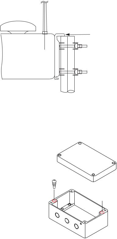
1.3 Junction Box
Mount the junction box where the junction box is protected from rain and water splash.
Mounting
1.Open the lid of the junction box and fix the junction box with four tapping screws (5x20). Avoid bundling the 3.3 m cable of the junction box together with any power cable. This causes malfunction.
2.Connect cables to the terminal board, referring to Chapter 2 and 3.
3.Fix the lid after connecting external equipment.
4.Clamp the cable with several U-type cable clamps (local supply) at suitable intervals.
Clamp the cable with
U-type cable clamps.
Fixing holes |
Cable entry |
|
|
(5x20 tapping screws) |
|
Cable clamp
10
1.4 Power Supply (option)
The length of the power cable between the power supply and the transponder unit is 3.5 m. Keep this length in mind when selecting a mounting location. A longer cable should not be used – voltage drop will result, affecting performance.
When selecting a mounting location for the unit, keep the following in mind:
•Keep the unit out away from areas subject to water splash.
•Locate the unit away from exhaust pipes and vents.
•The mounting location should be well ventilated.
•Mount the unit where shock and vibration are minimal.
•A magnetic compass will be affected if the unit is placed too close to it. Observe the following compass safe distances to prevent disturbance to the magnetic compass:
Steering compass: 0.6 m
Standard compass: 0.9 m
Fix the unit with four tapping screws (4x16) to a desktop or the deck as shown in the figure below. It is not necessary to open the cover.
1.5 Pilot Plug (option)
The pilot plug should be mounted near where the pilot steers the ship. This plug is used to connect a PC to display AIS information for use by the pilot. Refer to the outline drawing at the back of this manual for mounting dimensions.
11
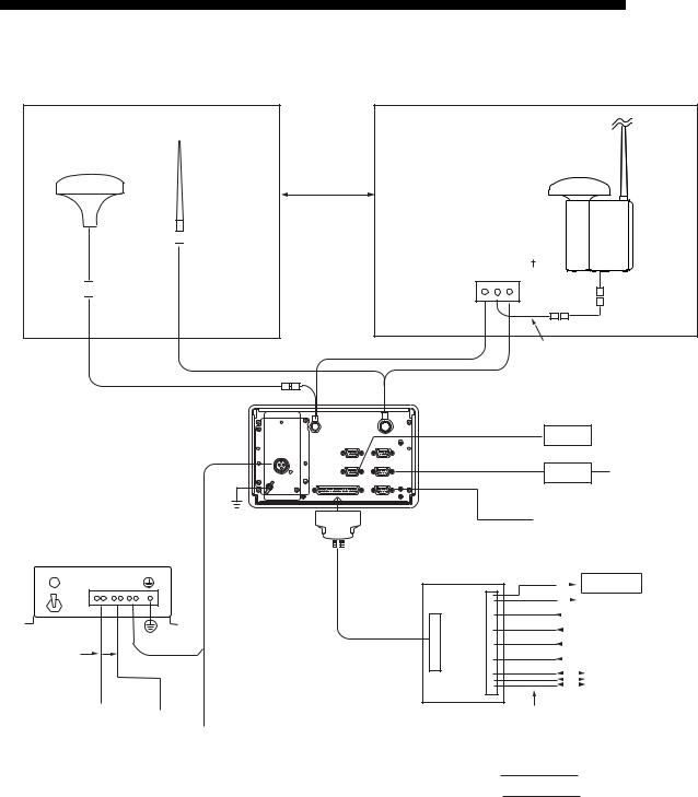
2. WIRING
Connect the equipment, referring to the interconnection diagram at the back this manual.
GPS Antenna GPA-017S
GSC-001 150M-W2VN
0.6 m

 ***
***
RG-10/UY
8D-FB-CV, 30 m/50 m: Option RG-10/UY: Local supply
Power Supply |
|
(3.5 m) * |
|
035 |
|
PR-240-CE |
|
|
|
|
- |
AC DC DC |
A3SPF0013- |
|
IN IN |
OUT |
|
DPYC-1.5** |
1.5 sq |
MJ |
|
||
Ship’s mains
GPS/VHF Conbined
Antenna GVA-100
Either one
GPS ANT VHF ANT
AUX-1 AUX-2
LAN AD-10 IN
EXTRA I/O
Distributor unit |
|
0.9 m |
DB-1 |
|
|
|
*** |
|
|
*** |
|
|
|
|
|
RG-10/UY |
|

 Attached to Distributor (approx. 1m)
 : ground is not required.
LAN cable
(category 4 or higher)
PC
TTYCS-1Q** AD-100 Gyrocompass
|
Transponder |
AIS sentence out |
||||||||
|
unit |
(4800 bps) |
||||||||
|
||||||||||
|
FA-100 |
|
|
|
|
|
|
|
|
Pilot Plug |
|
|
|
|
|
|
|
|
|
||
|
|
|
|
|
|
|
|
|
|
|
|
|
|
|
|
|
|
|
|
|
|
|
|
|
|
|
|
|
|
|
|
Alarm out |
|
|
|
|
|
|
|||||
|
|
|
|
|
|
|
|
|
|
GPS receiver |
|
|
|
|
|
|
|
||||
|
|
|
|
|
|
|
|
|
|
Heading sensor |
|
|
|
|
|
|
|
|
|||
Approx. 3.3 m |
|
|
|
|
|
|
|
|
Speed sensor or ROT |
|
|
|
|
|
|
|
|||||
|
|
|
|
|
|
|
|
Beacon receiver |
||
|
|
|
|
|
|
|
|
|
|
|
|
|
|
|
|
|
|
|
|
|
AIS data In/Out |
|
|
|
|
|
|
|
|
|
||
|
|
|
|
|
|
|
|
|
|
|
100-115/200-230 VAC |
24 VDC |
Junction Box |
TTYCS-1Q** or TTYCS-4** |
|
1φ, 50/60 Hz |
12-24 VDC |
CB-100 |
|
|
|
|
|
||
|
(Connect to the alternative |
|
|
: Standard |
|
|
|
||
power source.)
: Option
: Local Supply *: If the ship’s mains is 12 VDC, cable length should be less than 50 cm.
EXTRA IO port: Outputs AIS sentence (4800 bps).
AUX-1, AUX-2 port: Not used.
12
Loading...