


OPERATOR'S MANUAL
NAVIGATIONAL ECHO SOUNDER
Model
FE-800
www.furuno.com

IMPORTANT NOTICES
General
•This manual has been authored with simplified grammar, to meet the needs of international users.
•The operator of this equipment must read and follow the descriptions in this manual. Wrong operation or maintenance can cancel the warranty or cause injury.
•Do not copy any part of this manual without written permission from FURUNO.
•If this manual is lost or worn, contact your dealer about replacement.
•The contents of this manual and equipment specifications can change without notice.
•The example screens (or illustrations) shown in this manual can be different from the screens you see on your display. The screens you see depend on your system configuration and equipment settings.
•Save this manual for future reference.
•Any modification of the equipment (including software) by persons not authorized by FURUNO will cancel the warranty.
•All brand and product names are trademarks, registered trademarks or service marks of their respective holders.
How to discard this product
Discard this product according to local regulations for the disposal of industrial waste. For disposal in the USA, see the homepage of the Electronics Industries Alliance (http://www.eiae.org/) for the correct method of disposal.
How to discard a used battery
Some FURUNO products have a battery(ies). To see if your product has a battery, see the chapter on Maintenance. Follow the instructions below if a battery is used. Tape the + and - terminals of battery before disposal to prevent fire, heat generation caused by short circuit.
In the European Union
The crossed-out trash can symbol indicates that all types of batteries |
|
|
must not be discarded in standard trash, or at a trash site. Take the |
|
|
used batteries to a battery collection site according to your national |
Cd |
|
legislation and the Batteries Directive 2006/66/EU. |
||
|
In the USA
The Mobius loop symbol (three chasing arrows) indicates that Ni-Cd and lead-acid rechargeable batteries must be recycled. Take the used
batteries to a battery collection site according to local laws.
Ni-Cd Pb
In the other countries
There are no international standards for the battery recycle symbol. The number of symbols can increase when the other countries make their own recycle symbols in the future.
i
SAFETY INSTRUCTIONS
The operator must read the safety instructions before attempting to operate the equipment.
|
WARNING |
could result in death or serious injury. |
|
|
|
|
Indicates a potentially hazardous situation which, if not avoided, |
|
|
|
|
|
|
|
|
CAUTION |
Indicates a potentially hazardous situation which, if not avoided, |
|
|
|
could result in minor or moderate injury. |
|
|
|
|
|
|
|
|
|
Warning, Caution |
Prohibitive Action |
Mandatory Action |
|
|
|
|
|
|
 WARNING
Do not open the equipment.
The equipment uses high voltage that can cause electrical shock. Refer any repair work to a qualified technician.
If water leaks into the equipment or something is dropped into the equipment, immediately turn off the power at the switchboard.
Fire or electrical shock can result.
If the equipment is giving off smoke or fire, immediately turn off the power at
the switchboard.
WARNING
Fire or electrical shock can result.
If you feel the equipment is acting abnormally or giving off strange noises, immediately turn off the power at the switchboard and contact a FURUNO service technician.
 WARNING
Do not disassemble or modify the equipment.
Fire, electrical shock or serious injury can result.
Make sure no rain or water splash leaks into the equipment.
Fire or electrical shock can result if water leaks into the equipment.
Do not place liquid-filled containers on or near the equipment.
Fire or electrical shock can result if a liquid spillsWARNINGinto the equipment.
Do not operate the equipment with wet hands.
Electrical shock can result.
Use the proper fuse.
Use of the wrong fuse can cause fire or electrical shock.
ii
 CAUTION
Handle the LCD carefully.
The LCD is made of glass, which can cause injury if broken.
Do not transmit with the transducer out of water.
Damage to the transducer can result.
Properly adjust the gain.
Too little gain gives no picture. Too much gain shows excessive noise on the picture. Using the depth data for navigation when the gain is incorrectly set can lead to a dangerous situation.
Too high |
Correct |
Too low |
The data presented by this equipment is intended as a source of navigation information.
The prudent navigator never relies exclusively on any one source of navigation information, for safety of vessel and crew.
The use of two transceivers with the same frequency will result in interference.
When fitting more than one transceiver, ensure the frequencies are different.
Warning Label(s)
Warning label(s) is(are) attached to the equipment. Do not remove the label(s). If a label is missing or damaged, contact a FURUNO agent or dealer about replacement.
SAFETY INSTRUCTIONS
 CAUTION
Observe the following compass safe distances to prevent magentic compass deviation:
|
Standard |
Steering |
|
|
Compass |
Compass |
|
Display Unit |
0.75 m |
0.50 m |
|
FE-8010 |
|||
|
|
||
|
|
|
|
Transceiver Unit |
1.50 m |
0.95 m |
|
FE-8020 |
|||
|
|
||
|
|
|
|
Matching Box |
0.80 m |
0.50 m |
|
MB-502 |
|||
|
|
||
|
|
|
|
Matching Box |
0.65 m |
0.40 m |
|
MB-504 |
|||
|
|
||
|
|
|
About the TFT LCD
The TFT LCD is constructed using the latest LCD techniques and uses 99.99% of its pixels. The remaining 0.01% may drop out or blink, however this is not an indication of malfunction.
 WARNING
To avoid electrical shock, do not remove cover. No user-serviceable parts inside.
Name: |
Warning Label 1 |
Type: |
86-003-1011-3 |
Code No.: |
100-236-233 |
iii

TABLE OF CONTENTS
FOREWORD ........................................ |
v |
||
SYSTEM CONFIGURATION .............. |
vi |
||
1. OPERATION ................................. |
1 |
||
1.1 |
Controls....................................... |
1 |
|
1.2 |
How to Turn the Power On/Off.... |
2 |
|
1.3 |
Panel and Key Brilliance ............. |
3 |
|
1.3.1 |
Day/Night Mode ................... |
3 |
|
1.4 |
Display Modes and Screen |
|
|
|
Indications ................................... |
4 |
|
1.4.1 |
NAV Mode ........................... |
5 |
|
1.4.2 |
HISTORY Mode................... |
6 |
|
1.4.3 |
OS DATA Mode ................... |
7 |
|
1.5 |
Menu Overview ........................... |
8 |
|
1.6 |
How to Select a Range ............... |
9 |
|
1.6.1 How to enable/disable auto |
|||
|
|
range.................................... |
9 |
1.7 |
Gain............................................. |
9 |
|
1.7.1 How to adjust the gain ......... |
9 |
||
1.7.2 |
Automatic Operation .......... |
10 |
|
1.7.3 How to offset the auto |
|
||
|
|
gain .................................... |
10 |
1.8 |
Clutter........................................ |
11 |
|
1.9 |
Interference ............................... |
11 |
|
1.10 |
PICT Advance ........................... |
12 |
|
1.11 |
How to Set the Depth Alarm...... |
12 |
|
1.12 |
How to Use the Function Key.... |
13 |
|
1.13 |
How to Output to External |
|
|
|
Equipment ................................. |
13 |
|
1.14 |
How to Choose a Transceiver... |
14 |
|
1.15 |
How to Set the Depth Below |
|
|
|
Surface (DBS) ........................... |
14 |
|
1.16 |
How to Set Draught................... |
15 |
|
1.17 |
Logbook .................................... |
15 |
|
1.18 |
How to Change the Unit of |
|
|
|
Measurement ............................ |
17 |
|
1.19 |
How to Select the Displayed |
|
|
|
Course....................................... |
17 |
|
1.20 |
How to Change the Colour |
|
|
|
Scheme ..................................... |
17 |
|
2.5 |
How to Set Bottom Link RNG ... |
21 |
|
2.6 |
How to Set the Speed of |
|
|
|
Sound........................................ |
21 |
|
2.7 |
Alert Menu................................. |
22 |
|
2.7.1 |
Active alert list ................... |
22 |
|
2.7.2 How to display the alert |
|
||
|
|
log...................................... |
23 |
2.7.3 |
Bottom lost......................... |
24 |
|
2.7.4 |
GPS lost ............................ |
24 |
|
2.8 |
Alarms, Warnings and |
|
|
|
Cautions.................................... |
25 |
|
2.8.1 Alert icons and their |
|
||
|
|
meanings ........................... |
26 |
2.9 |
How to Set or Adjust the Time .. |
27 |
|
2.9.1 |
External time...................... |
27 |
|
2.9.2 |
Internal time....................... |
28 |
|
2.10 |
Key Beeps................................. |
28 |
|
2.11 |
System Information ................... |
29 |
|
2.12 |
User Reset ................................ |
29 |
|
3.MAINTENANCE AND
TROUBLESHOOTING................. |
30 |
|
3.1 |
Checklist ................................... |
30 |
3.2 |
Cleaning the Display Unit.......... |
30 |
3.3 |
Transducer Maintenance .......... |
30 |
3.4 |
Replacing the Fuse/Battery....... |
31 |
3.5 |
Troubleshooting ........................ |
31 |
3.6 |
Fan and LCD Backlight Life |
|
|
Expectancy ............................... |
31 |
MENU TREE.................................. |
AP-1 |
|
PARTS LOCATIONS..................... |
AP-3 |
|
LIST OF TERMS AND |
|
|
ABBREVIATIONS ......................... |
AP-4 |
|
SPECIFICATIONS.......................... |
SP-1 |
|
INDEX |
.............................................. |
IN-1 |
2. SYSTEM MENU .......................... |
18 |
|
2.1 |
How to Set the Basic Range |
|
|
Scale ......................................... |
18 |
2.2 |
How to Set Transducer |
|
|
Parameters................................ |
19 |
2.2.1 |
Bottom level ....................... |
19 |
|
2.2.2 |
TVG level ........................... |
20 |
|
2.2.3 |
Echo offset......................... |
20 |
|
2.3 |
How to Set TX Rate .................. |
20 |
|
2.4 |
How to Set Bottom Tail |
|
|
|
Display ...................................... |
21 |
|
iv

FOREWORD
A Word to FE-800 Owners
Thank you for purchasing this navigational echo sounder. We are confident you will discover why FURUNO has become synonymous with quality and reliability.
Since 1948, FURUNO Electric Company has enjoyed an enviable reputation for innovative and dependable marine electronics equipment.
This dedication to excellence is furthered by our extensive global network of agents and dealers.
Please carefully read and follow the safety information and operating and maintenance instructions set forth in this manual before attempting to operate the equipment and conduct any maintenance. Your navigational echo sounder will perform to the utmost of its ability only if it is operated and maintained in accordance with the correct procedures.
This equipment is designed, produced and documented by FURUNO ELECTRIC CO., LTD., complying with ISO 9001 standards as certified by the Lloyd’s Register of Quality Assurance System.
Features
The FE-800 is a color navigation echo sounder which operates with 50 or 200 kHz frequency. The FE-800 is comprised of a control unit, transceiver, matching box and transducer. Echoes are output on an 8.4-inch LCD screen.
The main features of the FE-800 are:
•Complies with the following regulations:
ISO9875:2000, IEC60945 Ed.4, IEC61162-1 Ed.4, IEC61162-1 450, IEC62288 Ed.2.
•Can display dual frequency (50 kHz/200 Khz) depth reading on one screen.
•Three display modes available:
•NAV mode: Standard display showing depth readings.
•OS DATA mode: Shows own ship location, time, COG/SOG alongside current depth readings.
•HISTORY mode: Shows past readings in graph form alongside current depth readings.
•Can be connected to an external monitor (RD-20/RD-50) for remote display of readings.
•Compatible with Bridge Alert Management systems - IMO MSC.302(87)
•Can connect up to two transceivers, allowing dual on-screen display of echoes.
•Connecting the optional printer allows printing of echo data.
•Can save/replay up to 24 hours of depth reading history.
•Connecting a PC with the optional data recording software allows recording of echo data.
Program numbers
Unit |
Program Number |
FE-8010 |
1251002-01.xx |
FE-8020 |
1251003-01.xx |
“xx” indicates minor version numbers.
v

SYSTEM CONFIGURATION
Printer
PP-505-FE
Signal
TRANSCEIVER UNIT
FE-8020
Contact signal
BAM
Network Equipment |
LAN |
or PC |
|
Ship’s MAIN |
|
100-230 VAC |
|
JUNCTION
BOX
JIS F8821-1MO
O-20A3P
MATCHING BOX
MB-502
TRANSDUCER  50B-6B
Equipment category
Display unit |
Protected from the weather |
|
|
Transceiver unit |
Protected from the weather |
|
|
DISPLAY UNIT
FE-8010
Power
Power
RD-20 or RD-50

 RD-20 or RD-50

 Navigator

 BAM or IF-2503
JUNCTION
BOX
JIS F8821-1MO
O-20A3P
MATCHING BOX
MB-504
TRANSDUCER
200B-8B
vi

1.OPERATION
1.1Controls
All operations of the FE-800 are carried out with the controls on the front panel of the display unit. Some functions require a long key press, while others require a short key press.
DRAUGHT |
DRAUGHT |
MENUESC Display the Main Menu.
ALARM |
RNG |
DISP |
MENU |
ACK |
+ |
|
ESC |
FUNC |
RNG |
◄ |
► |
|
- |
|
ENT |
Removing the cover
While pressing the center with your thumbs as illustrated, pull the cover towards you to remove it.
▲
BRILL
▼
Key |
Function |
||
|
|
Press to turn the FE-800 on/off. |
|
|
|
||
|
|
|
|
ALARM/ |
Turns off alert buzzer. |
||
ACK |
|||
|
|||
FUNC |
Long press to memorize menu functions. Short press to recall memorized |
||
|
|
functions. |
|
RNG |
Increases depth range. |
||
+ |
|||
|
|||
RNG |
Decreases depth range. |
||
- |
|||
|
|||
DISP |
• Cycles through display modes in the following order: |
||
|
|
(Nav → History → OS Data → Nav) |
|
|
|
• Returns to Main display from any location in the menus. |
|
MENU/ ESC |
• Displays/closes the menu. |
||
|
|
• Returns one level in the menu tree (unless on first level). |
|
W• Adjusts key brilliance.
• Menu screens - Moves up/down levels in the menu tree.
and |
• History - Moves the cursor location in the history mini-window. |
|
• Logbook - Changes the displayed page. |
X |
• Mini-windows (GAIN, etc.) - Switches settings (EG: FORE/AFT settings). |
ENT |
|
S |
• Opens [Brilliance Setting] pop-up window/Adjust panel brilliance. |
BRILL |
• Select menu items in menu window. |
T• Change settings in current pop-up window.
1
1. OPERATION
1.2How to Turn the Power On/Off
Note 1: Make sure the unit is connected correctly to each transceiver.
Note 2: After turning the unit off, wait at least 5 seconds before you turn the power on again.
Press the  button to turn the unit on. With the power on, press the
  button again to turn the unit off.
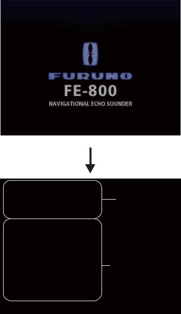
On startup, the unit displays a splash screen for approximately ten seconds, then begins a self-test. The self-test checks the logic circuits, battery status and displays the program version currently in use.
Splash screen
Unit Name |
: FE-8010 |
Serial No |
: XXXXXX |
Program No |
: 1251002-01.xx |
ROM |
: OK |
RAM |
: OK |
Unit Name |
: FE-8020 |
Display unit’s self-test results
Serial No |
: XXXXXX |
Program No |
: 1251003-01.xx |
ROM |
: OK |
RAM |
: OK |
Unit Name |
: FE-8020 |
Serial No |
: XXXXXX |
Program No |
: 1251003-01.xx |
ROM |
: OK |
RAM |
: OK |
Press any Key to continue.
Transceiver test results. NOTE: Only connected transceivers are tested. Transceiver test results appear after approximately ten seconds.
Self-test results
After the self-test completes, the mode used before the FE-800 was turned off is activated. You can now change modes freely (See section 1.4.)
Note: If any errors occur during the self-test process, the self-test stops the startup procedure. Contact your local Furuno dealer for service.
2
1. OPERATION
1.3Panel and Key Brilliance
Both panel and key brilliance can be adjusted from the main screen using the following procedure:
1. Press S or T on the BRILL pad to open the Brilliance pop-up window.
2.Press S or T to adjust panel brilliance.
3.Press W or X to adjust key brilliance.
4.Press the MENU/ESC key to close the pop-up window. Brilliance settings for Day or Night mode are stored separately.
When changing modes, the last-used setting is restored.
1.3.1Day/Night Mode
The FE-800 has Day and Night display settings to allow better screen visibility. To switch between modes, do the following:
1.Press the MENU/ESC key to open the Main menu.
2.Select [Day/Night], then press the ENT key.
3.Select [Day] or [Night] as appropriate, then press the ENT key.
4.Press the MENU/ESC key once to close the menu.
The default settings for Day and Night modes are shown in the table below.
Mode |
Panel |
Key |
|
Brilliance |
Brilliance |
||
|
|||
Day |
9 |
2 |
|
Night |
2 |
2 |
3
1. OPERATION
1.4Display Modes and Screen Indications
The FE-800 has 3 main display modes: NAV, HISTORY, OS DATA.
The display modes are set in a cycle pattern, and each press of the DISP key changes the selected mode, in the sequence shown below.
NAV  HISTORY
  OS DATA
Note 1: OS DATA mode requires external EPFS data (EG:GPS). If [Time Adjust] in the [Service] menu is set to [Internal] when initial settings are made, the OS DATA screen is
unavailable. To change the [Time Adjust] settings, consult a FURUNO technician.
Note 2: The main display shows output from both transducers if two are connected. If only one is connected, the display shows only the output from the connected transducer. The menu display may change slightly for single transducer configurations.
For brevity, this manual uses a two transducer output display for all explanations.
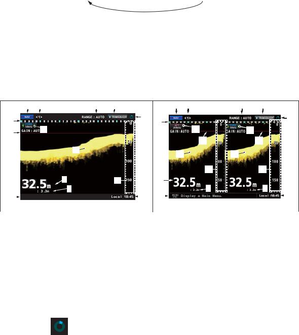
An example of the difference between single and dual frequency displays and their respective marks and indications is shown below.
13
DRAUGHT |
DRAUGHT |
8 |
|
|
|
|
|
|
|
|
|
|
|
|
|
|
|
|
|
|
|
|
|
|
|
|
|
|
|
|
|
|
|
|
|
|
|
|
|
|
|
|
|
|
|
|
|
|
|
|
|
|
|
|
|
|
|
|
|
|
|
|
No. |
|
|
|
Name |
|
|
|
|
|
|
Description |
||||||||
1 |
|
Mode indicator |
Shows current display mode |
||||||||||||||||
|
|
|
|
|
|
|
(NAV, NAV + HISTORY or NAV + OS DATA). |
||||||||||||
2 |
|
Transceiver no. |
Shows the currently selected transceiver. |
||||||||||||||||
3 |
|
Range setting |
Shows the currently selected range setting. |
||||||||||||||||
4 |
|
Reading indicator |
Shows the currently selected reference point for depth readings. |
||||||||||||||||
|
|
|
|
|
|
|
(TRANSDUCER, KEEL OR SURFACE.) |
||||||||||||
5 |
|
Time scale |
Shows the time scale for displayed readings. One square is equal to 1 |
||||||||||||||||
|
|
|
|
|
|
|
minute of readings. The distance from one blue square to the next is equal |
||||||||||||
|
|
|
|
|
|
|
to ten minutes of readings. |
||||||||||||
6 |
|
System |
|
|
Shows unit is functioning normally. Stops moving when unit is |
||||||||||||||
|
|
||||||||||||||||||
|
|
status |
|
|
malfunctioning. |
||||||||||||||
|
|
indicator |
|
|
|
|
|
|
|
|
|
|
|
|
|
|
|
||
|
|
|
|
|
|
|
|
|
|
|
|
|
|
|
|
||||
7 |
|
Depth |
Shows current depth and selected depth unit. |
||||||||||||||||
8 |
|
Draught setting |
Shows the draught setting for respective transducer. |
||||||||||||||||
9 |
|
Alarm message |
Shows active alarms or a brief description of the selected menu item. |
||||||||||||||||
|
|
or |
Note: Alarm messages take priority over menu descriptions. |
||||||||||||||||
|
|
menu description |
|
|
|
|
|
|
|
|
|
|
|
|
|
||||
10 |
|
Transducer |
Shows the location of the transducer and output signal. |
||||||||||||||||
11 |
|
Sounding echo |
Shows the reflected echo. |
||||||||||||||||
12 |
|
Range indicator |
Shows depth range. Changes with range scale. |
||||||||||||||||
13 |
|
Depth Alarm line |
Indicates the depth setting for the depth alarm. |
||||||||||||||||
14 |
|
Time |
Indicates time and time setting (UTC, Local, etc.) |
||||||||||||||||
4
1. OPERATION
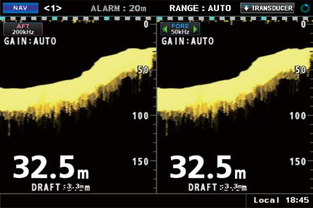
1.4.1NAV Mode
This is the default mode for the FE-800. The screen shows depth and echo from FORE and AFT positions.
The default display order of the echo readings is AFT - FORE.
|
|
|
|
|
|
|
|
|
|
|
|
|
|
|
|
|
|
|
|
|
|
|
|
|
|
|
|
|
|
|
|
|
|
|
|
|
|
|
|
|
|
|
|
|
|
|
|
|
|
|
DRAUGHT |
|
|
|
DRAUGHT |
|
|||
MENUESC Display the Main Menu.
5
1. OPERATION
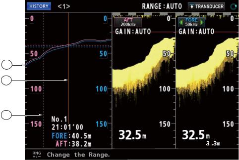
1.4.2HISTORY Mode
This mode provides a mix of Contour and Strata echo readings taken. The amount of data stored in the HISTORY log depends on the interval setting. The table below shows the differences in amount of data that can be stored.
Interval setting |
Amount of data stored |
2 min |
24 hours |
1 min |
12 hours |
5 sec |
1 hour |
Previous echo readings can be accessed by using W or X to move the cursor.
1
2
3
DRAUGHT 


 DRAUGHT
Number |
Description |
1 |
FORE/AFT depth history. |
2 |
Time (location) in sounding depth history. Move this indicator using W or X. |
|
FORE/AFT history readings are displayed at the bottom of this screen. |
3 |
Change indicator. This line appears in the case of any de-synchronization |
|
between the FE-800 and connected sensors or units. |
6
1. OPERATION
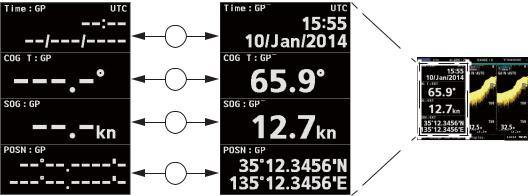
1.4.3OS DATA Mode
This mode shows Own Ship Data (OS DATA), and is only available if the [Time Adjust] setting in the [Service Menu] is set to [External].
To change the [Time Adjust] settings in the [Service Menu], consult a FURUNO technician.
1
2
3
DRAUGHT |
DRAUGHT |
4
The OS DATA mode requires a connected EPFS device, such as GPS. If there is no device connected, or connection is interrupted, the OS DATA is displayed as shown in the above left figure. The left side of the display shows the OS DATA, the right side of the display shows the current echo readings.
Number |
Description |
1 |
Date and Time as received by the EPFS device. |
2 |
COG (Course Over the Ground) as calculated by the EPFS device. |
3 |
SOG (Speed Over the Ground) as calculated by the EPFS device. |
4 |
POSN (Position) as calculated by the EPFS device. |
EPFS devices are often referred to as “talkers”. Below is a list of talker types, and their respective display names, which can be used with the FE-800.
Displayed talker name |
Description |
DE |
Decca Navigator |
GA |
Galileo positioning system |
GL |
GLONASS positioning system |
GN |
Global navigation satellite system (GNSS) |
GP |
Global positioning system (GPS) |
II |
Integrated instrumentation |
IN |
Integrated navigation |
LA |
Loran A |
LC |
Loran C |
7
1. OPERATION
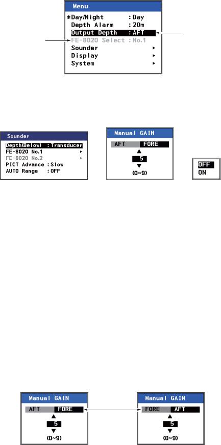
1.5Menu Overview
1. Press the MENU/ESC key to open the Main menu.
Selected item Unselectable is highlighted. items are grey.
2.Use the S or T key to navigate the menu. The item currently selected is highlighted.
3.To choose a menu item, press the X ENT key.
Depending on which item is selected, a new menu, a setting window or a setting box is displayed.
Newly opened menu |
Settings window |
Settings box |
4.Use the S or T key to navigate the menu or adjust settings as required.
5.Press the X ENT key to open the selected item, or to apply the setting changes.
To return to the previous menu, or to abandon changes, press W or the MENU/ESC key. 6. Press the DISP key once, or press the MENU/ESC key several times to close the menus.
Note 1: If [FE-8020 No.2] is not enabled in the [Service Menu], the following menu items are grey and not selectable:
•Main menu → [FE-8020 Select]
•[Sounder] menu → [FE-8020 No.2]
•[System] menu → [Parameters] → [FE-8020 No.2]
•[System] menu → [Information] → [FE-8020 No.2]
To enable [FE-8020 No.2], consult a FURUNO technician.
Note 2: For brevity, all further references to the X ENT key are written as “ENT key”.
If the display settings are set to FORE - AFT at installation, some pop-up menu layouts will change according to the FORE - AFT or AFT - FORE display order.
The example below shows both the default, AFT - FORE, and the custom display order of FORE - AFT.
Reversed
Default |
Custom |
For the sake of brevity, all explanations and images in this manual use the default.
8
 Loading...