


 Loading...
MARINE RADAR
MODEL FR-2165DS

c |
|
|
|
Y o u r L o c a l A g e n t / D e a l e r |
|
|
|
|
9 - 5 2 , A s h i h a r a - c h o , |
|
|
N i s h i n o m i y a , J a p a n |
|
|
T e l e p h o n e : 0 7 9 8 - 6 5 - 2 1 1 1 |
|
|
T e l e f a x : |
0 7 9 8 - 6 5 - 4 2 0 0 |
|
|
|
|
F I R S T E D I T I O N : N O V 1 9 9 8
A l l r i g h t s r e s e r v e d . Printed in Japan |
B |
: J U L . 1 3 , 1 9 9 9 |
P U B . N o . I M E - 3 4 6 8 0 - B |
|
|
( D A M I ) |
F R - 2 1 6 5 D S |
 SAFETY INSTRUCTIONS
 WARNING
Radio Frequency Radiation
Hazard
The radar scanner emits electromagnetic radio frequency (RF) energy which can be harmful, particularly to your eyes. Never look directly into the scanner aperture from a close distance while the radar is in operation or expose yourself to the transmitting scanner at a close distance.
Distances at which RF radiation levels of 100 and 10 W/m2 exist are given in the table below.
Note: If the scanner unit is installed at a close distance in front of the wheelhouse, your administration may require halt of transmission within a certain sector of scanner revolution. This is possible Ask your FURUNO representative or dealer to provide this feature.
Model |
Radiator |
Distance to |
Distance to |
|
type |
100W/m2 |
10W/m2 |
||
|
point |
point |
||
|
|
|||
FR-2165DS |
SN4A |
— |
1.2 m |
|
|
|
|
||
SN5A |
— |
1.0 m |
||
|
||||
|
|
|
|
 WARNING
|
Do not open the equipment |
|
|
unless totally familiar with |
|
|
electrical circuits and |
|
|
service manual. |
|
ELECTRICAL |
Only qualified personnel |
|
should work inside the |
||
SHOCK |
||
HAZARD |
equipment. |
|
|
|
|
|
Wear a safety belt and hard |
|
|
hat when working on the |
|
|
scanner unit. |
Serious injury or death can result if someone falls from the radar scanner mast.
Construct a suitable service platform from which to install the scanner unit.
Serious injury or death can result if someone falls from the radar scanner mast.
Turn off the power at the mains switchboard before beginning the installation.
Fire, electrical shock or serious injury can result if the power is left on or is applied while the equipment is being installed.
Do not install the display unit where it may get wet from rain or water splash.
Water in the display unit can result in fire, electrical shock or equipment damage.
i

 WARNING
Be sure that the power supply is compatible with the voltage rating of the equipment.
Connection of an incorrect power supply can cause fire or equipment damage. The voltage rating of the equipment appears on the label above the power connector.
Use only the specified power cable.
Fire or equipment damage can result if a different cable is used.
 CAUTION
Ground the equipment to prevent electrical shock and mutual interference.
Observe the following compass safe distances to prevent deviation of a magnetic compass:
|
Standard |
Steering |
|
|
compass |
compass |
|
|
|
|
|
Display |
1.70 m |
0.90 m |
|
Unit |
|||
|
|
||
|
|
|
|
Scanner |
2.15 m |
1.60 m |
|
Unit |
|||
|
|
||
|
|
|
|
Power |
|
|
|
supply |
0.50 m |
0.30 m |
|
unit |
|||
|
|
||
PSU-004 |
|
|
|
|
|
|
|
Power |
|
|
|
supply |
1.20 m |
0.90 m |
|
unit |
|||
|
|
||
PSU-001 |
|
|
|
|
|
|
ii
TABLE OF CONTENTS
EQUIPMENT LISTS ............................................................................ |
iv |
SYSTEM CONFIGURATION ............................................................... |
vi |
MOUNTING
1.1 |
Scanner Unit ............................................................................................................. |
1-1 |
1.2 |
Display Unit ............................................................................................................... |
1-7 |
1.3 |
Power Supply Units ................................................................................................. |
1-15 |
WIRING
2.1 |
Scanner Unit ............................................................................................................. |
2-1 |
2.2 |
Display Unit ............................................................................................................... |
2-5 |
2.3 |
Changing AC Power Specification of Display Unit .................................................. |
2-10 |
2.4 |
Power Supply Units .................................................................................................. |
2-11 |
2.5 |
Installation and Connection of Rectifier Unit ........................................................... |
2-13 |
INITIALIZATION AND ADJUSTMENT
3.1 |
Tuning Initialization .................................................................................................... |
3-1 |
3.2 |
Accessing Menus for Initialization and Adjustment ................................................... |
3-1 |
3.3 |
Adjusting Video Signal Level ..................................................................................... |
3-1 |
3.4 |
Heading Alignment .................................................................................................... |
3-2 |
3.5 |
Adjusting Sweep Timing ............................................................................................ |
3-3 |
3.6 |
Suppressing Main Bang ............................................................................................ |
3-3 |
3.7 |
Confirming Magnetron Heater Voltage ...................................................................... |
3-4 |
3.8 |
Initial Setting Menus .................................................................................................. |
3-6 |
INSTALLATION OF OPTIONAL EQUIPMENT
4.1 |
Gyro Converter GC-8 ................................................................................................ |
4-1 |
4.2 |
ARP Board ARP-26 ................................................................................................... |
4-7 |
4.3 |
RP Board RP-26...................................................................................................... |
4-10 |
4.4 |
Performance Monitor PM-30 ................................................................................... |
4-14 |
4.5 |
Alarm Kit .................................................................................................................. |
4-15 |
PACKING LISTS........................................................................................................ |
A-1 |
OUTLINE DRAWINGS ............................................................................................ |
D-1 |
INTERCONNECTION DIAGRAM ...................................................................... |
S-1 |
SCHEMATIC DIAGRAMS ..................................................................................... |
S-2 |
iii
EQUIPMENT LISTS
Standard Supply
Name |
Type |
Code No. |
Qty |
Remarks |
|
|
|
|
|
|
|
|
SN4A-RSB-0051-N-3 |
– |
|
24 rpm, 2500 mm, no deicer |
|
|
|
|
|
|
|
Scanner Unit |
SN4A-RSB-0051-I-3 |
– |
Select |
24 rpm, 2500 mm, w/deicer |
|
SN5A-RSB-0051-N-3 |
– |
one |
24 rpm, 2700 mm, no deicer |
|
|
|
|
||||
|
|
|
|||
|
|
|
|
|
|
|
SN5A-RSB-0051-I-3 |
– |
|
24 rpm, 2700 mm, w/deicer |
|
|
|
|
|
|
|
Display Unit |
RDP-124 |
– |
1 |
|
|
|
|
|
|
|
|
|
PSU-001-60 |
– |
|
100 VAC |
|
Power Supply |
|
|
Select |
|
|
|
|
|
|
||
Unit for |
PSU-001-61 |
– |
110 VAC |
|
|
Scanner Unit |
|
|
one |
|
|
PSU-001-62 |
– |
|
115 VAC |
|
|
|
|
|
|||
|
|
|
|
|
|
Power Supply |
PSU-004-2-50-S |
– |
1 |
|
|
Unit |
|
|
|||
|
|
|
|
|
|
|
|
|
|
|
|
Spare Parts |
SP03-12800 |
000-087-692 |
1 |
For DC power |
|
|
|
|
|
|
|
|
|
|
|
CP03-14601, CP03-19103, |
|
|
CP03-19900 |
000-089-393 |
|
CP03-13916, CP03-13907, |
S |
|
|
|
|
Signal Cable S03-84-15 (15 m) |
E |
|
|
|
|
|
E |
|
|
|
|
CP03-14601, CP03-19103, |
|
|
|
|
|
|
|
|
CP03-19910 |
000-089-394 |
|
CP03-13916, CP03-13907, |
P |
Installation |
|
|
Select |
Signal Cable S03-84-20 (20 m) |
|
|
|
A |
|||
Materials* |
|
|
one |
CP03-14601, CP03-19103, |
|
|
|
C |
|||
|
CP03-19920 |
000-089-395 |
|
CP03-13916, CP03-13907, |
K |
|
|
|
|
Signal Cable S03-84-30 (30 m) |
I |
|
|
|
|
CP03-14601, CP03-19103, |
N |
|
CP03-19930 |
000-089-396 |
|
CP03-13916, CP03-13907, |
G |
|
|
|
|
Signal Cable S03-84-60 (60 m) |
L |
|
|
|
|
|
|
|
|
|
|
FP03-06201, FP03-06502, |
|
|
FP03-06510 |
000-089-400 |
|
I |
|
|
|
FP03-06503 |
|||
|
|
|
|
S |
|
Accessories |
|
|
1 |
|
|
|
|
For console: FP03-06201, |
T |
||
|
FP03-06550 |
000-089-476 |
|
FP03-06502, FP03-06503, |
S |
|
|
|
|
FP03-06504 |
|
|
|
|
|
|
|
* CP03-14601: For scanner unit, CP03-19103: For display unit, CP03-13916: For power supply unit PSU-004, CP03-13907: For power supply unit PSU-001
iv
Optional Equipment
Name |
Type |
Code No. |
Qty |
Remarks |
|
|
|
|
|
|
|
Rectifier |
RU-3423 |
000-030-443 |
1 |
AC → 24 VDC |
|
|
|
|
|
|
|
Slave Display |
FMD-8010 |
- |
1 |
|
|
|
|
|
|
|
|
Gyro Converter |
GC-8-2 |
008-446-520 |
1 set |
Separate shipment |
|
|
|
|
|
|
|
Interswitch |
RJ-7 |
- |
1 |
|
|
|
|
|
|
|
|
Interswitch |
RJ-8 |
- |
1 |
|
|
|
|
|
|
|
|
Performance Monitor |
PM-50 |
- |
1 |
|
|
|
|
|
|
|
|
|
RU-1758 |
000-030-416 |
1 |
220 V → 100 V, for |
|
|
display unit |
||||
|
|
|
|
||
|
|
|
|
|
|
|
RU-1803 |
000-030-420 |
1 |
440 V → 100 V, for |
|
Transformer Unit |
display unit |
||||
|
|
|
|||
|
|
|
|
||
RU-6522 |
000-030-410 |
1 |
220 V → 200 V, for |
||
|
|||||
|
scanner unit |
||||
|
|
|
|
||
|
|
|
|
|
|
|
RU-3305 |
000-030-448 |
1 |
For deicer |
|
|
|
|
|
|
|
PM Installation Kit |
OP03-150 |
008-485-490 |
1 set |
|
|
|
|
|
|
|
|
ARPA |
ARP-26 |
008-485-500 |
1 set |
|
|
|
|
|
|
|
|
|
RP-26-T |
008-485-510 |
|
For tabletop, console |
|
|
|
type display unit |
|||
Video Plotter |
|
|
1 set |
||
|
|
|
|||
RP-26-Z |
008-485-520 |
For separate type control |
|||
|
|
||||
|
|
head |
|||
|
|
|
|
||
|
|
|
|
|
|
Separate Control Head |
OP03-151 |
008-485-530 |
1 |
|
|
Mounting Kit |
|
||||
|
|
|
|
||
|
|
|
|
|
|
Alarm Kit |
OP03-156 |
008-500-650 |
1 |
|
|
|
|
|
|
|
v
SYSTEM CONFIGURATION
POWER SUPPLY UNIT
PSU-001
For 220/230 VAC RU-1758 only
POWER SUPPLY
UNIT PSU-004
24 VDC |
|
For |
DISPLAYFor |
|
|||
100/110/ |
RU-3423 |
UNITSCANNER |
|
|
|
||
115/220/230 VAC, |
|
|
|
1φ, 50/60Hz |
|
|
|
|
OPTION |
|
UNIT |
SHIP’S MAINS
100/110/115/ 220/230 VAC 1φ, 50/60 Hz
SCANNER UNIT
RSB-0051
DISPLAY UNIT
RDP-124
|
IEC 61162-1Input/Output |
Navigator |
|
|
|
IEC 61162-1Input |
|
|
|
Speed Log |
|
|
|
|
|
|
ARPA Board |
Slave Display |
|
|
ARP-26 |
|
|
|
FMD-8010 |
|
|
|
Video Plotter |
|
|
|
|
|
|
|
RP-26 |
|
|
|
Gyro Converter |
Performance |
|
|
GC-8 |
|
|
|
|
Monitor |
|
|
|
PM-50 |
|
|
|
Gyrocompass |
|
For DE-ICER |
|
|
|
RU-1803 |
RU-3305 |
|
|
440 VAC |
|
110/115/220 VAC |
|
1φ, 50/60 Hz |
|
1φ, 50/60 Hz |
|
|
100 VAC |
|
|
|
1φ, 50/60 Hz |
|
|
vi
MOUNTING
1.1 Scanner Unit
Mounting considerations
•The scanner unit is generally installed either on top of the wheelhouse or on the radar mast, on a suitable platform. Locate the scanner unit where there is a good all-round view.
•No funnel, mast or derrick should be within the vertical beamwidth of the scanner in the bow direction, especially zero degrees ±5°, to prevent blind sectors and false echoes on the radar picture.
•It is rarely possible to place the scanner unit where a completely clear view in all directions is available. Thus, you should determine the angular width and relative bearing of any shadow sectors for their influence on the radar at the first opportunity after fitting.
•Locate the antenna of a direction finder clear of the scanner unit to prevent interference to the direction finder. A separation of more than two meters is recommended.
•To lessen the chance of picking up electrical interference, avoid where possible routing the signal cable near other onboard electrical equipment. Also avoid running the cable in parallel with power cables.
•A magnetic compass will be affected if placed too close to the scanner unit.
Observe the following compass safe distances to prevent deviation of a magnetic compass: Standard compass, 2.15 m, Steering compass, 1.60 m.
•Do not paint the radiator aperture, to ensure proper emission of the radar waves.
•The signal cable run between the scanner and the display is available in lengths of 15 m (standard), 20 m, 30 m and 60 m. Whatever length is used it must be unbroken; namely, no splicing allowed.
•Deposits and fumes from a funnel or other exhaust vent can adversely affect
the aerial performance and hot gases may distort the radiator portion. The scanner unit must not be mounted where the temperature is more than 70°C.
•The scanner base is made of cast aluminum. To prevent electrolytic corrosion of the scanner base, use the seal washers and corrosion-proof rubber mat and ground the unit with the ground wire (supplied).
•Leave sufficient space around the unit for maintenance and servicing. See the scanner unit outline drawing for recommended maintenance space.
1-1
Installation precaution for S-band scanner unit
If an S-band scanner unit is mounted near the end of a platform to provide sufficient rotation clearance for the radiator, the scanner unit, because of its weight, swings up and down by ship’s vibration and rolling, exerting excessive levels of stress at the base of the radiator, which can damage the radiator. To prevent this, relocate the scanner unit, or if relocation is not possible, reinforce the platform.
Pole for DF, etc.
Remarkable vibration (pitching)
Mounting position
EXAMPLE
Pole for DF
Mount the scanner unit Directly on the mast or on the platform, as near as possible to the center of the mast.
Figure 1-1 Mounting of S-band scanner unit
1-2
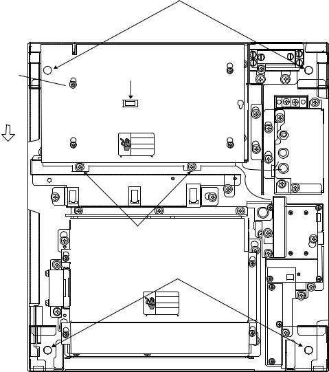
Scanner unit assembling
The scanner radiator and the scanner housing are shipped in separate packages and must be assembled at installation. Assemble them as below.
The scanner unit may be assembled before hoisting it to the mounting platform. However, do not lift the scanner unit by the radiator.
1.Remove two protective caps from the radiator flange and rotary joint flange.
2.Grease an O-ring and place it in the groove of the rotary joint flange. Make sure the O-ring is not pinched during assembling.
3.Secure the feeder waveguide to the rotary joint flange with four M6x16 hex bolts.
4.Fix the feeder waveguide on the radiator bracket with a waveguide clamp, a clamp insulator, two flat washers, and two M6x50 hex bolts.
5.Grease other O-ring and set it in the groove of the radiator flange.
6.Set the scanner radiator to the bracket and fix it temporarily with eight M10x20 hex bolts, spring washers and flat washers.
7.Fasten the feeder waveguide to the radiator flange with four M6x16 hex bolls.
8.Fasten the scanner radiator to the bracket with eight M10x20 bolts.
1-3

Scanner radiator
Hex bolt M6x16
|
|
O-ring |
|
|
Rotary joint flange |
|
|
Hex bolt M10x20 |
|
O-ring |
|
Radiator flange |
|
Spring washer M10 |
|
|
|
Waveguide flange |
Radiator bracket |
Flat washer M10 |
|
||
|
|
|
Feeder waveguide |
|
Hex bolt M6x50 |
Hex bolt M6x16 |
|
Flat washer M6 |
|
|
|
|
|
Waveguide clamp |
|
|
Clamp insulator |
Note 1: Coat bolts, nuts, washers and waveguide flanges outside O-ring grooves to prevent electrolytic corrosion. (Do not allow silicone sealant to touch O-ring and O-ring grooves.)
Apply silicone sealant here.
O-ring
O-ring
Waveguide
Radiator Apply silicone sealant here. flange flange
Note 2: Do not pinch O-ring and keep it clean.
Note 3: Use grease on scanner covers and O-rings. Do not use silicone sealant.
Figure 1-2 Scanner unit assembling
1-4
Mounting the scanner unit
1.Referring to the scanner outline drawing, drill four bolt holes (15 mm dia.) in the radar mast platform or the deck.
2.Place the corrosion-proof rubber mat (supplied) on the mounting platform.
3.Using the two L-angle metal plates on the scanner top, lift the scanner base with the antenna radiator and place the scanner unit on the rubber mat. Orient the scanner so its cable glands face the ship’s stern.
Feeder waveguide
Note 2
L-angle metal plate
Note 1
Place the rope around scanner radiator (feeder waveguide side) to prevent scanner from rotating when lifting
the scanner base.
Note 1: Take care not to damage scanner exterior by the rope.
Note 2: Tensile load should not be applied to scanner radiator.
Figure 1-3 How to lift the scanner unit
4.Fix the scanner base to the mounting platform with four M12x60 hex bolts, nuts, washers and seal washers (supplied).
5.Arrange the grounding terminal at the nearest grounding spot with the M6x25 hex bolt, nut and washers (supplied). Then, fix a ground wire (RW-4747, 320 mm long) to the terminal.
6.Connect the other end of the ground wire to the ground terminal of the scanner unit.
7.Coat grounding terminal and fixing bolts on the scanner unit with silicone sealant (supplied).
1-5
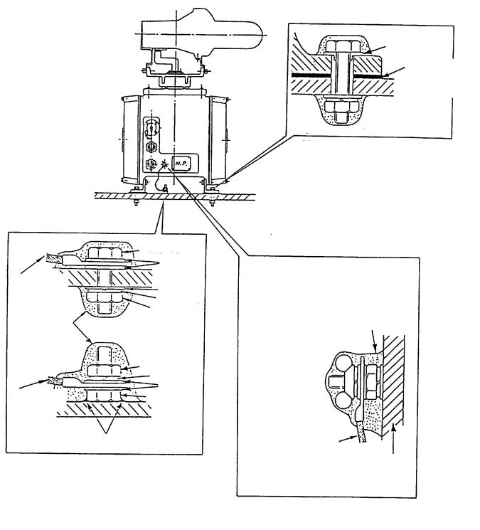
ANT MOTOR SW 
Hex bolt
FW
Ground
wire FW SW
Hex nut
Hex nut
SW FW
Ground Hex bolt wire
Welding
Arrange ground terminal at nearest grounding spot.
Seal washer
Corrosion proof rubber mat
Set seal washer and corrosion-proof rubber mat, and apply silicone sealant.
Coat with silicone sealant after attaching ground wire.
Ground wire
Scanner body
Ground terminal is fitted to
the scanner body at the factory.
Figure 1-4 Mounting of scanner unit
1-6
1.2 Display Unit
Before mounting the display unit
If Gyro Converter GC-8 (option) is to be used, install and setup the GYRO CON-
VERTER Board before mounting the display unit, because of the difficulty involved in doing it after the display unit is installed. Instructions for installation and setup are in Chapter 4.
Mounting considerations
When selecting a mounting location, keep in mind the following points:
•Select a location where the display unit can be viewed and operated conveniently and where the screen can be viewed while facing towards the bow.
•Locate the unit out of direct sunlight and away from heat sources because of heat that can build up inside the cabinet.
•Locate the equipment away from places subject to water splash and rain.
•The display unit is very heavy. Be sure the mounting location is strong enough to support the weight of the unit under the continued vibration which is normally experienced on the ship. If necessary reinforce the mounting location.
•Determine the mounting location considering the length of the signal cable between the scanner unit and the display unit and the power supply cable between the display unit and the Power Supply Unit PSU-004.
•Leave sufficient space on the sides and rear of the unit to facilitate maintenance. Also, leave a foot or so of “service loop” in cables behind the unit so it can be pulled forward for servicing or easy removal of connectors.
•A magnetic compass will be affected if placed too close to the display unit. Observe the following compass safe distances to prevent deviation of a magnetic compass: Standard compass, 1.70 m, Steering compass, 0.90 m.
Mounting procedure
Tabletop mounting
This procedure requires two people to complete.
1.Make four holes of 12 mm diameter in the mounting location referring to the outline drawing at the end of this manual.
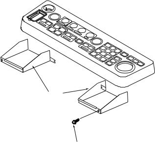
2.Unfasten the screws fixing the right and left brackets on the control panel.
3.Unfasten bolts (four total) in the brackets.
Left, right arm cover
M4x10
Figure 1-5 Control head
1-7
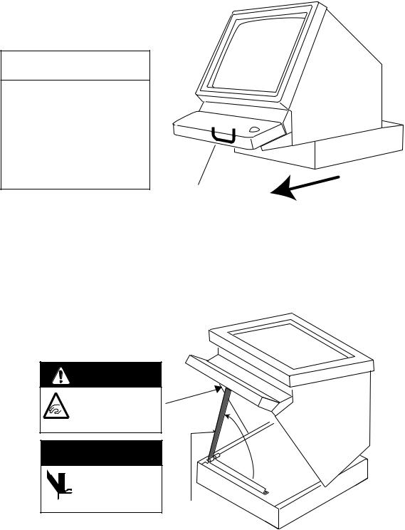
4.While one person is holding the mounting base at the sides, pull the handle on the underside of the control head to draw the display unit toward you until you hear a click.
 CAUTION
Use two people to complete this step.
The display unit may fall to the deck when it is pulled forward, since the mounting base is not yet fastened to the mounting location.
Handle |
Pull forward |
|
Figure 1-6 Display unit
5.This step requires two people to complete. While raising the monitor until the CRT is horizontal, fix the stay as follows:
a)Raise the stay as shown below.
Two warning labels on the underside of monitor
HORIZONTAL
WARNING
Possibility of injury. Hold handle when mounting display unit.

 WARNING
Display unit may fall.
 Lock stay before
servicing.
Stay
Figure 1-7 Display unit, inside view
1-8
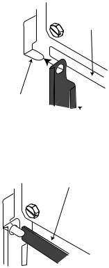
b) While pushing the stopper, set the catch on the display unit in the hole at the front edge of the stay.
Stopper
Catch
 Stay
Stay
Figure 1-8 Setting catch to hole in stay
c) Release hand from stopper.
Release stopper; fix stay.
Figure 1-9 Stay fixed
6.Fasten the display unit to the mounting location at front fixing holes (2 points) with M10 bolts, nuts and flat washers, using the pipe box spanner (supplied).
You cannot fasten the display unit at the rear fixing holes while the monitor is raised.
7.Retract the stay and lower the monitor.
8.Fasten the display unit to the mounting locations at rear fixing holes (2 points) with M10 bolts, nuts and flat washers, using the pipe box spanner (supplied).
The rear left hole is hid under the PTU cover. Remove the cover as follows:
(1)Unfasten five M3x8 screws at the top of the PTU cover and two M4x8 screws at the front of the cover to slide the cover toward the front side.
(2)Remove the cover by grasping the knob on the top of the cover.
1-9
*M3x8, 5 pcs.
Slide forward.
Fixing hole (rear)
Knob |
* |
* 

* |
* |
M4x8, 2 pcs. |
Fixing hole (front) |
Figure 1-10 How to remove the PTU cover
9. Push the monitor forward until you hear a click.
10.Fix the brackets with the M10 bolts removed at step 3.
Console type mounting
1.Make six holes of 15 mm diameter and a cable entrance hole through the deck referring to the outline drawing at end of this manual.
2.Open the front cover.
3.Fix the equipment with M12 bolts, nuts and washers.
4.Hoist the console to the deck by using the eye bolts attached to the console. Remove the eye bolts and set the cosmetic caps to the eye bolt holes.
Separating the control head
The control head connects to the display unit with a connection cable, thus it can be located where desired, using the separate control head kit (option). Follow the procedure on the next page to separate the control head from the display unit.
1-10
Separate type control head kit (Type: OP03-151, No.: 008-485-530)
Name |
Type |
Qty |
Code No. |
Remarks |
|
|
|
|
|
|
|
Cable Assy. |
UL246SB20P/1P |
1 |
000-140-812 |
10 m, 03S9422 |
|
|
|
|
|
|
|
Nonslip Rubber |
A-1042-C-4505 |
4 |
000-800-986 |
w/tape |
|
Feet |
|||||
|
|
|
|
||
|
|
|
|
|
|
Monitor Front |
03-144-1361 |
1 |
100-263-340 |
|
|
Cover |
|
||||
|
|
|
|
||
|
|
|
|
|
|
KB Fixing Plate |
03-144-1691 |
1 |
100-263-940 |
|
|
|
|
|
|
|
|
Handle Plate |
03-144-1632 |
1 |
100-268-040 |
|
|
|
|
|
|
|
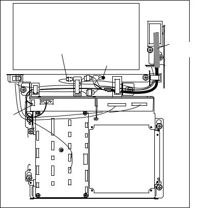
Display unit modification procedure
1.Raise the monitor unit referring to procedure for tabletop mounting on page 1-
7.
2.Unplug two connectors from the control head cable (P412 from MOTHER Board and J583) and unfasten two earth wires.
PTU COVER |
|
J583 |
Control Head |
Cable |
|
Earth Wire |
|
J418 |
|
MB 03P9251 |
|
P412 |
|
INT |
|
03P9252 |
|
Figure 1-11 Display unit, inside view
3.Lower the monitor.
4.Unfasten the M4 screw fixing the ground terminal of the connection cable.
5.Push the monitor forward until you hear a click.
6.Unscrew four screws fixing the top cover of the display unit.
1-11
7.Remove three clamps fixing the connection cable in the monitor unit.
8.Unfasten four screws fixing the right and left brackets on the control head.
9.Unfasten four screws fixing the right and left covers of the display unit. 10.Unfasten six screws fixing the right and left KB arms.
11.Unfasten three screws fixing the panel cover.
KB arm (L) 03-144-1341
M5x25 SUS 3 pcs.
Panel cover |
KB arm (R) |
|
03-144-1345 |
||
03-144-1342 |
||
|
||
M4x10, 3 pcs. |
|
M5x25 SUS 3 pcs.
Control head |
M5x25 SUS 4 pcs. |
|
Figure 1-12 Detaching the control head
Control head modification procedure
1.Unfasten eight screws (M4X8) on the underside of the control head. Unplug connectors P314, P312 and P317 from the control head. Separate the KB bottom plate from the control head.
2.Unfasten the screw (M4) fixing the ground terminal and two screws (M4X8) fixing the clamp. Remove the connection cable assy.
3.Unfasten two screws (M6X12) from the inside of the bottom plate of the control head to dismount the handle.
1-12
4.Replace the cable assy. with cable assy. UL2464SB2-0P/1P (10 m, supplied) as below and reassemble the control head.
P312 FX Connector
KB |
BOTTOM |
|
|
PLATE |
|
Upset Screw
M6X12 (2 pcs.)
KB Clamp
Handle
KB Fixing Plate
Screw
M4X8 (8 pcs.)
|
|
J317 |
|
Lay cable in slot. |
J314 |
(underside) |
|
||
|
|
|||
J312 |
|
|
|
|
|
(underside) |
|
||
|
|
|
||
|
(underside) |
|
||
Earth Wire
P314 XH3P
Replace with |
Spacer Pan-head Screw M4X8 (2 pcs.) |
cable assy. in |
Be careful not to pinch cable between |
kit. |
KB clamp and spacer. |
|
Figure 1-13 Control head |
Connection of display unit to control head
1.Attach the handle to the handle plate, using the screws for the handle and bottom cover of the control head.
2.Attach the handle plate to location where the KB arms were fastened.
3.Pull the monitor toward you until you hear click.
4.Lead in the cable assy. (option) from the rear entrance of the display unit. See Chapter 2.
5.Raise the monitor and fix the stay.
6.Inside the display unit, fasten ground wire of the cable assembly with an M4 screw on the chassis.
1-13
7.Plug in two connectors of connection cable (P412, J583: See illustration on the previous page.)
8.Lower the monitor.
9.Attach the monitor front cover (option) to the place the panel cover have been, using the screw for the panel cover.
10.Attach rubber to feet to the bottom of the keyboard if the keyboard is not going to be permanently fixed. To fix the keyboard to a desired location, fasten the KB fixing plate to the keyboard and desired location with two upset screws (M5X25, formerly used to fasten KB arms) and two tapping screws (φ6.5, local supply) as below.
KB Fixing Plate
CONTROL HEAD |
φ6.5 |
|
SIDE VIEW |
||
Tapping |
||
|
||
|
Screw |
|
KB Fixing |
M5X25 |
|
Plate |
||
CONTROL HEAD TOP VIEW |
Upset |
|
|
Screw |
Figure 1-14 How to attach KB fixing plate
11.Set dust cover KB (supplied) on the control head.
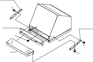
Attachment of hood
1.Set two spacers (supplied) to the lower two of the four M5 holes in the CRT panel.
2.Screw two screws (supplied) into the holes in the hood.
3.Set the bottom of the hood to the screws at the bottom of the CRT panel, and then fasten the two screws at the top of the hood to the CRT panel.
1-14
1.3 Power Supply Units
The Power Supply Unit PSU-001 (for scanner unit) and PSU-004 (for display unit) do not contain usual operating controls. Therefore, they can be installed in any recessed place either in vertical or horizontal position. (For the console mount display unit, the PSU-004 can be installed inside the console.) However, select a dry and well-ventilated location and observe the compass safe distances below to prevent deviation of a magnetic compass.
|
Standard |
Steering |
|
|
compass |
compass |
|
|
|
|
|
PSU-001 |
1.20 m |
0.90 m |
|
(for scanner unit) |
|||
|
|
||
|
|
|
|
PSU-004 |
0.50 m |
0.30 m |
|
(for display unit) |
|||
|
|
||
|
|
|
1-15
WIRING
2.1 Scanner Unit
Two signal cables are terminated at the scanner unit: signal cable S03-84 and signal cable 660V-MPYCY-16 from the Power Supply Unit PSU-004.
Preparations
Open the port side cover (six bolts) of the scanner unit. Unfasten fixing plates to acess terminal boards.
Signal cable S03-84
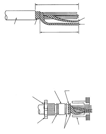
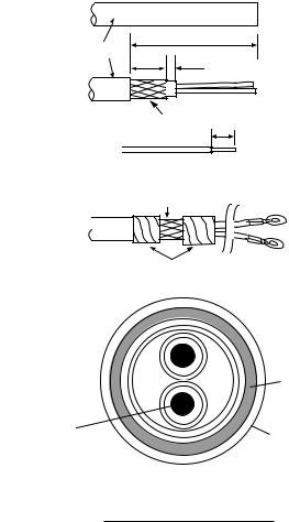
1.Shorten the cable, extending the length actually required by 600 mm. Strip off about 600 mm of the anti-corrosive vinyl sheath, and 590 mm of the armor and the inner vinyl sheath being careful not to nick the braided shield.
|
|
Approx. 550 mm |
|
|
|
|
|
|
|
|
Inner shield |
Anti-corrosive |
Armor |
|
|
|
Outer shield |
|
|
|
|
||
vinyl sheath |
|
|
|
|
|
|
|
|
|
|
|
|
|
|
Approx. 540 mm |
|
|
Figure 2-1 Fabricating the signal cable S03-84
2.Turn off the ANT MOTOR SW on the scanner unit(Refer to Figure 1-4).
3.Unravel the outer shield with a screwdriver or similar tool to expose the cores beneath the outer shield.
4.Similar to step 2, expose the cores beneath the inner shield. Mark all cores for future identification.
5.Slide the clamping gland, washers and gasket onto the cable. (Use lower side gland.)
Gasket
Armor
Seal with putty after tightening.
Clamping gland |
|
|
|
|
|
|
|
||
Washer |
Gland body |
|||
|
||||
|
|
|
||
|
|
|
Washer |
|
Figure 2-2 Passing clamping gland, washers and gasket on signal cable
2-1
6.Ground the armor through the two washers as shown above. Trim the shields considering their location on the earth terminal inside the scanner unit. Fit a crimp-on lug (yellow, FV5.5-4, ø4) to inner and outer shields, then connect them to the ground terminal inside the scanner unit.
7.Determine the length of each core considering its location on STB-1 in the scanner unit (see the interconnection diagram on page S-1). Remove approx. 6 mm of the vinyl insulation from the end of each core and fix the crimp-on lug FV1.25-M3 (Red) to each core.
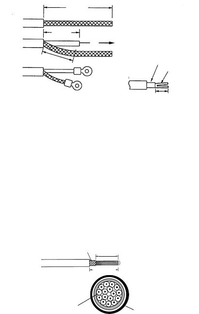
8.Remove the outer sheath of the coaxial cable (2C-2V) by 75 mm. Pull back the braided shield to expose the inner core. Remove approx. 25 mm of insulator from the end of inner core and fold back conductor as illustrated below. Shorten the shield leaving approx. 45 mm. Fit crimp-on lugs to the conductor (FVD1.25- 3, Red) and braided shield (FV1.25-M3, Red).
75 mm
Coaxial cable
2C-2V
50 mm
Fold back the conductor as illustrated below.
45 mm
Crimp-on lug FVD1.25-3  (Red, 3)
Crimp-on lug FV1.25-M3 (Red, 3)
Inner core
Conductor
6 mm
Figure 2-3 Fabrication of coaxial cable
9. Lead cable into cable gland, tighten clamping gland and seal with putty.
10.Connect wiring to terminal STB-1 in the scanner unit referring to the interconnection diagram.
Signal cable 660V-MPYCY-16 (JIS cable)
1.Unfasten the clamping gland from the upper cable gland, and remove the gasket and flat washers.
2.Shorten the cable as appropriate. Remove the vinyl sheath by 600 mm. Remove the armor by 590 mm.
Armor
590 mm
Conductors
600 mm
 Armor
Armor
Core
φ Vinyl sheath = 1.25 mm2
Figure 2-4 Fabrication of signal cable 660V-MPYCY-16
2-2
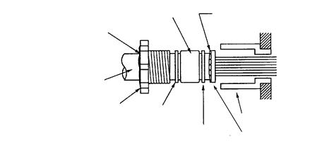
3.Slide the clamping gland, washers and gasket on the power cable. Fold back the armor by 5 mm, then put it between washer and cable gland body as below.
Gasket |
Armor (folded back) |
|
Seal with putty after tightening.
Vinyl sheath
Clamping gland
Flat |
|
|
Cable gland |
washer |
|
|
|
Flat |
|
|
|
|
|
Flat |
|
|
|
||
|
|
|
|
|
washer |
||
|
washer |
||
|
|
|
|
Figure 2-5 Passing clamping gland, washers and gasket on the signal cable
4.Determine the length of the cores considering their location on STB-2 and STB-
3. Trim conductors as necessary.
5.Ground the armor by inserting it through the two flat washers near the cable gland.
6.Remove the sheath of each core by 6 mm. Fix crimp-on lugs (FV1.25-4, blue, ø4) to each conductor. Make sure each connection is secure both electrically and mechanically.
7.Lead cable into cable gland, tighten clamping gland and seal with putty.
8.Connect the conductors to STB-2 and STB-3, referring to the interconnection diagram on page S-1.
9.Check for loose screws and poor contact on crimp-on lugs. Close terminal boards.
10.Grease the fixing bolts for the cover, gasket and tap holes in the scanner chassis. Attach cover.
When the de-icer is installed
1)Before beginning any work on the scanner unit, turn off the breaker for the deicer line at the main switchboard to remove the power (100 VAC, 1ø) to the deicer. (Turning off the power to the display unit has no effect.)
2)The neck of the scanner unit becomes VERY HOT when the de-icer is working. (The de-icer turns on when ambient temperature is below 0°C.)
2-3
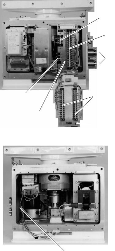
STB-2
STB-3
Cable
gland
Photo No. 2919
Cable clamp (3 pcs.) |
STB-1 |
TB fixing plate (1)
 TB fixing plate (2)
Figure 2-6 Scanner unit, port side view
Photo No. 2918
Ground terminal
Figure 2-7 Scanner unit, starboard side view, Tx chassis removed
2-4
2.2 Display Unit
Fabricating the power cable DPYCY-3.5 (JIS cable)
1.Remove the vinyl sheath by 80 mm.
2.Cut off jute tape wrapped around the armor.
3.Unravel the armor to expose the cores by about 35 mm.
4.Remove insulation of cores by about 10 mm. Fix crimp-on lugs to the cores and armor.
5.Cover the armor with vinyl tape, leaving the portion which will lie inside the cable clamp untaped.
(a) |
DPYCY-3.5 |
|
Vinyl sheath |
About 80 mm |
|
40 mm 5 mm |
||
|
||
(b) |
|
|
|
Armor 10 mm |
(c)
Lay this part in cable clamp.
(d)
Taping
|
|
Armor |
|
Core |
2 |
Vinyl |
|
S = 3.5 mm |
|||
|
sheath |
||
= 2.4 mm |
|
||
DPYCY-3.5 sectional view
Figure 2-8 Fabrication of power cable DPYCY-3.5 (JIS cable)
2-5
Loading...