


MARINE VHF RADIOTELEPHONE
FM-3000

FOREWORD
Congratulations on your choice of the FURUNO FM3000 Marine VHF Radiotelephone. We are confident that you will enjoy many years of trouble-free operation with this fine piece of equipment.
For more than 50 years FURUNO Electric Company has enjoyed an enviable reputation for quality and reliability throughout the world. This dedication is furthered by our extensive global network of agents and dealers.
Your equipment is designed and constructed to provide commercial grade performance and reliability, yet is affordable for pleasure craft owners.
Please carefully read this manual and follow the recommended procedure for installation, operation and maintenance. With proper care, your equipment should provide years of enjoyable and dependable communications.
Thank you for considering and purchasing FURUNO.
D FEATURES
Standard 4″×6″ flush mount design
Built-in DSC meets RTCM SC101 requirement
Rugged waterproof construction
NMEA Input/Output
Optional CONTROLLABLE MIC is connectable
IMPORTANT
READ ALL INSTRUCTIONS carefully and completely |
SAVE THIS INSTRUCTION MANUAL — This in- |
before using the transceiver. |
struction manual contains important operating instructions for |
|
the FM-3000. |
i
IN CASE OF EMERGENCY
If your vessel requires assistance, contact other vessels and the Coast Guard by sending a distress call on Ch 16.
USING CHANNEL 16
DISTRESS CALL PROCEDURE
1.“MAYDAY MAYDAY MAYDAY.”
2.“THIS IS ...............” (name of vessel)
3.Your call sign or other indication of the vessel (AND 9- digit DSC ID if you have one).
4.“LOCATED AT ...............” (your position)
5.The nature of the distress and assistance required.
6.Any other information which might facilitate the rescue.
Or, transmit your distress call using digital selective calling on Ch 70.
USING DIGITAL SELECTIVE CALLING (Ch 70)
DISTRESS CALL PROCEDURE
1.While lifting up the switch cover, push and hold [DISTRESS] for 5 sec. until you hear 5 short beeps change to one long beep.
2.Wait for an acknowledgment from a coast station.
• Channel 16 is automatically selected.
3.Push and hold [PTT], then transmit the appropriate information as at above.
NOTE
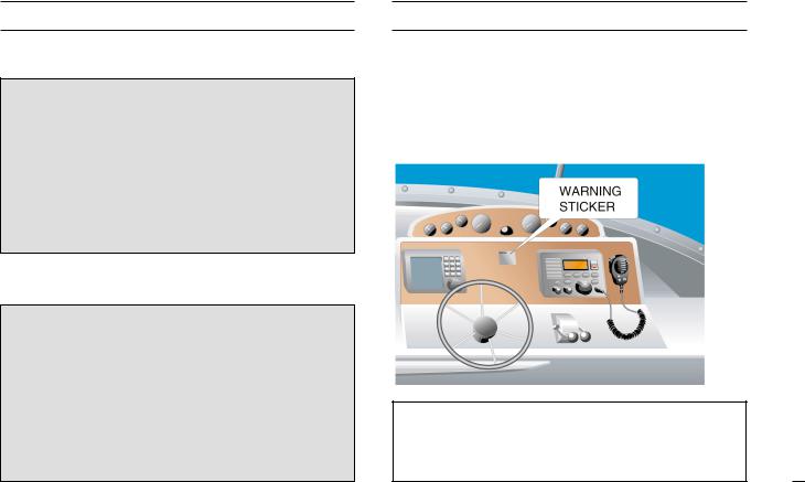
A WARNING STICKER is supplied with the transceiver.
To comply with FCC regulations, this sticker must be affixed in such a location as to be readily seen from the operating controls of the radio as in the diagram below. Make sure the chosen location is clean and dry before applying the sticker. (p. viii)
EXAMPLE
CLEAN THE TRANSCEIVER AND MICROPHONE THOROUGHLY WITH FRESH WATER after exposure to water including salt water, otherwise, the keys and switches may become inoperable due to salt crystallization.
ii

R SAFTY INSTRUCTION
For the operator
R CAUTION
Do not open the equipment.
Only qualified personal should work inside the equipment.
Do not disassemble or modify the equipment.
Fire, electrical shock or serious injury can result.
Turn off the power immediately if waterleaks into the equipment or the equipment is emmitting smoke or fire.
Continued use of the equipment can cause fire or electrical shock.
Any repair work must be done by a licensed radio technician.
Improper repair work can cause electrical shock or fire.
R CAUTION
The transceiver and optional FM-3010 employ waterproof construction, which corresponds to JIS waterproof specification, Grade 7 (1 m/30 min.). However, once the transceiver or microphone has been dropped, waterproofing cannot be guaranteed due to the fact that the case may be cracked, or the waterproof seal damaged, etc.
AVOID the use of chemical agents such as benzine or alcohol when cleaning, as they may damage the transceiver surfaces.
Distances at which radiation levels of 100 and 10 W/m2 exist are given in the table.
Distance to |
Distance to |
100 W/m2 point |
10 W/m2 point |
|
|
0.12 m |
0.39 m |
|
|
iii
|
For the installer |
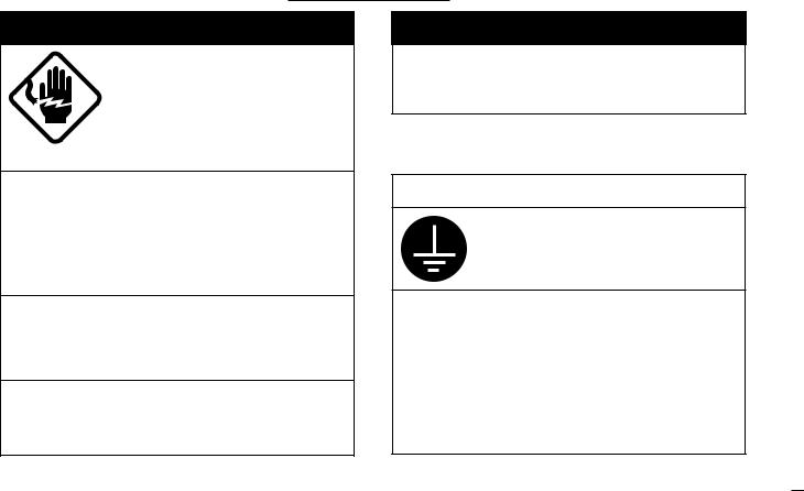
R WARNING |
R WARNING |
ELECTRICAL SHOCK HAZARD Do not open the equipment unless totally familiar with electrical circuits and service manual.
Only qualified personal should work inside the equipment.
Be sure that the power supply is compatible with the voltage rating of the equipment.
Connection of an incorrect power supply can cause fire or equipment damage. The voltage rating of the equipment appears on the label above the power connector.
Turn off the power at the switchboard before beginning the installation.
Fire or electrical shock can result if the power is left on.
DO NOT install the equipment where normal operation of the vessel may be hindered or where it could cause bodily injury.
DO NOT cut the DC power cable between the DC plug and fuse holder. If an incorrect connection is made after cutting, the equipment may be damaged.
R CAUTION
Ground the equipment to prevent electrical shock and mutual interference.
Observe the following compass safe distances to prevent interference to a magnetic compass:
|
Standard |
Steerling |
|
compass |
compass |
|
|
|
Transceiver |
0.95 m |
0.65 m |
|
|
|
iv

Table of Contents
FOREWORD ............................................................. |
i |
IMPORTANT .............................................................. |
i |
IN CASE OF EMERGENCY ..................................... |
ii |
NOTE ........................................................................ |
ii |
SAFTY INSTRUCTION ............................................ |
iii |
Table of Contents ..................................................... |
v |
System Configulation .............................................. |
vii |
Standard supply & Options .................................... |
viii |
1 Control ........................................................ |
1 |
|
1.1 |
Front Panel ................................................... |
1 |
1.2 |
Function Display ............................................ |
3 |
1.3 |
Microphone .................................................... |
4 |
2 Basic Operation ......................................... |
5 |
|
2.1 |
Channel Selection ......................................... |
5 |
2.2 |
Receiving and Transmitting ........................... |
7 |
2.3 |
Call Channel Programming ........................... |
8 |
Channel Comments ............................................ |
8 |
|
Optional Voice Scrambler Operation ................... |
9 |
|
3 |
Dualwatch/TRI-watch ............................... |
10 |
|
Description ........................................................ |
10 |
|
Operation .......................................................... |
10 |
4 |
Scan Operation ........................................ |
11 |
|
Scan Types ........................................................ |
11 |
|
Setting Tag Channels ........................................ |
12 |
|
Starting a Scan ................................................. |
12 |
5 DSC Operation ......................................... |
13 |
|
5.1 MMSI Code Programming ........................... |
13 |
|
5.2 |
DSC Individual ID ........................................ |
13 |
5.3 |
Position and Time Programming ................. |
15 |
5.4 |
Position/Time Indication .............................. |
16 |
5.5 |
Distress Call ................................................ |
17 |
5.6 Transmitting DSC Calls ............................... |
20 |
|
5.7 |
Receiving DSC Calls ................................... |
28 |
5.8 |
Received Messages .................................... |
31 |
5.9 DSC Set Mode ............................................ |
33 |
|
6 Other Functions ....................................... |
35 |
|
6.1 |
Intercom Operation ..................................... |
35 |
6.2 |
Microphone Lock Function .......................... |
36 |
6.3 |
Display Backlighting .................................... |
36 |
7 SET MODE ................................................ |
37 |
|
7.1 |
Set Mode Programming .............................. |
37 |
7.2 |
Set Mode Items ........................................... |
38 |
8 CONNECTIONS AND MAINTENANCE .... |
41 |
|
8.1 Antenna ....................................................... |
41 |
|
8.2 |
Fuse Replacement ...................................... |
41 |
8.3 |
Cleaning ...................................................... |
41 |
8.4 |
Connections ................................................ |
42 |
8.5 |
Mounting the Transceiver ............................ |
43 |
8.6 |
Optional Unit Installation ............................. |
45 |
8.7 |
Dimensions ................................................. |
46 |
v

9 TROUBLESHOOTING .............................. |
47 |
||
10 CHANNEL LIST ........................................ |
48 |
||
11 OPERATING RULES ................................ |
49 |
||
12 SPECIFICATIONS ..................................... |
50 |
||
13 FM-3010 CONTROLLABLE MIC ...................... |
51 |
||
13.1 |
Panel Description ...................................... |
51 |
|
13.2 |
Function Display ....................................... |
53 |
|
13.3 |
Channel Selection ..................................... |
55 |
|
13.4 |
Receiving and Transmitting ....................... |
56 |
|
13.5 |
Lock Functions .......................................... |
57 |
|
13.6 |
Display Backlighting .................................. |
57 |
|
13.7 |
Monitor Function ....................................... |
58 |
|
13.8 |
RF Attenuator Function ............................. |
58 |
|
13.9 |
Call Channel Programming ....................... |
58 |
|
13.10 |
Optional Voice Scrambler Operation ....... |
59 |
|
13.11 Dualwatch/Tri-watch Operation ............... |
59 |
||
13.12 |
Starting a Scan ....................................... |
60 |
|
13.13 |
Setting Tag Channels .............................. |
60 |
|
13.14 |
Set Mode Programming .......................... |
61 |
|
13.15 |
Intercom Operation ................................. |
62 |
|
13.16 |
Channel Comments ................................ |
62 |
|
13.17 |
FM-3010 Supplied Accessories .............. |
63 |
|
13.18 |
Installation ............................................... |
64 |
|
TEMPLATE
iv

System Configulation
13.8 V DC 
SPEAKER-MIC
CONTROLLABLE MIC
FM-3010 (OPTION)
Extension Cable (6 m)
FM-3020 (OPTION)
Connection Cable (6 m)
FM-3011 (with FM-3010)
VHF & CH70 RX ANT
|
-W2VN) |
TRANSCEIVER |
(150M |
|
|
FM-3000 |
|
PC or Navigation equipment
(White) |
NMEA0183 ver. 3.01 (DSC, DSE) |
|
(Red)
NMEA0183 ver. 2.0 or 3.01 (RMC, GGA, GNS, GLL)
(Black)
GPS Receiver
SPEAKER
Up to 2 FM-3020 are connectable. (Max. 18 m)
vii
Standard supply & Options
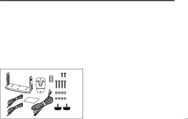
Standard supply
The following accessories are supplied: |
Qty. |
||
q Mounting bracket ............................................................ |
|
|
1 |
w Microphone hanger ......................................................... |
|
|
1 |
e Fuse (10 A) ..................................................................... |
|
|
2 |
r Mic hanger screws (3 × 16) ............................................ |
|
2 |
|
t Mounting screws (5 × 20) ............................................... |
|
4 |
|
y Flat washers (M5) ........................................................... |
|
|
4 |
u Spring washers (M5) |
...................................................... |
|
4 |
i Knob bolts for mounting bracket...................................... |
|
2 |
|
o DC power cable (FM-3003) ............................................ |
|
1 |
|
!0Warning sticker ............................................................... |
|
|
1 |
!1RCA connector cable Red .............................................. |
|
1 |
|
!2RCA connector cable White ........................................... |
|
1 |
|
q |
w |
e |
r |
|
|
|
t |
!1 |
!0 |
|
y |
|
u |
||
W |
|
|
|
ARNING |
|
|
|
Options
•FM-3010 CONTROLLABLE MIC (p. 51)
External microphone-type controller. Provides optional Intercom operation. 6 m (20 feet) microphone cable and mounting base included.
•FM-3020 MICROPHONE EXTENSION CABLE
6 m (20 feet) microphone extension cable for optional FM3010. Up to 2 FM-3020 can be connected. (18 m; 60 feet maximum)
•FM-3030 VOICE SCRAMBLER UNIT (pgs. 9, 40)
Ensures private communications. 32 codes are available. Not available in some countries.
•FM-3040 FLUSH MOUNT
For mounting the transceiver to a panel.
!2 |
o |
i |
vii

1. Controls
1.1 Front Panel
|
!1 |
!0 |
o |
i |
|
Function |
|
|
|
Speaker |
display |
|
|
|
VOL |
SQL |
q w e r t |
y |
u |
q[VOL] control (p. 7) Adjusts the audio level.
w[POWER] key
Toggles the transceiver power ON or OFF.
e[SQL] control (p. 7)
Sets the squelch threshold level.
r[HI/LO] key
Toggles power high or low when pushed. (p. 7)
•Some channels are set to low power only.
While pushing this key, some keys perform secondary functions.
t[CHANNEL] knob
Rotate [CHANNEL] to select the operating channels, Set mode settings, etc. (pgs. 7, 37)
While pushing [HI/LO], rotate [CHANNEL] to adjust the brightness of the LCD and key backlight. (p.36)
1
y[LO/DX] ( IC 
 SCR ) key
Toggles the Attenuator function ON or OFF when pushed momentarily. (p. 7)
•“LOCAL” appears when the Attenuator is in use. The order of indication precedence is “SP OFF,” “LOCAL” and “CALL.”
Activates an optional Intercom function when pushed for 1 sec. (p. 35)
Calls optional FM-3010 when pushed and held while in Intercom mode. (p. 35)
While pushing [HI/LO], activates an optional Voice scrambler function. (p. 9)
•The optional Voice scrambler function cannot be used on Channel 16 and 70.
u[16] ( 9 ) key
Selects Channel 16 when pushed. (p. 5)
Selects call channel when pushed for 1 sec. (p. 5)
•“CALL” appears when call channel is selected. “SP OFF” and “LOCAL” indications have priority.
Push for 3 sec. to enter call channel programming condition when call channel is selected. (p. 8)
While pushing [HI/LO], enters channel comments programming condition. (p. 8)
Enters Set mode when pushed while turning power ON. (p. 37)
1.Controls
i[DISTRESS] key
Transmits Distress call when pushed for 5 sec. (p. 17)
o[CH/WX] ( DW 
 U/I/C ) key
Selects and toggles the regular channels and weather channel when pushed momentarily. (p. 6)
While pushing [HI/LO], selects one of 3 regular channels in sequence when pushed. (p. 6)
•International, U.S.A. and Canadian channels are available for regular channels.
Starts Dualwatch or Tri-watch when pushed for 1 sec. (p. 10)
Stops Dualwatch or Tri-watch when either is activated.
!0[SCAN] ( TAG ) key (p. 12)
Starts and stops Normal or Priority scan when tag (scanned) channels are programmed.
Push [SCAN] ( TAG ) for 1 sec. to set or cancel the displayed channel as a tag (scanned) channel.
While pushing [HI/LO], push for 3 sec. to clear or set all tag channels.
!1[DSC/ENT] (POS ) key
Selects the DSC menu when pushed. (p. 13)
Shows current position and time from a GPS receiver, etc. when pushed for 1 sec. (p. 16)
2
1.Controls
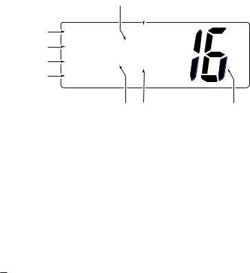
1.2 Function Display
|
o |
i |
|
q BUSY/TRANSMIT INDICATOR (p. 7) |
|
|
|
|
|
|
“BUSY” appears when receiving a signal or when the |
|
|
|
|
|
squelch opens. |
q |
BUSY |
INT |
|
||
|
“TX” appears while transmitting. |
||||
|
|
||||
w |
25W |
CALL |
|
w POWER INDICATOR (p. 7) |
|
e |
TAG SC |
DUP |
|
||
|
“25W” appears when high power is selected. |
||||
r |
CALLING |
|
|
|
|
|
|
|
“1W” appears when low power is selected. |
||
|
t y |
u |
e TAG CHANNEL INDICATOR (p. 12) |
||
|
|
||||
Appears when a tag channel is selected.
r CHANNEL COMMENT INDICATOR
Channel comment appears if programmed. (p. 8)
“Low Battery” blinks when the battery voltage drops to approx. 10 V DC or below.
“DUAL” appears during Dualwatch; “TRI” appears during Tri-watch. (p. 10)
t SCRAMBLER INDICATOR (p. 9)
Appears when an optional Voice scrambler is activated.
3
yDUPLEX INDICATOR (p. 6)
Appears when a duplex channel is selected.
• Duplex channel has a different TX and RX frequency.
uCHANNEL NUMBER READOUT
Indicates the selected operating channel number. “A” appears when a simplex channel is selected. “b” appears when a receive only channel for a Canadian channel group is selected. (p. 6)
In Set mode, indicates the selected condition. (p. 37)
iCHANNEL GROUP INDICATOR (p. 6)
Indicates whether an International “INT,” U.S.A. “USA,” Canadian “CAN” or weather “WEATHER” channel is selected.
oCALL CHANNEL INDICATOR
“CALL” appears when call channel is selected. (p. 5)
“SP OFF” appears when the internal speaker is turned OFF in Set mode. (p. 39)
“LOCAL” appears when the Attenuator is in use. (p. 7)
•The order of indication precedence is “SP OFF,” “LOCAL” and “CALL.”
1.Controls
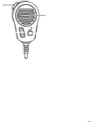
1.3 Microphone
q
Speaker
 Microphone w
 e
e
q[PTT] switch (p. 7)
Push and hold to transmit; release to receive.
wCHANNEL UP/DOWN KEYS [Y]/[Z] (pgs. 7, 37)
Push either key to change the operating channel, Set mode settings, etc.
e[16/9] key
Push to select Channel 16; push for 1 sec. to sselect call channel (default is Channel 9). (p. 5)
While pushing [16/9], turn power ON to toggle the Lock function ON or OFF. (p. 36)
4
2. Basic Operation
2.1 Channel Selection
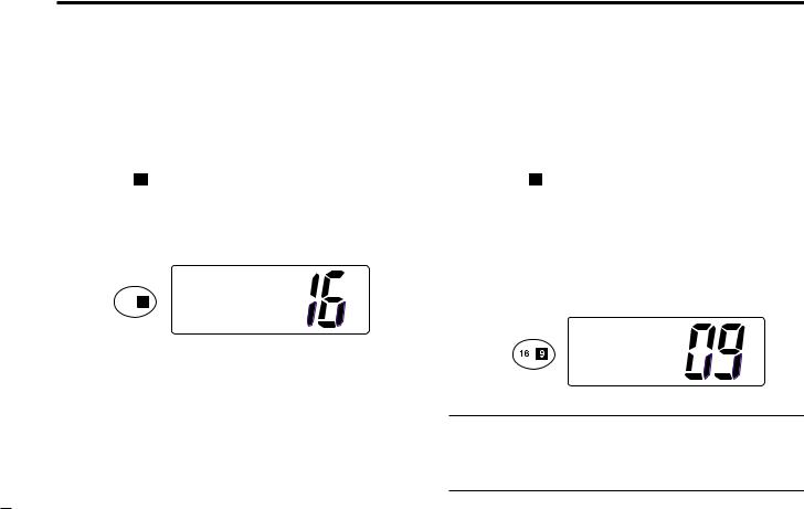
2.1.1 Channel 16
Channel 16 is the distress and safety channel. It is used for establishing initial contact with another station and for emergency communications. Channel 16 is monitored during both Dualwatch and Tri-watch. While standing by, you must monitor Channel 16.
Push [16] ( 9 ) momentarily to select Channel 16.
Push [CH/WX] to return to the condition before selecting Channel 16, or rotate [CHANNEL] to select operating channel.
INT
25W
Push 
 TAG CALLING
2.1.2 Channel 9 (Call channel)
Each regular channel group has a separate leisure-use call channel. Call channel is monitored during Tri-watch. Call channels can be programmed (p. 8) and are used to store your most often used channels in each channel group for quick recall.
Push [16] ( 9 ) for 1 sec. to select call channel of the selected channel group.
•“CALL” and call channel number appear.
•Each channel group may have an independent call channel after programming a call channel.
Push [CH/WX] to return to the condition before selecting call channel, or rotate [CHANNEL] to select an operating channel.
|
|
INT |
Push for |
25W |
CALL |
1 sec. |
TAG |
|
|
CALLING |
|
Convenient: Using microphone
Push [16/9] momentarily to select Channel 16.
Push [16/9] for 1 sec. to select call channel.
Push [Y]/[Z] to select any other operating channel.
5
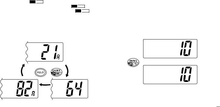
2.1.3 U.S.A., Canadian and International channels
There are 57 U.S.A., 61 Canadian and 57 International channels. These channel groups may be specified for the operating area.
q Push [CH/WX] ( DW 
 U/I/C ) to select a regular channel.
•If a weather channel appears, push [CH/WX] ( DW 
 U/I/C ) again. w While pushing [HI/LO], push [CH/WX] ( DW
 U/I/C ) to
change the channel group, if necessary.
•U.S.A., International (INT) and Canadian channels can be selected in sequence.
eRotate [CHANNEL] to select a channel.
•“DUP” appears for duplex channels.
•“A” appears for simplex channels.
USA
U.S.A. channels
Push |
+ |
CAN |
INT |
|
DUP |
Canadian channels |
International channels |
2.Basic Operation
2.1.4 Weather channels
There are 10 weather channels. Used for monitoring weather channels from the NOAA (National Oceanographic and Atmospheric Administration) broadcasts.
The transceiver can detect a Weather alert tone on the selected weather channel while receiving that channel, during standby on a regular channel or while scanning. See “Weather alert” on p. 38.
qPush [CH/WX] once or twice to select a weather channel.
•“WEATHER” appears when a weather channel is selected.
•“WX ALT” appears when the Weather alert function is in use. (p. 38)
WEATHER
Push once |
|
When Weather alert is OFF. |
or twice |
|
|
|
WX ALT |
|
|
|
|
|
|
When Weather alert is ON. |
w Rotate [CHANNEL] to select a channel.
6

2.Basic Operation
2.2 Receiving and Transmitting
RCAUTION
Transmitting without an antenna may damage the transceiver.
q Push [POWER] to turn power ON.
wSet the audio and squelch levels.
Rotate [SQL] fully counterclockwise in advance.
Rotate [VOL] to adjust the audio output level.
Rotate [SQL] clockwise until the noise disappears.
e To change the channel group, push [CH/WX] ( DW 
 U/I/C ) while pushing [HI/LO]. (p. 6)
rRotate [CHANNEL] or push [Y]/[Z] on the microphone to select the desired channel.
•When receiving a signal, “BUSY” appears and audio is emitted from the speaker.
•Further adjustment of [VOL] may be necessary.
•Use the optional Voice scrambler function for privacy. (p. 9)
t Push [LO/DX] to turn the receive Attenuator function ON or OFF, if necessary.
•“LOCAL” appears when the receive Attenuator is in use.
yPush [HI/LO] to select the output power, if necessary.
•“25W” or “1W” appears when high or low power is selected, respectively.
•Choose low power for short range communications, choose high power for longer distance communications.
•Some channels are for selecting low power only.
uPush and hold [PTT] to transmit, then speak into (Microphone).
•“TX” appears.
•Channel 70 cannot be used for transmission other than DSC.
Note: Simplex channels, 3, 21, 23, 61, 64, 81, 82 and 83 CANNOT be lawfully used by the general public in U.S.A. waters.
i Release [PTT] to receive.
q y |
e |
|
u i |
|
|
|
|
|
|
|
(Microphone) |
VOL |
SQL |
|
|
w |
r |
t |
r |
Important: To maximize the readability of your transmitted signal, pause a few sec. after pushing [PTT], hold the microphone 2 to 4 inches (5 to 10 cm) from your mouth and speak into (Microphone) at a normal voice level.
7
2.3 Call Channel Programming
Call channel is used to select Channel 9 (default), however, you can program the call channel with your most often-used channels in each channel group for quick recall.
qWhile pushing [HI/LO], push [CH/WX] ( DW 
 U/I/C ) one or more times to select the desired channel group (U.S.A., International, Canada) to be programmed.
wPush [16] ( 9 ) for 1 sec. to select call channel of the selected channel group.
•“CALL” and call channel number appear.
•The order of indication precedence is “SP OFF,” “LOCAL” and
“CALL.”
ePush [16] ( 9 ) again for 3 sec. (until a long beep changes to 2 short beeps) to enter call channel programming condition.
INT 25W CALL TAG
CALLING
• Channel number starts blinking.
r Rotate [CHANNEL] to se- |
|
INT |
|||
lect the desired channel. |
|
||||
25W |
CALL |
||||
t Push [16] ( |
|
) to program |
TAG |
DUP |
|
9 |
|||||
INTL |
|
||||
the displayed channel as |
|
||||
|
|
||||
call channel. |
|
|
|||
•Push [CH/WX] ( DW 
 U/I/C ) to cancel.
•The channel number stops blinking.
2.Basic Operation
2.4 Channel Comments
Memory channels can be tagged with alphanumeric comments of up to 10 characters each.
Capital letters, small letters, numerals, some symbols (! " # $ % & ' ( ) * + , - ./ =) and space can be used.
qSelect the desired channel.
• Cancel dualwatch, Tri-watch or scan in advance.
wWhile pushing [HI/LO], push [16] ( 9 ) to edit the channel comment.
• A cursor appears and blinks.
INT
25W TAG
äLEASURE
eSelect the desired character by rotating [CHANNEL] or by pushing [Y]/[Z] on the microphone.
•Push [CH/WX] or [SCAN] to move the cursor forward or backward, respectively.
rPush [16] ( 9 ) to input and set the comment.
•Push [HI/LO] to cancel.
•The cursor disappears.
tRepeat steps q to r to program the other channels, if desired.
8
2.Basic Operation
2.5 Optional Voice Scrambler Operation
2.5.1 Activating the Scrambler
The optional Voice scrambler provides private communications. In order to receive or send scrambled transmissions you must first activate the Scrambler function. To activate the function, an optional FM-3030 is necessary. See p. 40 for setting the scrambler unit. Ask your dealer for details.
Note: The Scrambler function automatically turns OFF when Channel 16 or 70 is selected.
q Select an operating channel other than Channel 16 or 70.
wWhile pushing [HI/LO], push [LO/DX] ( IC 
 SCR ) to turn the optional Scrambler function ON.
• “SC” appears.
eTo turn the Scrambler function OFF, repeat step w.
• “SC” disappears.
2.5.2 Programming scrambler codes
There are 32 codes (1 to 32) available for programming when the optional FM-3030 is installed. In order to understand one another, all transceivers in your group must have the same scramble code. This function may not be available depending on dealer setting.
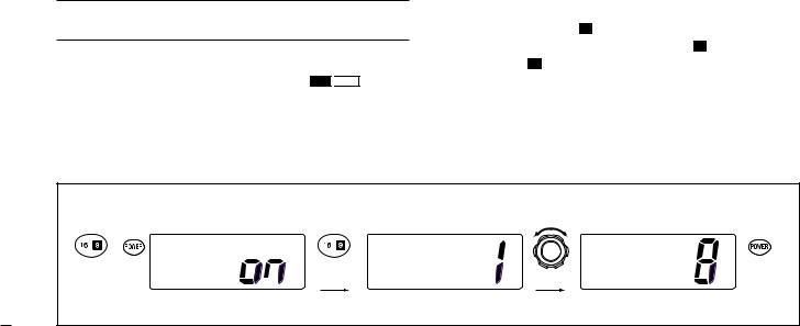
q Turn power OFF.
w While pushing [16] ( 9 ), turn power ON to enter Set mode. e After the display appears, release [16] ( 9 ).
rPush [16] ( 9 ) one or more times to select the scrambler code.
• “Scrambler Code” appears.
t Rotate [CHANNEL] to select the desired scrambler code. y Turn power OFF, then ON again to exit Set mode.
[Example]: Programming scrambler code 8.
+ |
Set Mode |
|
Set Mode |
Set Mode |
|
|
|
|
|
|
|
Enter Set mode Beep |
Push one or |
Scrambler |
Scrambler |
Turn OFF |
|
|
|
more times. |
Code |
Select code Code |
|
|
Set mode |
|
Scrambler code item |
|
|
9
3. Dualwatch/Tri-Watch
3.1 Description
Dualwatch monitors Channel 16 while you are receiving another channel; Tri-watch monitors Channel 16 and call channel while receiving another channel.
DUALWATCH/TRI-WATCH SIMULATION
Call channel
Dualwatch |
Tri-watch |
•If a signal is received on Channel 16, Dualwatch/Tri-watch pauses on Channel 16 until the signal disappears.
•If a signal is received on call channel during Tri-watch, Tri-watch becomes Dualwatch until the signal disappears.
•To transmit on the selected channel during Dualwatch/Tri-watch, push and hold [PTT].
3.2 Operation
q Select Dualwatch or Tri-watch in Set mode. (p. 38) w Select the desired operating channel.
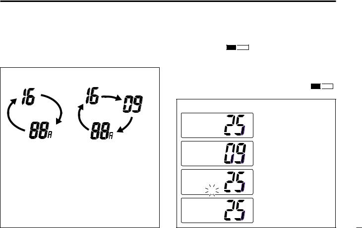
ePush [CH/WX] ( DW 
 U/I/C ) for 1 sec. to start Dualwatch or Tri-watch.
•“DUAL” appears during Dualwatch; “TRI” appears during Triwatch.
•A beep tone sounds when a signal is received on Channel 16. r To cancel Dualwatch or Tri-watch, push [CH/WX] ( DW 
 U/I/C )
again.
[Example]: Operating Tri-watch on INT Channel 25.
|
INT |
Tri-watch starts. |
|
25W |
|
||
|
|
||
TAG |
DUP |
|
|
TRI |
16 |
|
|
BUSY |
INT |
Signal is received |
|
25W |
CALL |
||
on call channel. |
|||
TAG |
|
||
TRI |
16 |
|
|
BUSY |
INT |
Signal received on |
|
25W |
|
||
|
Channel 16 takes |
||
TAG |
DUP |
||
TRI |
16 |
priority. |
|
|
INT |
Tri-watch resumes |
|
25W |
|
||
|
after the signal |
||
TAG |
DUP |
||
disappears. |
|||
TRI |
16 |
10
4. Scan Operation
4.1 Scan Types
Scanning is an efficient way to locate signals quickly over a wide frequency range. The transceiver has Priority scan and Normal scan.
When the Weather alert function is in use, the selected weather channel is checked while scanning. (p. 38)
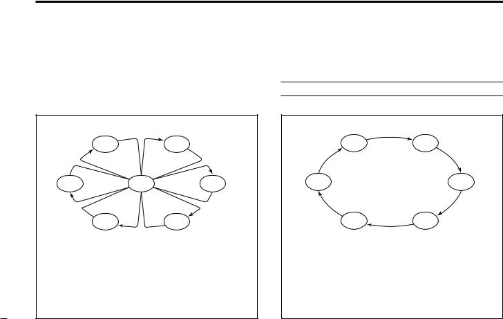
PRIORITY SCAN
|
CH 01 |
CH 02 |
CH 06 |
CH 16 |
CH 03 |
|
CH 05 |
CH 04 |
Priority scan searches through all tag channels in sequence while monitoring Channel 16. When a signal is detected on Channel 16, scan pauses until the signal disappears; when a signal is detected on a channel other than Channel 16, scan becomes Dualwatch until the signal disappears.
Set the tag channels (scanned channel) before scanning. Clear the tag channels which inconveniently stop scanning, such as those for digital communication use.
Note: Choose Priority or Normal scan in Set mode. (p. 38)
NORMAL SCAN
CH 01 |
CH 02 |
CH 06 |
CH 03 |
CH 05 |
CH 04 |
Normal scan, like Priority scan, searches through all tag channels in sequence. However, unlike Priority scan, Channel 16 is not checked unless Channel 16 is set as a tag channel.
1
4.Scan Operation
4.2 Setting Tag Channels
For more efficient scanning, add desired channels as tag channels or clear tag channels for unwanted channels. Channels not tagged will be skipped during scanning. Tag channels can be assigned to each channel group (U.S.A., International, Canada) independently.
qWhile pushing [HI/LO], push [CH/WX] ( DW 
 U/I/C ) one or more times to select the desired channel group.
w Select the desired channel to be set as a tag channel.
ePush [SCAN] ( TAG ) for 1 sec. to set the displayed channel as a tag channel.
• “TAG” appears in the display.
rTo cancel the tag channel setting, repeat step e.
• “TAG” disappears.
Convinient: Clearing (setting) all tagged channels
While pushing [HI/LO], push [SCAN] ( TAG ) for 3 sec. (until a long beep changes to 2 short beeps) to clear all tag channels setting in the channel group.
•Repeat above procedure to set all tag channels.
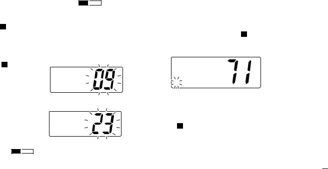
4.3 Starting a Scan
Set scan type (Priority or Normal scan) and scan resume timer in advance using Set mode. (p. 38)
q Set tag channels as described at left.
w Make sure the squelch is closed to start a scan.
eWhile pushing [HI/LO], push [CH/WX] ( DW 
 U/I/C ) one or more times to select the channel group, if desired.
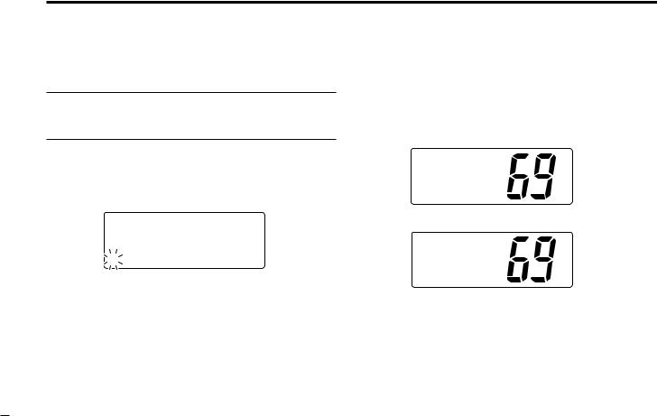
rPush [SCAN] to start Priority or Normal scan.
•“Pri Scan 16” or “Normal Scan” appears in the function display.
•When a signal is detected, scan pauses until the signal disappears or resumes after pausing 5 sec. according to Set mode setting. (Channel 16 is still monitored during Priority scan.)
•Rotate [CHANNEL] to check the scanning tag channels, to change the scanning direction or resume the scan manually.
•“16” blinks and a beep tone sounds when a signal is received on Channel 16 during Priority scan.
t To stop the scan, push [SCAN].
[Example]: Starting a Normal scan.
|
INT |
Push |
INT |
BUSY |
INT |
25W |
|
25W |
|
25W |
|
TAG |
DUP |
TAG |
DUP |
TAG |
DUP |
INTL |
|
Normal scan |
Normal scan |
||
|
|
|
Scan starts. |
When a signal is received |
|
12
5. DSC Operation
5.1 MMSI Code Programming
The 9-digit MMSI (Maritime Mobile Service Identity: DSC self ID) code can be programmed at power ON.
Note: This function is not available when the MMSI code has been programmed by the dealer. This code programming can be performed only twice.
q Turn power OFF.
wWhile pushing [DSC/ENT], turn power ON to enter MMSI code programming condition.
e After the display appears, release [DSC/ENT].
Set MMSI
ä23456789
rEdit the specific MMSI code by rotating [CHANNEL].
•Push [CH/WX] or [SCAN] to move the cursor forward or backward, respectively.
tInput the 9 digit codes, then push [DSC/ENT] to set the code.
• Returns to the normal operation.
5.2 DSC Individual ID
A total of 40 DSC address IDs can be programmed and named with up to 10 characters.
DProgramming Address ID/Group ID q Push [DSC/ENT] to enter the DSC menu.
wRotate [CHANNEL] to select “Set up,” push
[DSC/ENT].
Sel Item POS Report DTRS Set
˘Set up
e Rotate [CHANNEL] to select “Add ID,” push [DSC/ENT].
Set up ˘Add ID
Delete ID Offset Time
3
rSet the individual ID and ID name.
•Edit the 9 digits of the appropriate distress ID by using [CHANNEL].
-Push [CH/WX] or [SCAN] to move the cursor forward or backward, respectively.
Note: 1st digit ‘0’ is fixed for a group ID. Thus an address ID input cannot started with ‘0.’ When you input 1st digit ‘0’ and other 8 digits, the ID is automatically registered as a group ID.
Add ID
ID:4
NAME:
tPush [DSC/ENT] to program and exit the condition to the normal operation.
5.DSC Operation
DDeleting Address ID/Group ID q Push [DSC/ENT] to enter the DSC menu.
wRotate [CHANNEL] to select “Set up,” push
[DSC/ENT].
eRotate [CHANNEL] to select “Delete ID,” push
[DSC/ENT].
•When no address ID is programmed, the transceiver exits the DSC menu automatically.
Set up Add ID
˘Delete ID Offset Time
rRotate [CHANNEL] to select the desired ID name for deleting.
Delete ID ˘Bill
Ricky Tom
tThe delete confirmation display will appear when
[DSC/ENT] is pushed.
•Push [HI/LO] to delete ID and exit the DSC Menu.
•Push [DSC/ENT] to cancel deleting and exit the DSC Menu.
14
 Loading...