


 Loading...
Dell Precision™ T5400 User’s Guide
Model DCTA
w w w . d e l l . c o m | s u p p o r t . d e l l . c o m

Notes, Notices, and Cautions
NOTE: A NOTE indicates important information that helps you make better use of your computer.
NOTICE: A NOTICE indicates either potential damage to hardware or loss of data and tells you how to avoid the problem.
CAUTION: A CAUTION indicates a potential for property damage, personal injury, or death.
____________________
Information in this document is subject to change without notice. © 2007 Dell Inc. All rights reserved.
Reproduction in any manner whatsoever without the written permission of Dell Inc. is strictly forbidden.
Trademarks used in this text: Dell, the DELL logo, Dell Precision, and Dell OpenManage are trademarks of Dell Inc.; Intel, Speedstep, and Xeon are registered trademarks of Intel Corporation; Microsoft, Windows, and Windows Vista are either trademarks or registered trademarks of Microsoft Corporation in the United States and/or other countries.
Other trademarks and trade names may be used in this document to refer to either the entities claiming the marks and names or their products. Dell Inc. disclaims any proprietary interest in trademarks and trade names other than its own.
Model DCTA
August 2007 |
P/N NX046 Rev. A00 |

Contents
1Finding Information . . . . . . . . . . . . . . . . . 11
2About Your Computer . . . . . . . . . . . . . . . 19
Front View of the Computer (Tower Orientation) . . . . |
19 |
Back View of the Computer (Tower Orientation) . . . . |
21 |
Back Panel Connectors (Tower Orientation) . . . |
22 |
Front View (Desktop Orientation) . . . . . . . . . . . . |
24 |
Back View (Desktop Orientation) . . . . . . . . . . . . |
25 |
Inside View . . . . . . . . . . . . . . . . . . . . . . . |
26 |
Inside View – Hard Drive Bay Rotated Out . . . . |
27 |
System Board Components . . . . . . . . . . . . . . . |
28 |
Cable Colors . . . . . . . . . . . . . . . . . . . . |
29 |
Changing Between Tower and Desktop Modes . . . . |
30 |
Specifications . . . . . . . . . . . . . . . . . . . . . . |
36 |
3 Advanced Features . . . . . . . . . . . . . . . . . 45
LegacySelect Technology Control . . . . . . . . . . . |
45 |
Manageability . . . . . . . . . . . . . . . . . . . . . . |
45 |
Alert Standard Format . . . . . . . . . . . . . . . |
45 |
Dell OpenManage™ IT Assistant . . . . . . . . . |
47 |
Contents 3
Dell OpenManage Client Instrumentation . . . . . |
47 |
Power Management . . . . . . . . . . . . . . . . . . . |
47 |
About RAID Configurations . . . . . . . . . . . . . . . |
49 |
RAID Level 0 . . . . . . . . . . . . . . . . . . . . |
50 |
RAID Level 1 . . . . . . . . . . . . . . . . . . . . |
51 |
RAID Level 5 . . . . . . . . . . . . . . . . . . . . |
51 |
Configuring Your Computer for RAID . . . . . . . . |
53 |
Configuring Your Computer for RAID Using the |
|
Intel Matrix Storage Manager . . . . . . . . . . . |
53 |
Configuring Your Computer for RAID Using the |
|
Intel® RAID Option ROM Utility . . . . . . . . . . |
61 |
|
|
4 Setting Up Your Computer . . . . . . . . . . . . |
65 |
|
|
Installing Your Computer in an Enclosure . . . . . . . |
65 |
|
|
Connecting to the Internet . . . . . . . . . . . . . . . . |
67 |
|
|
Setting Up Your Internet Connection . . . . . . . . |
68 |
|
|
Transferring Information to a New Computer . . . . . . |
69 |
|
|
Microsoft® Windows® XP . . . . . . . . . . . . . |
70 |
|
|
Microsoft Windows Vista™ . . . . . . . . . . . . |
73 |
|
|
Power Protection Devices . . . . . . . . . . . . . . . |
73 |
|
|
Surge Protectors . . . . . . . . . . . . . . . . . . |
74 |
|
|
Line Conditioners . . . . . . . . . . . . . . . . . . |
74 |
|
|
Uninterruptible Power Supplies . . . . . . . . . . |
74 |
|
|
5 Securing Your Computer . . . . . . . . . . . . . |
75 |
|
|
Chassis Intrusion Detection . . . . . . . . . . . . . . . |
75 |
|
|
Removing the Chassis Intrusion Switch . . . . . . |
75 |
|
|
Replacing the Chassis Intrusion Switch . . . . . . |
76 |
4 |
|
Contents |
|
|
|

Resetting the Chassis Intrusion Detector . . . . . |
76 |
Security Cable Lock . . . . . . . . . . . . . . . . . . . |
77 |
Passwords . . . . . . . . . . . . . . . . . . . . . . . . |
78 |
About Passwords . . . . . . . . . . . . . . . . . |
78 |
Using a Primary (or System) Password . . . . . . |
79 |
Using an Administrator Password . . . . . . . . . |
82 |
Disabling a Forgotten Password and Setting a |
|
New Password . . . . . . . . . . . . . . . . . . . |
84 |
Trusted Platform Module (TPM) . . . . . . . . . . . . . |
85 |
Enabling the TPM Feature . . . . . . . . . . . . . |
85 |
Security Management Software . . . . . . . . . . . . |
86 |
Activating the Security Management Software . . |
86 |
Using the Security Management Software . . . . |
86 |
Computer Tracking Software . . . . . . . . . . . . . . |
86 |
If Your Computer Is Lost or Stolen . . . . . . . . . . . |
87 |
6 System Setup . . . . . . . . . . . . . . . . . . . . . . 89
Overview . . . . . . . . . . . . . . . . . . . . . . . . |
89 |
Entering System Setup . . . . . . . . . . . . . . . . . |
89 |
System Setup Options . . . . . . . . . . . . . . . . . . |
89 |
Boot Menu . . . . . . . . . . . . . . . . . . . . . . . . |
97 |
Option Settings . . . . . . . . . . . . . . . . . . . |
98 |
Selecting the Boot Device for the Current Boot . . |
98 |
Changing Boot Sequence for Future Boots . . . . |
99 |
Booting to a USB Device . . . . . . . . . . . . . . |
99 |
Contents 5

7 |
Clearing Forgotten Passwords . . . . . . . |
101 |
|
Clearing CMOS Settings . . . . . . . . . . . . . . . . . |
103 |
|
Flashing the BIOS . . . . . . . . . . . . . . . . . . . . |
103 |
8 |
Cleaning Your Computer . . . . . . . . . . . . |
105 |
|
Computer, Keyboard, and Monitor . . . . . . . . . |
105 |
|
Floppy Drive . . . . . . . . . . . . . . . . . . . . |
105 |
|
CDs and DVDs . . . . . . . . . . . . . . . . . . . |
105 |
9 Troubleshooting . . . . . . . . . . . . . . . . . . . |
107 |
|
|
Solving Problems . . . . . . . . . . . . . . . . . . . . |
107 |
|
Battery Problems . . . . . . . . . . . . . . . . . . |
107 |
|
Drive Problems . . . . . . . . . . . . . . . . . . . |
107 |
|
E-Mail and Internet Problems . . . . . . . . . . . |
109 |
|
Error Messages . . . . . . . . . . . . . . . . . . |
110 |
|
IEEE 1394 Device Problems . . . . . . . . . . . . . |
111 |
|
Keyboard Problems . . . . . . . . . . . . . . . . . |
112 |
|
Lockups and Software Problems . . . . . . . . . . |
112 |
|
Memory Problems . . . . . . . . . . . . . . . . . |
114 |
|
Mouse Problems . . . . . . . . . . . . . . . . . . |
115 |
|
Network Problems . . . . . . . . . . . . . . . . . |
116 |
|
Power Problems . . . . . . . . . . . . . . . . . . |
116 |
|
Printer Problems . . . . . . . . . . . . . . . . . . |
117 |
|
Scanner Problems . . . . . . . . . . . . . . . . . |
118 |
|
Sound Problems . . . . . . . . . . . . . . . . . . |
119 |
10 |
Troubleshooting Tools . . . . . . . . . . . . . . |
121 |
|
Diagnostic Lights . . . . . . . . . . . . . . . . . . . . |
121 |
6 Contents

|
Diagnostic Light Codes Before POST . . . . . . . |
121 |
|
Diagnostic Light Codes During POST . . . . . . . |
123 |
|
Beep Codes . . . . . . . . . . . . . . . . . . . . . . . |
129 |
|
Error Messages . . . . . . . . . . . . . . . . . . . . . |
130 |
|
Dell Diagnostics . . . . . . . . . . . . . . . . . . . . . |
136 |
|
When to Use the Dell Diagnostics . . . . . . . . . |
136 |
|
Starting the Dell Diagnostics From Your Hard |
|
|
Drive . . . . . . . . . . . . . . . . . . . . . . . . |
137 |
|
Starting the Dell Diagnostics From the Drivers and |
|
|
Utilities Disc . . . . . . . . . . . . . . . . . . . . |
137 |
|
Dell Diagnostics Main Menu . . . . . . . . . . . . |
138 |
11 |
Reinstalling Software . . . . . . . . . . . . . . |
141 |
|
Drivers . . . . . . . . . . . . . . . . . . . . . . . . . . |
141 |
|
What Is a Driver? . . . . . . . . . . . . . . . . . . |
141 |
|
Identifying Drivers . . . . . . . . . . . . . . . . . |
141 |
|
Reinstalling Drivers and Utilities . . . . . . . . . . |
142 |
|
Troubleshooting Software and Hardware Problems in |
|
|
the Microsoft® Windows® XP and Microsoft Windows |
|
|
Vista™ Operating Systems . . . . . . . . . . . . . . . |
143 |
|
Restoring Your Operating System . . . . . . . . . . . . |
144 |
|
Using Microsoft Windows System Restore . . . . |
144 |
|
Using Dell™ PC Restore and Dell Factory Image |
|
|
Restore . . . . . . . . . . . . . . . . . . . . . . . |
146 |
|
Using the Operating System Disc . . . . . . . . . |
149 |
12 |
Adding and Replacing Parts . . . . . . . . . |
151 |
|
Before You Begin . . . . . . . . . . . . . . . . . . . . |
151 |
Contents 7

Recommended Tools . . . . . . . . . . . . . . . . |
151 |
Turning Off Your Computer . . . . . . . . . . . . . |
151 |
Before Working Inside Your Computer . . . . . . . |
152 |
Removing the Computer Cover and Front Panel . . . . |
153 |
Removing the Computer Cover . . . . . . . . . . . |
153 |
Removing the Front Panel . . . . . . . . . . . . . |
155 |
Rotating the Hard Drive Carrier Out of the |
|
Computer . . . . . . . . . . . . . . . . . . . . . . |
156 |
Replacing the Front Panel and Computer Cover . . . . |
158 |
Rotating the Hard-Drive Carrier Back into the |
159 |
Computer . . . . . . . . . . . . . . . . . . . . . . |
|
Replacing the Front Panel . . . . . . . . . . . . . |
160 |
Replacing the Computer Cover . . . . . . . . . . . |
161 |
I/O Panel . . . . . . . . . . . . . . . . . . . . . . . . . |
163 |
I/O-Panel Components . . . . . . . . . . . . . . . |
164 |
Removing the I/O Panel . . . . . . . . . . . . . . |
165 |
Replacing the I/O Panel . . . . . . . . . . . . . . |
167 |
Power Supply . . . . . . . . . . . . . . . . . . . . . . |
167 |
Power Supply DC Connector Pin Assignments . . |
167 |
Removing the Power Supply . . . . . . . . . . . . |
174 |
Replacing the Power Supply . . . . . . . . . . . . |
176 |
Battery . . . . . . . . . . . . . . . . . . . . . . . . . . |
176 |
About the Battery . . . . . . . . . . . . . . . . . . |
176 |
Replacing the Battery . . . . . . . . . . . . . . . |
177 |
Processor . . . . . . . . . . . . . . . . . . . . . . . . |
179 |
Removing the Processor . . . . . . . . . . . . . . |
179 |
Installing the Processor . . . . . . . . . . . . . . |
183 |
Memory . . . . . . . . . . . . . . . . . . . . . . . . . |
187 |
Fully Buffered DIMM (FBD) Memory Overview . . |
187 |
8 Contents
Addressing Memory With 4-GB or Greater
Configurations (32-bit Operating Systems Only) . . 188
Removing Memory . . . . . . . . . . . . . |
. . . . |
189 |
|
|
Installing Memory . . . . . . . . . . . . . |
. . . . |
190 |
|
|
Cards . . . . . . . . . . . . . . . . . . . . . . . |
. . . . |
193 |
|
|
Expansion Card Support . . . . . . . . . . |
. . . . |
193 |
|
|
Installing an Expansion Card . . . . . . . . |
. . . . |
194 |
|
|
Removing an Expansion Card . . . . . . . |
. . . . |
201 |
|
|
Drives . . . . . . . . . . . . . . . . . . . . . . |
. . . . |
205 |
|
|
Tower Computer Drives . . . . . . . . . . |
. . . . |
205 |
|
|
Desktop Computer Drives . . . . . . . . . |
. . . . |
206 |
|
|
Controller Card Data Cable Connectors . . |
. . . . |
212 |
|
|
Hard Drive . . . . . . . . . . . . . . . . . |
. . . . |
212 |
|
|
Drive Panels . . . . . . . . . . . . . . . . |
. . . . |
233 |
|
|
Floppy Drive . . . . . . . . . . . . . . . . |
. . . . |
239 |
|
|
Media Card Reader . . . . . . . . . . . . |
. . . . |
254 |
|
|
Optical Drive . . . . . . . . . . . . . . . . |
. . . . |
268 |
|
|
System Board . . . . . . . . . . . . . . . . . . |
. . . . |
281 |
|
|
Removing the System Board . . . . . . . . |
. . . . |
281 |
|
|
Replacing the System Board . . . . . . . . |
. . . . |
284 |
|
|
13 Getting Help . . . . . . . . . . . . . . . . . . |
. . . 289 |
|
|
|
Obtaining Assistance . . . . . . . . . . . . . . |
. . . . |
289 |
|
|
Technical Support and Customer Service . |
. . . . |
290 |
|
|
Online Services . . . . . . . . . . . . . . |
. . . . |
290 |
|
|
AutoTech Service . . . . . . . . . . . . . |
. . . . |
291 |
|
|
Automated Order-Status Service . . . . . |
. . . . |
291 |
|
|
Problems With Your Order . . . . . . . . . . . |
. . . . |
291 |
|
|
Product Information . . . . . . . . . . . . . . . |
. . . . |
291 |
|
|
|
Contents |
|
|
9 |
|
|
|||

Returning Items for Warranty Repair or Credit . . . . . |
292 |
Before You Call . . . . . . . . . . . . . . . . . . . . . |
292 |
Contacting Dell . . . . . . . . . . . . . . . . . . . . . |
295 |
A Appendix . . . . . . . . . . . . . . . . . . . . . . . . |
297 |
FCC Notice (U.S. Only) . . . . . . . . . . . . . . . . . . |
297 |
FCC Class B . . . . . . . . . . . . . . . . . . . . . |
297 |
Glossary . . . . . . . . . . . . . . . . . . . . . . . . . . . . |
299 |
10 Contents
1
Finding Information
NOTE: Some features or media may be optional and may not ship with your computer. Some features or media may not be available in certain countries.
NOTE: Additional information may ship with your computer.
Finding Information |
|
11 |
|

What Are You Looking For? |
Find It Here |
|
• A diagnostic program for my computer |
Drivers and Utilities Disc |
|
• Drivers for my computer |
Documentation and drivers are already |
|
• Desktop System Software (DSS) |
installed on your computer. You can use |
|
the Drivers and Utilities disc to reinstall |
||
|
||
|
drivers (see "Reinstalling Drivers and |
|
|
Utilities" on page 142), or to run the Dell |
|
|
Diagnostics (see "Dell Diagnostics" on |
|
|
page 136). |
|
|
Readme files may be included on your |
|
|
Drivers and Utilities disc to provide last- |
|
|
minute updates about technical changes |
|
|
to your computer or advanced technical- |
|
|
reference material for technicians or |
|
|
experienced users. |
NOTE: Drivers and documentation updates can be found at support.dell.com.
12 |
|
Finding Information |
|
What Are You Looking For? |
Find It Here |
• How to set up my computer |
Quick Reference Guide |
• How to care for my computer |
NOTE: This document may be optional and |
• Basic troubleshooting information |
may not ship with your computer. |
|
|
• How to run the Dell Diagnostics |
|
• How to set up a printer |
|
• How to open my computer |
|
|
NOTE: This document is available as a PDF |
|
at support.dell.com. |
• Warranty information |
Dell™ Product Information Guide |
•Terms and Conditions (U.S. only)
•Safety instructions
•Regulatory information
•Ergonomics information
•End User License Agreement
Finding Information |
|
13 |
|

What Are You Looking For?
•Service Tag and Express Service Code
•Microsoft Windows License Label
Find It Here
Service Tag and Microsoft® Windows®
License
These labels are located on your computer.
•Use the Service Tag to identify your computer when you use support.dell.com or contact support.
•Enter the Express Service Code to direct your call when contacting support.
NOTE: As an increased security measure, the newly designed Microsoft Windows license label incorporates a missing portion or "hole" to discourage removal of the label.
14 |
|
Finding Information |
|

What Are You Looking For?
•Solutions — Troubleshooting hints and tips, articles from technicians, and online courses, frequently asked questions
•Community — Online discussion with other Dell customers
•Upgrades — Upgrade information for components, such as memory, the hard drive, and the operating system
•Customer Care — Contact information, service call and order status, warranty, and repair information
•Service and support — Service call status and support history, service contract, online discussions with technical support
•Dell Technical Update Service — Proactive e-mail notification of software and hardware updates for your computer
•Reference — Computer documentation, details on my computer configuration, product specifications, and white papers
•Downloads — Certified drivers, patches, and software updates
•Desktop System Software (DSS)— If you reinstall the operating system for your computer, you should also reinstall the DSS utility. DSS provides critical updates for your operating system and support for processors, optical drives, USB devices, and so on. DSS is necessary for correct operation of your Dell computer. The software automatically detects your computer and operating system and installs the updates appropriate for your configuration.
Find It Here
Dell Support Website — support.dell.com
NOTE: Select your region or business segment to view the appropriate support site.
To download Desktop System Software:
1 Go to support.dell.com, select your region or business segment, and enter your Service Tag.
2 Select Drivers & Downloads and click Go.
3 Click your operating system and search for the keyword Notebook System Software.
NOTE: The support.dell.com user interface may vary depending on your selections.
Finding Information |
|
15 |
|

What Are You Looking For? |
Find It Here |
|
|
|
|
• How to use Microsoft Windows Vista™ |
Windows Help and Support |
|
• How to work with programs and files |
1 Click the Windows Vista Start button |
|
• How to personalize my desktop |
, and then click Help and Support. |
|
2 In Search Help, type a word or phrase |
||
|
||
|
that describes your problem, and then |
|
|
press <Enter> or click the magnifying |
|
|
glass. |
|
|
3 Click the topic that describes your |
|
|
problem. |
|
|
4 Follow the instructions on the screen. |
|
• How to reinstall my operating system |
Operating System Disc |
|
|
NOTE: The Operating System disc may be |
|
|
optional and may not ship with your |
|
|
computer. |
|
|
The operating system is already installed |
|
|
on your computer. To reinstall your |
|
|
operating system, use the Operating |
|
|
System disc (see "Reinstalling Windows |
|
|
XP or Windows Vista" on page 149). |
After you reinstall your operating system, use the Drivers and Utilities disc to reinstall drivers for the devices that came with your computer.
Your operating system product key label is located on your computer.
NOTE: The color of your disc varies based on the operating system you ordered.
16 |
|
Finding Information |
|

What Are You Looking For?
•How to use Linux
•E-mail discussions with users of Dell Precision™ products and the Linux operating system
•Additional information regarding Linux and my Dell Precision computer
Find It Here
Dell Supported Linux Sites
•Linux.dell.com
•Lists.us.dell.com/mailman/listinfo/linuxprecision
Finding Information |
|
17 |
|
18 |
|
Finding Information |
|

2
About Your Computer
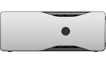
Front View of the Computer (Tower Orientation)
|
1 |
|
2 |
12 |
3 |
|
|
11 |
4 |
10 |
|
9 |
5 |
8 |
6 |
|
|
|
7 |
1 |
upper 5.25-inch drive |
Use this bay for an optical drive. |
|
bay |
|
2 |
lower 5.25-inch drive |
Use this bay for an optional optical drive. |
|
bay |
|
3 |
FlexBay |
Use this bay for an optional third hard drive (SATA or |
|
|
SAS), a floppy drive, or a Media Card Reader. |
4 |
hard-drive activity |
The hard drive light is on when the computer reads data |
|
light |
from or writes data to the hard drive. The light might also |
|
|
be on when a device, such as your CD drive, is operating. |
About Your Computer |
|
19 |
|

5 |
IEEE 1394 connector |
Use the optional IEEE 1394 connector for high-speed |
|
(optional) |
data devices such as digital video cameras and external |
|
|
storage devices. |
6 USB 2.0 connectors (2) |
Use the front USB connectors for devices that you |
|
|
|
connect occasionally, such as flash memory keys or |
|
|
cameras, or for bootable USB devices (see "System |
|
|
Setup" on page 89 for more information on booting to a |
|
|
USB device). |
|
|
It is recommended that you use the back USB |
|
|
connectors for devices that typically remain connected, |
|
|
such as printers and keyboards. |
7 |
Dell™ rotatable badge |
To rotate the Dell badge for tower-to-desktop |
|
|
conversion: remove the front panel (see "Removing the |
|
|
Computer Cover" on page 153), turn it over, and rotate the |
|
|
plastic handle behind the badge. |
8 |
power button, |
Press the power button to turn on the computer. The light |
|
power light |
in the center of this button indicates power state. See |
|
|
"Controls and Lights" on page 40 for more information. |
|
|
NOTICE: To avoid losing data, do not use the |
|
|
power button to turn off the computer. Instead, |
|
|
perform an operating system shutdown. |
9 |
headphone connector |
Use the headphone connector to attach headphones. |
10 |
microphone connector |
Use the microphone connector to attach a personal |
|
|
computer microphone for voice or musical input into a |
|
|
sound or telephony program. |
11 |
network link light |
The network link light is on when a good connection |
|
|
exists between a 10-Mbps, 100-Mbps, or 1000-Mbps (or |
|
|
1-Gbps) network and the computer. |
12 |
diagnostic lights (4) |
Use these lights to help you troubleshoot a computer |
|
|
problem based on the diagnostic code. For more |
|
|
information, see "Diagnostic Lights" on page 121. |
20 |
|
About Your Computer |
|
Back View of the Computer (Tower Orientation)
1
2
3
|
|
|
|
|
1 |
power connector |
Insert the power cable. |
||
2 |
card slots |
Access connectors for any installed PCI and PCI Express |
||
|
|
cards. |
||
|
|
The center four connector slots support full-length cards, and |
||
|
|
the connector slots on either the top or bottom (one x8 PCI |
||
|
|
Express slot (wired as x4) and one PCI-X card) support half- |
||
|
|
length cards. |
||
3 |
back panel |
Plug USB, audio, and other devices into the appropriate |
||
|
connectors |
connector (see "Back Panel Connectors (Tower Orientation)" |
||
|
|
on page 22 for more information. |
||
CAUTION: Ensure that none of the system air vents are blocked. Blocking them will cause serious thermal problems.
About Your Computer |
|
21 |
|
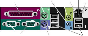
Back Panel Connectors (Tower Orientation)
1 |
2 |
3 |
4 |
5 |
6 |
7 |
8 |
|
9 |
|
|
|
10 |
1 |
parallel connector |
Connect a parallel device, such as a printer, to the parallel |
|
|
connector. If you have a USB printer, plug it into a USB |
|
|
connector. |
|
|
The integrated parallel connector is automatically disabled if |
|
|
the computer detects an installed card containing a parallel |
|
|
connector configured to the same address. For more |
|
|
information, see "System Setup Options" on page 89. |
2 |
PS/2 mouse |
Plug a standard PS/2 mouse into the green mouse connector. |
|
connector |
Turn off the computer and any attached devices before you |
|
|
connect a mouse to the computer. If you have a USB mouse, |
|
|
plug it into a USB connector. |
3 |
line-in connector |
Use the blue line-in connector to attach a playback device |
|
|
such as an MP3 player, CD player, or VCR. |
|
|
On computers with a sound card, use the connector on the |
|
|
card. |
4 |
line-out connector |
Use the green line-out connector to attach most speakers with |
|
|
integrated amplifiers. |
|
|
On computers with a sound card, use the connector on the |
|
|
card. |
5 |
link integrity light |
Green — A good connection exists between a 10-Mbps |
|
|
network and the computer. |
|
|
Orange — A good connection exists between a 100-Mbps |
network and the computer.
Yellow — A good connection exists between a 1000-Mbps (or 1-Gbps) network and the computer.
Off — The computer is not detecting a physical connection to the network.
22 |
|
About Your Computer |
|
6 |
network adapter |
To attach your computer to a network or broadband device, |
|
|
connector |
connect one end of a network cable to either a network jack or |
|
|
|
your network or broadband device. Connect the other end of |
|
|
|
the network cable to the network adapter connector on your |
|
|
|
computer. A click indicates that the network cable has been |
|
|
|
securely attached. |
|
|
|
Do not plug a telephone cable into the network connector. |
|
|
|
On computers with an additional network connector card, use |
|
|
|
the connectors on the card and on the back of the computer |
|
|
|
when setting up multiple network connections (such as a |
|
|
|
separate intraand extranet). |
|
|
|
It is recommended that you use Category 5 wiring and |
|
|
|
connectors for your network. If you must use Category 3 |
|
|
|
wiring, force the network speed to 10 Mbps to ensure reliable |
|
|
|
operation. |
|
7 |
network activity |
Flashes a yellow light when the computer is transmitting or |
|
|
light |
receiving network data. A high volume of network traffic may |
|
|
|
make this light appear to be in a steady "on" state. |
|
8 |
serial connectors |
Connect a serial device, such as a handheld device, to the |
|
|
(2) |
serial port. If necessary,1 |
the address for this port can be |
|
|
modified through "System Setup" on page 89. |
|
9 |
PS/2 keyboard |
If you have a standard PS/2 keyboard, plug it into the purple |
|
|
connector |
keyboard connector. If you have a USB keyboard, plug it into a |
|
|
|
USB connector. |
|
10 |
USB 2.0 |
It is recommended that you use the front USB connectors for |
|
|
connectors (5) |
devices that you connect occasionally, such as flash memory |
|
|
|
keys or cameras, or for bootable USB devices. |
|
|
|
Use the back USB connectors for devices that typically remain |
|
|
|
connected, such as printers and keyboards. |
|
About Your Computer |
|
23 |
|
Front View (Desktop Orientation)
1 |
2 |
3 |
|
|
|
|
4 |
5 |
6 |
7 |
||||||
|
|
|
|
|
|
|
|
|
|
|
|
|
|
|
|
|
|
|
|
|
|
|
|
|
|
|
|
|
|
|
|
|
|
|
|
|
|
|
|
|
|
|
|
|
|
|
|
|
|
|
|
|
|
|
|
|
|
|
|
|
|
|
|
|
|
|
|
|
|
|
|
|
|
|
|
|
|
|
|
|
|
|
|
|
|
|
|
|
|
|
|
|
|
|
|
|
|
|
|
|
|
|
|
|
|
|
|
|
|
|
|
|
|
|
|
|
|
|
|
|
|
|
|
|
|
|
|
|
|
|
|
|
|
|
|
|
|
|
|
|
|
|
|
|
|
|
|
|
|
|
|
|
|
12 |
11 |
10 |
9 |
8 |
1 |
upper 5.25-inch |
|
Use this bay for an an optical drive. |
||
|
drive bay |
|
|
|
|
2 |
lower 5.25-inch |
|
Use this bay for an optional optical drive or a SATA hard drive. |
||
|
drive bay |
|
|
|
|
3 |
FlexBay |
|
Use this bay for a floppy drive or a Media Card Reader. |
||
4 |
IEEE 1394 |
|
Use the optional IEEE 1394 connector for high-speed data |
||
|
connector |
|
devices such as digital video cameras and external storage |
||
|
(optional) |
|
devices. |
|
|
5 |
USB 2.0 |
|
Use the front USB connectors for devices that you connect |
||
|
connectors (2) |
|
occasionally, such as flash memory keys or cameras, or for |
||
|
|
|
bootable USB devices (see "System Setup" on page 89 for more |
||
|
|
|
information on booting to a USB device). |
||
|
|
|
It is recommended that you use the back USB connectors for |
||
|
|
|
devices that typically remain connected, such as printers and |
||
|
|
|
keyboards. |
|
|
6 |
hard-drive activity |
The hard drive light is on when the computer reads data from |
|||
|
light |
|
or writes data to the hard drive. The light might also be on |
||
|
|
|
when a device such as your CD player is operating. |
||
24 |
|
About Your Computer |
|

7 |
Dell™ rotatable |
|
To rotate the Dell badge for tower-to-desktop conversion: |
|||||||||
|
badge |
|
remove the front panel (see "Removing the Front Panel" on |
|||||||||
|
|
|
|
|
page 155), turn it over, and rotate the plastic handle behind the |
|||||||
|
|
|
|
|
badge. |
|
|
|
||||
8 |
power button, |
|
Press the power button to turn on the computer. The light in |
|||||||||
|
power light |
|
the center of this button indicates power state. See |
|||||||||
|
|
|
|
|
"Diagnostic Lights" on page 121 for more information. |
|||||||
|
|
|
|
|
|
|
|
NOTICE: To avoid losing data, do not use the power |
||||
|
|
|
|
|
|
|
button to turn off the computer. Instead, perform an |
|||||
|
|
|
|
|
|
|
operating system shutdown. |
|
|
|
||
9 |
headphone |
|
Use the headphone connector to attach headphones. |
|||||||||
|
connector |
|
|
|
|
|
|
|
|
|
||
10 |
microphone |
|
Use the microphone connector to attach a personal computer |
|||||||||
|
connector |
|
microphone for voice or musical input into a sound or |
|||||||||
|
|
|
|
|
telephony program. |
|
|
|
||||
11 |
network link light |
|
The network link light is on when a good connection exists |
|||||||||
|
|
|
|
|
between a 10-Mbps, 100-Mbps, or 1000-Mbps (or 1-Gbps) |
|||||||
|
|
|
|
|
network and the computer. |
|
|
|
||||
12 |
diagnostic lights |
|
Use these lights to help you troubleshoot a computer problem |
|||||||||
|
(4) |
|
|
|
based on the diagnostic code. For more information, see |
|||||||
|
|
|
|
|
"Diagnostic Lights" on page 121. |
|
|
|
||||
Back View (Desktop Orientation) |
|
|
|
|||||||||
|
1 |
|
|
2 |
3 |
|
|
|||||
|
|
|
|
|
|
|
|
|
|
|
|
|
|
|
|
|
|
|
|
|
|
|
|
|
|
|
|
|
|
|
|
|
|
|
|
|
|
|
|
|
|
|
|
|
|
|
|
|
|
|
|
|
|
|
|
|
|
|
|
|
|
|
|
|
|
|
|
|
|
|
|
|
|
|
|
|
|
|
|
|
|
|
|
|
|
|
|
|
|
|
|
|
|
|
|
|
|
|
|
|
|
|
|
|
|
|
|
|
|
|
|
|
|
|
|
|
|
|
|
|
|
|
|
|
|
|
|
|
|
|
|
|
|
|
|
|
|
|
|
|
|
|
|
|
|
|
|
|
|
|
|
|
|
|
|
About Your Computer |
|
25 |
|

1 |
back panel |
Plug serial, USB, and other devices into the appropriate |
|
connectors |
connector. |
2 |
card slots |
Access connectors for any installed PCI and PCI Express |
|
|
cards. |
|
|
Slots 2-4 support full-length cards: |
|
|
• two PCI Express x16 slots |
|
|
• one PCI slot |
|
|
Slots 1, 5, and 6 support half-length cards: |
|
|
• two PCI-X slots |
|
|
• one PCI Express x8 slot |
3 |
power connector |
Insert the power cable. |
Inside View
1
 2
2
5 4 3
26 |
|
About Your Computer |
|

1 |
power supply |
2 |
rotatable hard drive bay |
3 |
FlexBay |
4 |
lower 5.25-inch drive bay |
5 |
upper 5.25-inch drive bay |
|
|
Inside View – Hard Drive Bay Rotated Out
 1
1
2
3
5
|
4 |
|
|
|
1 |
power supply |
2 |
system board |
3 memory fan |
4 |
front fan |
5 |
card fan |
|
About Your Computer |
|
27 |
|

System Board Components
1 2 3 4 5 6 7 8 9 10 11 12
13
 14
14
28 |
|
|
|
|
|
|
|
|
|
|
|
|
15 |
|
|
|
|
|
|
16 |
27 |
|
|
|
|
|
17 |
|
|
|
|
|
|
18 |
|
|
|
|
|
|
19 |
26 |
25 |
24 |
23 |
22 |
21 |
20 |
28 |
|
About Your Computer |
|
1 |
primary processor connector |
2 |
secondary processor connector |
|
(CPU_0) |
|
(CPU_1) |
3 |
front fan connector (FAN_FRONT) |
4 |
card cage fan (FAN_CCAG) |
5 |
internal speaker connector |
6 |
power connector (POWER2) |
|
(INT_SPKR) |
|
|
7 USB (INT_USB)
9auxiliary hard-drive LED connector (AUX_LED)
8 password jumper (PSWD)
10 auxiliary power LED (AUX_PWR)
11 |
RTC reset jumper (RTCRST) |
12 |
battery socket (BATTERY) |
|
13 |
main power connector (POWER1) |
14 |
SATA connectors (SATA_2, SATA_3, and |
|
|
|
|
|
SATA_4) |
15 |
SATA connectors (SATA_0, SATA_1) |
16 |
floppy drive (DSKT) |
|
17 |
front panel connector |
|
18 |
PCI-X card slot (SLOT6_PCIX) |
|
(FRONTPANEL) |
|
|
|
19 |
PCI-X card slot (SLOT5_PCIX) |
20 |
chassis intrusion header (INTRUDER) |
|
21 |
PCI Express 2.0 x16 card slot |
22 |
PCI card slot (SLOT3_PCI) |
|
|
(SLOT4_PCIE) |
|
|
|
23 |
PCI Express 2.0 x16 card slot |
24 |
front panel audio connector (FP_AUDIO) |
|
|
(SLOT2_PCIE) |
|
|
|
25 |
PCI Express x8 card slot, wired as x4 |
26 |
hard drive fan connector (FAN_HDD) |
|
|
(SLOT1_PCIE) |
|
|
|
27 |
memory module connectors |
28 |
memory fan connector (FAN_MEM) |
|
|
(DIMM_1-8) |
|
|
|
Cable Colors |
|
|
|
|
Device |
Color |
|
|
|
SATA hard drive |
blue cable |
|
|
|
floppy drive |
black pull tab |
|
||
optical drive |
orange cable |
|
|
|
front panel |
yellow pull tab |
|
||
About Your Computer |
|
29 |
|

Changing Between Tower and Desktop Modes
CAUTION: Before you begin any of the procedures in this section, follow the safety instructions in the Product Information Guide.
CAUTION: To guard against electrical shock, always unplug your computer from the electrical outlet before opening the cover.
NOTICE: To prevent static damage to components inside your computer, discharge static electricity from your body before you touch any of your computer’s electronic components. You can do so by touching an unpainted metal surface on the computer.
NOTICE: To avoid damage to a drive, do not set it on a hard surface. Instead, set the drive on a surface, such as a foam pad, that will sufficiently cushion it.
NOTE: To change your computer’s orientation from either tower to desktop or desktop to tower, you must use an optional kit available from Dell. See "Product Information" on page 291 for more details on ordering from Dell.
With the purchase of an optional kit from Dell, you can change the configuration of your Dell Precision computer between desktop and tower modes.
NOTE: The tower configuration supports a third SAS or SATA hard drive in the FlexBay. The desktop configuration only supports a third SATA drive.
30 |
|
About Your Computer |
|
Loading...