


Dell™ PowerConnect™ 27xx Systems
Getting Started Guide
Guide de mise en route
Guia de inicialização
Guía de introducción
Models: PC2708, PC2716, PC2724, and PC2748
w w w . d e l l . c o m | s u p p o r t . d e l l . c o m
Dell™ PowerConnect™ 27XX Systems
Getting Started Guide
w w w . d e l l . c o m | s u p p o r t . d e l l . c o m

Notes, Notices, and Cautions
NOTE: A NOTE indicates important information that helps you make better use of your device.
NOTICE: A NOTICE indicates either potential damage to hardware or loss of data and tells you how to avoid the problem.
 CAUTION: A CAUTION indicates a potential for property damage, personal injury, or death.
____________________
Information in this document is subject to change without notice. © 2004 - 2006 Dell Inc. All rights reserved.
Reproduction in any manner whatsoever without the written permission of Dell Inc. is strictly forbidden.
Trademarks used in this text: Dell, Dell OpenManage, PowerEdge, the DELL logo, Inspiron, Dell Precision, Dimension, OptiPlex, PowerConnect, PowerApp, PowerVault, Axim, DellNet, and Latitude are trademarks of Dell Inc. Microsoft and Windows are registered trademarks of Microsoft Corporation.
Other trademarks and trade names may be used in this document to refer to either the entities claiming the marks and names or their products. Dell Inc. disclaims any proprietary interest in trademarks and trade names other than its own.
Models: PC2708, PC2716, PC2724, and PC2748
November 2006 |
P/N T9020 |
Rev. A02 |

Contents
Installation . . . . . . . . . . . . . . . . . . . . . . . . . . . . . . . . . . . . . |
5 |
Overview . . . . . . . . . . . . . . . . . . . . . . . . . . . . . . . . . . . |
5 |
Site Preparation. . . . . . . . . . . . . . . . . . . . . . . . . . . . . . . . |
5 |
Unpacking. . . . . . . . . . . . . . . . . . . . . . . . . . . . . . . . . . . |
5 |
Mounting the Device . . . . . . . . . . . . . . . . . . . . . . . . . . . . . |
6 |
Starting and Configuring the Device . . . . . . . . . . . . . . . . . . . . . . |
10 |
Booting the Switch . . . . . . . . . . . . . . . . . . . . . . . . . . . . . |
10 |
Initial Configuration . . . . . . . . . . . . . . . . . . . . . . . . . . . . . |
10 |
Contents 3

4 Contents
Installation
Overview
This document provides basic information to install and start running the PowerConnect 27xx Series system. For more information, see the Dell™ PowerConnect™ 27xx Series User's Guide, which is available on your Documentation CD, or check the Dell Support website at support.dell.com for the latest updates on documentation and software.
Site Preparation
PowerConnect 27xx Series devices can be mounted in a standard 48.26-cm (19-inch) equipment rack, placed on a tabletop or mounted on a wall. Before installing the unit, verify that the chosen location for installation meets the following site requirements:
•Power — The unit is installed near an easily accessible 100-240 VAC, 50-60 Hz outlet. Ensure that after connection, the power LED on the device is visible.
•Clearance — There is adequate frontal clearance for operator access. Allow clearance for cabling, power connections, and ventilation.
•Cabling — The cabling is routed to avoid sources of electrical noise such as radio transmitters, broadcast amplifiers, power lines, and fluorescent lighting fixtures.
•Ambient Requirements — The ambient unit operating temperature range is
0 to 45ºC (32 to 113ºF) at a relative humidity of up to 95 percent, non condensing.
Unpacking
Package Contents
While unpacking the device, ensure that the following items are included:
•Device/Switch
•AC power cable
•Self-adhesive rubber pads
•Mounting kit for rack installation or wall installation
•Documentation CD
•Product Information Guide
Getting Started Guide |
5 |

Unpacking the Device
NOTE: Before unpacking the device, inspect the package and immediately report any evidence of damage.
1Place the box on a clean flat surface.
2Open the box or remove the box top.
3Carefully remove the device from the box and place it on a secure and clean surface.
4Remove all packing material.
5Inspect the device and accessories for damage. Report any damage immediately.
Mounting the Device
The following mounting instructions apply to the PowerConnect 27xx Series devices. There are three device mounting options:
•Installing on a Flat Surface
•Installing in a Rack
•Installing on a Wall
Installing on a Flat Surface
The device must be installed on a flat surface if it is not installed in a rack or on a wall. The surface must be able to support the weight of the device and the device cables.
1Attach the self-adhesive rubber pads on each marked location on the bottom of the chassis.
2Set the device on a flat surface, leaving 5.08 cm (2 inches) on each side and 12.7 cm (5 inches) at the back.
3Ensure that the device has proper ventilation.
6 Getting Started Guide
Installing in a Rack
CAUTION: Disconnect all cables from the unit before mounting the device in a rack or cabinet.
CAUTION: Read the safety information in the Product information Guide as well as the safety information for other devices that connect to or support the switch.
CAUTION: When mounting multiple devices into a rack, mount the devices from the bottom up.
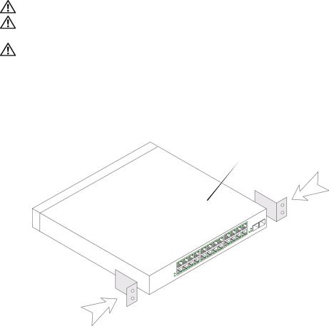
1Place the supplied rack-mounting bracket on one side of the device, ensuring that the mounting holes on the device line up to the mounting holes on the rack-mounting bracket.
The following figure illustrates where to mount the brackets.
Figure 1-1. Bracket Installation for Rack Mounting
 PowerConnect Switch
2Insert the supplied screws into the holes on the sides of the device and tighten with a screwdriver.
3Repeat the process for the rack-mounting bracket on the other side of the device.
4Insert the unit into the 48.26-cm (19-inch) rack, ensuring that the rack-mounting holes on the device line up to the mounting holes on the rack.
5Secure the unit to the rack with the rack screws (not provided). Fasten the lower pair of screws before the upper pair of screws. Ensure that the ventilation holes are not obstructed.
Getting Started Guide |
7 |
Installing on a Wall
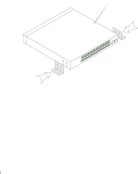
1Place the supplied wall-mounting bracket on one side of the device, ensuring that the mounting holes on the device line up to the mounting holes on the rack-mounting bracket.
The following figure illustrates where to mount the brackets.
Figure 1-2. Bracket Installation for Wall Mounting
 PowerConnect Switch
2Insert the supplied screws into the rack-mounting holes and tighten with a screwdriver.
3Repeat the process for the wall-mounting bracket on the other side of the device.
4Place the device against the wall and mark the wall through the bracket holes.
5Drill holes in the wall for the brackets and install the appropriate mounting hardware (not supplied).
6Place the device against the wall so that the bracket holes align with the holes in the wall.
7Insert and tighten the screws through each of the mounting brackets. Ensure that the ventilation holes are not obstructed.
8 Getting Started Guide
Figure 1-3. Mounting Device on Wall
Drilled Holes
Wall
Drilled Holes
Connecting a Device to a Power Supply
Connect the supplied AC power cable to the AC power connector on the back panel.
NOTE: Do not connect the power cable to a grounded AC outlet at this time. You will connect the device to a power source in the steps detailed in Starting and Configuring the Device.
Figure 1-4. Back-Panel Power Connectors
Power Connector
PowerConnect Switch Rear View
Connect the device to an AC outlet. After you have connected the device to a power source, confirm that the device is connected and operating correctly by examining the LEDs on the front panel.
Getting Started Guide |
9 |

Starting and Configuring the Device
NOTE: The device is designed to function as an unmanaged switch without any configuration of the management interface. Setup of the management interface is not a requirement if the switch is deployed as an unmanaged switch. To use the management functions, refer the configuration options and details in the User's Guide on the enclosed CD. Without specific configuration, the device functions with the default settings, as described in the User's Guide.
NOTE: Before proceeding, read the release notes for this product. You can download the release notes from the Dell Support website at support.dell.com.
NOTE: It is recommended that you obtain the most recent revision of the user documentation from the Dell Support website at support.dell.com.
Booting the Switch
When the device is connected to a power source, the device LEDs glow indicating that power is being supplied to the device. A power-on self-test (POST) runs every time the device is initialized and checks hardware components to determine if the device is fully operational before completely booting. If POST passes successfully, the System and the Power LEDs glow and a valid executable image is loaded into RAM.
The boot process runs approximately 90 seconds.
Initial Configuration
NOTE: The initial configuration uses the following assumptions:
•The PowerConnect device is configured with the pre configured default IP (192.168.2.1) and subnet mask (255.255.255.0).
•The PowerConnect device booted successfully.
To begin using the device, it is advisable to configure the device with the system specific configuration.
NOTE: Obtain the following information from the network administrator before configuring the device:
•The IP address to be assigned to the VLAN 1 interface through which the device is to be managed
•The IP subnet mask for the network
•The default gateway (next hop router) IP address for configuring the default route.
10 Getting Started Guide

To configure the device:
1Open the web management interface (from any desktop or workstation). To do so, enter the IP address of the device in the URL field of a web browser.
NOTE: The web management interface supports the following web browsers:
Microsoft Internet Explorer 6.x or above and Mozilla Version 1.7.x or above.
2 In the Web user interface, Click IP Addressing. The System IP Address window appears.
3Enter the IP Address, Subnet Mask and Default Gateway.
4Click Apply Changes. The device is configured.
NOTE: This getting started guide provides information on the steps necessary for basic setup of the switch. For more information on the management capabilities of the switch, please refer the PowerConnect 27xx Series User's Guide found on your documenatation CD.
Getting Started Guide |
11 |

12 Getting Started Guide
Systèmes Dell™ PowerConnect™ 27XX
Guide de mise en route
w w w . d e l l . c o m | s u p p o r t . d e l l . c o m

Remarques, avis et précautions
REMARQUE : une REMARQUE indique des informations importantes qui peuvent vous aider à mieux utiliser l'ordinateur.
AVIS : un AVIS vous avertit d'un dommage ou d'une perte de données potentiels et vous indique comment éviter ce problème.
 PRÉCAUTION : une PRÉCAUTION indique un risque potentiel d'endommagement du matériel, de blessure corporelle ou de mort.
____________________
Les informations contenues dans ce document peuvent être modifiées sans préavis. © 2004-2006 Dell Inc. Tous droits réservés.
La reproduction de ce document de quelque manière que ce soit sans l'autorisation écrite de Dell Inc. est strictement interdite.
Marques utilisées dans ce document : Dell, Dell OpenManage, PowerEdge, le logo DELL, Inspiron, Dell Precision, Dimension, OptiPlex, PowerConnect, PowerApp, PowerVault, Axim, DellNet et Latitude sont des marques de Dell Inc. ; Microsoft et Windows sont des marques déposées de Microsoft Corporation.
Tous les autres noms de marques et marques commerciales utilisés dans ce document se rapportent aux sociétés propriétaires des marques et des noms de ces produits. Dell Inc. décline tout intérêt dans l'utilisation des marques déposées et des noms de marques ne lui appartenant pas.
Modèles : PC2708, PC2716, PC2724 et PC2748
Novembre 2006 |
P/N T9020 |
Rev. A02 |
 Loading...