


 Loading...
Dell EMC PowerEdge C4140
Installation and Service Manual
Regulatory Model: E53S Series
Regulatory Type: E53S001
Notes, cautions, and warnings

 NOTE: A NOTE indicates important information that helps you make better use of your product.

 CAUTION: A CAUTION indicates either potential damage to hardware or loss of data and tells you how to avoid the problem.
 WARNING: A WARNING indicates a potential for property damage, personal injury, or death.
Copyright © 2017 Dell Inc. or its subsidiaries. All rights reserved. Dell, EMC, and other trademarks are trademarks of Dell Inc. or its subsidiaries. Other trademarks may be trademarks of their respective owners.
2017 - 12
Rev. A00

Contents
1 Product overview........................................................................................................................................... |
7 |
Front view and panel ......................................................................................................................................................... |
7 |
Back panel .......................................................................................................................................................................... |
9 |
Diagnostic indicators........................................................................................................................................................ |
10 |
NIC indicator codes..................................................................................................................................................... |
11 |
Power supply unit indicator codes............................................................................................................................. |
11 |
Locating Service Tag of your system............................................................................................................................. |
12 |
2 Documentation resources............................................................................................................................. |
14 |
3 Technical specifications................................................................................................................................ |
16 |
Chassis dimensions........................................................................................................................................................... |
17 |
Chassis weight.................................................................................................................................................................. |
17 |
GPU speci€cations........................................................................................................................................................... |
17 |
Processor speci€cations.................................................................................................................................................. |
18 |
PSU speci€cations............................................................................................................................................................ |
18 |
System battery speci€cations......................................................................................................................................... |
18 |
Expansion bus speci€cations........................................................................................................................................... |
18 |
Memory speci€cations..................................................................................................................................................... |
18 |
Storage speci€cations...................................................................................................................................................... |
19 |
Ports and connectors speci€cations.............................................................................................................................. |
19 |
VGA ports.................................................................................................................................................................... |
19 |
IDSDM or vFlash card............................................................................................................................................... |
20 |
Environmental speci€cations.......................................................................................................................................... |
20 |
Standard operating temperature............................................................................................................................... |
21 |
Particulate and gaseous contamination speci€cations.......................................................................................... |
22 |
4 Initial system setup and configuration.......................................................................................................... |
23 |
Setting up your system................................................................................................................................................... |
23 |
iDRAC con€guration........................................................................................................................................................ |
23 |
Options to set up iDRAC IP address........................................................................................................................ |
23 |
Log in to iDRAC.......................................................................................................................................................... |
23 |
Options to install the operating system......................................................................................................................... |
24 |
Methods to download €rmware and drivers........................................................................................................... |
24 |
Downloading drivers and €rmware.......................................................................................................................... |
25 |
5 Pre-operating system management applications.......................................................................................... |
26 |
Options to manage the pre-operating system applications........................................................................................ |
26 |
System Setup................................................................................................................................................................... |
26 |
Viewing System Setup.............................................................................................................................................. |
26 |
System Setup details................................................................................................................................................. |
27 |
System BIOS............................................................................................................................................................... |
27 |
Contents 3

iDRAC Settings utility................................................................................................................................................ |
48 |
Device Settings.......................................................................................................................................................... |
49 |
Dell Lifecycle Controller................................................................................................................................................... |
49 |
Embedded system management............................................................................................................................. |
49 |
Boot Manager................................................................................................................................................................... |
49 |
Viewing Boot Manager.............................................................................................................................................. |
49 |
Boot Manager main menu........................................................................................................................................ |
49 |
One-shot BIOS boot menu....................................................................................................................................... |
50 |
System Utilities.......................................................................................................................................................... |
50 |
PXE boot........................................................................................................................................................................... |
50 |
6 Installing and removing system components................................................................................................. |
51 |
Safety instructions............................................................................................................................................................ |
51 |
Before working inside your system................................................................................................................................. |
51 |
After working inside your system.................................................................................................................................... |
51 |
Recommended tools........................................................................................................................................................ |
52 |
System cover.................................................................................................................................................................... |
52 |
Removing the front system cover........................................................................................................................... |
52 |
Installing the front system cover.............................................................................................................................. |
53 |
Removing the rear system cover............................................................................................................................. |
54 |
Installing the rear system cover............................................................................................................................... |
55 |
Inside the system............................................................................................................................................................. |
56 |
Chassis intrusion switch.................................................................................................................................................. |
58 |
Removing the intrusion switch................................................................................................................................. |
58 |
Installing the intrusion switch................................................................................................................................... |
59 |
Air shroud.......................................................................................................................................................................... |
60 |
Removing the air shroud........................................................................................................................................... |
60 |
Installing the air shroud.............................................................................................................................................. |
61 |
System memory............................................................................................................................................................... |
62 |
General memory module installation guidelines...................................................................................................... |
63 |
Mode-speci€c guidelines.......................................................................................................................................... |
63 |
Removing a memory module.................................................................................................................................... |
64 |
Installing a memory module...................................................................................................................................... |
65 |
Processors and heat sinks.............................................................................................................................................. |
66 |
Removing a processor and heat sink module......................................................................................................... |
66 |
Removing the processor from the processor and heat sink module................................................................... |
67 |
Installing the processor into a processor and heat sink module........................................................................... |
69 |
Installing a processor and heat sink module............................................................................................................ |
71 |
Expansion cards and expansion card risers................................................................................................................... |
72 |
Expansion bus speci€cations.................................................................................................................................... |
72 |
Removing an expansion card riser........................................................................................................................... |
73 |
Installing an expansion card riser.............................................................................................................................. |
75 |
Removing an expansion card from the expansion card riser................................................................................ |
77 |
Installing an expansion card into expansion card riser........................................................................................... |
79 |
Optional IDSDM or vFlash module................................................................................................................................. |
80 |
Removing the MicroSD card..................................................................................................................................... |
81 |
4 Contents

Installing the MicroSD card........................................................................................................................................ |
81 |
Removing the IDSDM or vFlash module.................................................................................................................. |
81 |
Installing the IDSDM or vFlash module.................................................................................................................... |
82 |
Network daughter card................................................................................................................................................... |
83 |
Removing the network daughter card.................................................................................................................... |
83 |
Installing the network daughter card....................................................................................................................... |
84 |
System battery................................................................................................................................................................. |
85 |
Replacing the system battery................................................................................................................................... |
85 |
Optional internal USB memory key................................................................................................................................ |
86 |
Replacing the optional internal USB memory key.................................................................................................. |
86 |
Power supply units........................................................................................................................................................... |
87 |
Removing a power supply unit.................................................................................................................................. |
87 |
Installing a power supply unit.................................................................................................................................... |
88 |
System board................................................................................................................................................................... |
89 |
Removing the system board..................................................................................................................................... |
89 |
Installing the system board........................................................................................................................................ |
91 |
Trusted Platform Module................................................................................................................................................ |
94 |
Replacing the Trusted Platform Module................................................................................................................. |
94 |
Initializing TPM for BitLocker users......................................................................................................................... |
95 |
Initializing the TPM 1.2 for TXT users..................................................................................................................... |
95 |
Cooling fans...................................................................................................................................................................... |
95 |
Removing a cooling fan............................................................................................................................................. |
95 |
Installing a cooling fan............................................................................................................................................... |
96 |
Graphics processing unit................................................................................................................................................. |
97 |
PCIe Graphics processing unit........................................................................................................................................ |
97 |
GPU installation guidelines........................................................................................................................................ |
97 |
Removing a GPU riser cable from the system board............................................................................................ |
98 |
Removing a GPU........................................................................................................................................................ |
98 |
Removing a GPU riser cable board........................................................................................................................ |
100 |
Removing the custom GPU brackets from the GPUs removed from your system......................................... |
100 |
Removing the GPU brackets from the replacement GPUs................................................................................. |
101 |
Removing the optional GPU switch board ........................................................................................................... |
102 |
Installing the optional GPU switch board ............................................................................................................. |
103 |
Installing the custom GPU brackets on the replacement GPUs......................................................................... |
104 |
Installing the GPU brackets on the GPUs removed from your system............................................................. |
106 |
Installing a GPU riser cable board........................................................................................................................... |
107 |
Installing a GPU........................................................................................................................................................ |
108 |
Installing a GPU riser cable on the system board................................................................................................. |
109 |
GPU cabling diagrams............................................................................................................................................... |
111 |
SXM2 Graphics processing unit.................................................................................................................................... |
113 |
Removing the NVLink Air Shroud............................................................................................................................ |
114 |
Removing an SXM2-GPU Heat Sink....................................................................................................................... |
114 |
Removing an SXM2 GPU......................................................................................................................................... |
115 |
Removing the NVLink Board.................................................................................................................................... |
117 |
Installing the NVLink Board...................................................................................................................................... |
118 |
Contents 5

Installing an SXM2 GPU........................................................................................................................................... |
119 |
Installing an SXM2-GPU Heat Sink......................................................................................................................... |
121 |
Installing the NVLink Air Shroud............................................................................................................................. |
122 |
Control panel................................................................................................................................................................... |
123 |
Removing the control panel module....................................................................................................................... |
123 |
Installing the control panel module......................................................................................................................... |
124 |
7 Using system diagnostics........................................................................................................................... |
126 |
Dell Embedded System Diagnostics............................................................................................................................. |
126 |
Running the Embedded System Diagnostics from Boot Manager..................................................................... |
126 |
Running the Embedded System Diagnostics from the Dell Lifecycle Controller.............................................. |
126 |
System diagnostic controls...................................................................................................................................... |
127 |
8 Jumpers and connectors ........................................................................................................................... |
128 |
System board jumper settings...................................................................................................................................... |
128 |
System board jumpers and connectors....................................................................................................................... |
129 |
Disabling forgotten password........................................................................................................................................ |
130 |
9 Getting help............................................................................................................................................... |
132 |
Receiving automated support with SupportAssist .................................................................................................... |
132 |
Contacting Dell................................................................................................................................................................ |
132 |
Documentation feedback.............................................................................................................................................. |
133 |
Accessing system information by using QRL.............................................................................................................. |
133 |
Quick Resource Locator for C4140........................................................................................................................ |
133 |
6 Contents

1
Product overview
The PowerEdge C4140 is a 1U, 2-socket, incredibly dense purpose-built rack server that emphasizes performance and reliability in key areas such as virtualization, power, thermal, and systems management. With up to four double-width accelerators in just 1U of space, the C4140 delivers outstanding performance and maximum density while reducing space, cost and management requirements.
The system is designed to handle the most demanding technical computing workloads in €nancial services, life sciences, machine and deep learning, Oil & Gas exploration, and High Performance Computing (HPC). With Intel's Xeon platform and Nvidia's Volta technologies, C4140 €lls a key gap as a leading GPU-accelerated platform in the PowerEdge server portfolio to enable a scalable business architecture in a heterogeneous data center environment.
Figure 1. C4140 front view
Topics:
•Front view and panel
•Back panel
•Diagnostic indicators
•Locating Service Tag of your system
Front view and panel
Figure 2. Front view
1 Control panel
Product overview |
7 |
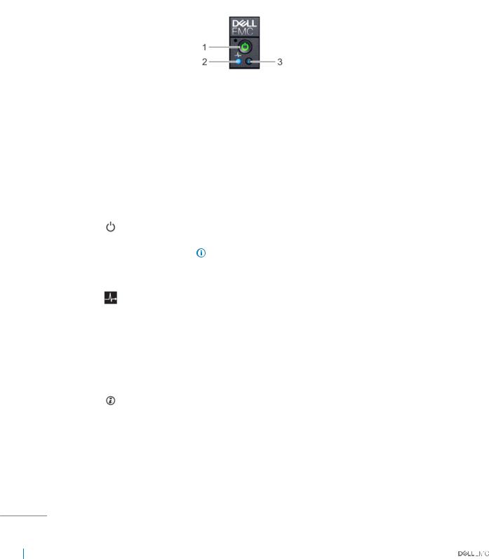
Table 1. Front view of the PowerEdge C4140 system.
Item |
Indicator, |
Description |
|
button, or |
|
|
connector |
|
|
|
|
1 |
Control panel |
Consists of the health indicator, power-on indicator, power button, and the system identi€cation |
|
|
button. |
|
|
|
Figure 3. Front panel
1 |
Power-on indicator/power button |
2 |
System-health indicator |
3 System identi€cation button
Table 2. Front panel features and indicators description of the PowerEdge C4140 system.
Item |
Indicator, |
Icon |
Description |
|
|
button, or |
|
|
|
|
connector |
|
|
|
|
|
|
|
|
1 |
Power-on |
|
The power-on indicator lights when the system power is on. The power button |
|
|
indicator, |
|
controls the power supply output to the system. |
|
|
power button |
|
|
NOTE: On ACPI-compliant operating systems, turning off the system |
|
|
|
||
|
|
|
|
|
|
|
|
|
using the power button causes the system to perform a graceful |
|
|
|
|
shutdown before power to the system is turned off. |
|
|
|
|
|
2 |
Health |
|
Indicates the health of the system. |
|
|
indicator |
|
• If the system is on and in good health, the indicator lights solid blue. No |
|
|
|
|
||
|
|
|
corrective action is required. |
|
|
|
|
• The indicator blinks amber if the system is on or in standby, and if any error |
|
|
|
|
exists (for example, a failed fan). See the System Event Log or system |
|
|
|
|
messages for the speci€c issue. For more information on error messages, see |
|
|
|
|
the Dell Event and Error Messages Reference Guide at Dell.com/esmmanuals. |
|
|
|
|
Invalid memory con€gurations can cause the system to halt at startup without |
|
|
|
|
any video output. See the Getting help section. |
|
|
|
|
|
|
3 |
System |
|
The identi€cation button on the front and back panels can be used to locate a |
|
|
identi€cation |
|
particular system within a rack. When one of these buttons is pressed, the |
|
|
button |
|
corresponding system identi€cation button on the back flashes until one of the |
|
|
|
|
buttons is pressed again. |
|
|
|
|
Press the system identi€cation button to turn the system ID on or off. |
|
If the system stops responding during POST, press and hold the system ID button for more than €ve seconds to enter BIOS progress mode.
To reset iDRAC (if not disabled in F2 iDRAC setup), press and hold the button for more than 15 seconds.
8 Product overview
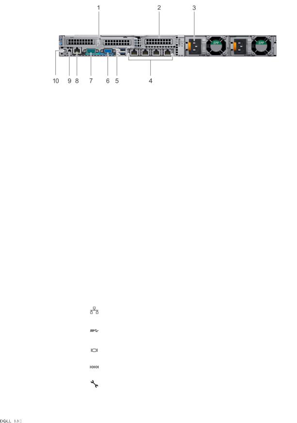
Back panel
Figure 4. Back panel
1PCIe expansion card slot 1 and 2
2PCIe expansion card slot 3
3Power supply unit (2)
4Ethernet connector (4)
5USB connector (2)
6Video connector
7Serial connector
8iDRAC Enterprise port
9NMI button
10System identi€cation button
Table 3. Back panel features and indicators description of the PowerEdge C4140 system
Item |
Indicator, |
Icon |
Description |
|
button or |
|
|
|
connector |
|
|
|
|
|
|
1 |
PCIe expansion |
|
Allows you to connect half height, low pro€le PCI Express expansion cards. |
|
card slot 1 and 2 |
|
|
|
|
|
|
2 |
PCIe expansion |
|
Allows you to connect half-height, low pro€le PCI Express expansion cards. |
|
card slot 3 |
|
|
|
|
|
|
3 |
Power supply |
|
Two 2400 W or 2000 W PSU. |
|
unit (2) |
|
|
|
|
|
|
4 |
Ethernet |
|
Four integrated 10/100/1000/Mbps NIC connectors. |
|
connector (4) |
|
|
|
|
|
|
5 |
USB connector |
|
Allows you to connect USB devices to the system. The ports are USB 3.0- |
|
(2) |
|
compliant. |
|
|
|
|
6 |
Video connector |
|
Allows you to connect a VGA display to the system. |
|
|
|
|
7 |
Serial connector |
|
Allows you to connect a serial device to the system. |
|
|
|
|
8 |
iDRAC |
|
Dedicated management port. |
|
Enterprise port |
|
|
|
|
|
|
Product overview |
9 |
Item |
Indicator, |
Icon |
Description |
|
button or |
|
|
|
connector |
|
|
|
|
|
|
9 |
NMI button |
|
Used to troubleshoot software and device driver errors when running certain |
|
|
|
operating systems. This button can be pressed using the end of a paper clip. |
|
|
|
Use this button only if directed to do so by quali€ed support personnel or by the |
|
|
|
operating system documentation. |
|
|
|
|
10 |
System |
|
The identi€cation button on the front and back panels can be used to locate a |
|
identi€cation |
|
particular system within a rack. When one of these buttons is pressed, the |
|
button |
|
corresponding system identi€cation button on the back flashes until one of the |
|
|
|
buttons is pressed again. |
|
|
|
Press the system identi€cation button to turn the system ID on or off. |
If the system stops responding during POST, press and hold the system ID button for more than €ve seconds to enter BIOS progress mode.
To reset iDRAC (if not disabled in F2 iDRAC setup), press and hold the button for more than 15 seconds.
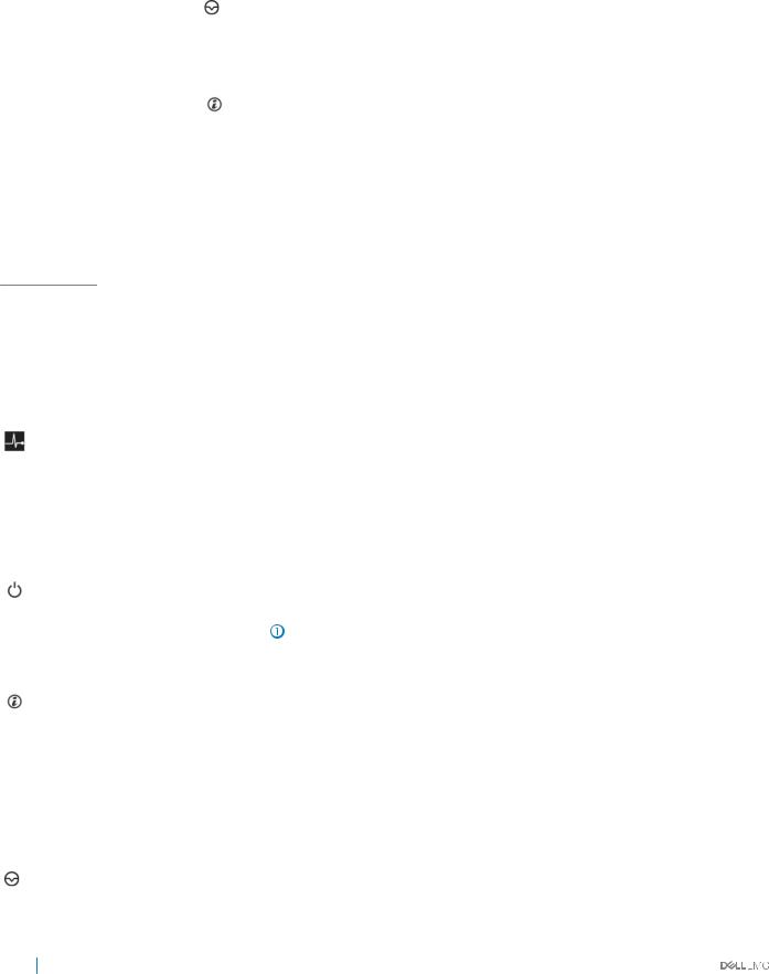
Diagnostic indicators
Table 4. Diagnostic Indicators |
|
|
|
Icon |
Indicator, button, |
Description |
|
|
or connector |
|
|
|
|
|
|
|
Health indicator |
Indicates the health of the system. |
|
|
|
• If the system is powered on and in good health, the indicator lights solid blue. No |
|
|
|
corrective action is required. |
|
|
|
• The indicator blinks amber if the system is on or in standby, and if any error exists (For |
|
|
|
example, a failed fan). See the System Event Log or system messages for the speci€c |
|
|
|
issue. For more information on error messages, see the Dell Event and Error Messages |
|
|
|
Reference Guide at Dell.com/OpenManageManuals. Invalid memory con€gurations |
|
|
|
can cause a blank screen or no video output. See the Getting help section. |
|
|
|
|
|
|
Power-on |
The power-on indicator lights when the system powered on. The power button controls |
|
|
indicator, power |
the power supply output to the system. |
|
|
button |
|
NOTE: On ACPI-compliant operating systems, turning off the system using the |
|
|
||
|
|
|
|
|
|
|
power button causes the system to perform a graceful shutdown before power |
|
|
|
to the system is turned off. |
|
|
|
|
|
System |
The identi€cation button on the front and back panels can be used to locate a particular |
|
|
identi€cation |
system within a rack. When one of these buttons is pressed, the corresponding system |
|
|
button |
identi€cation button on the back flashes until one of the buttons is pressed again. |
|
|
|
Press the system identi€cation button to turn the system ID on or off. |
|
|
|
If the system stops responding during POST, press and hold the system ID button for |
|
|
|
more than €ve seconds to enter BIOS progress mode. |
|
|
|
To reset iDRAC (if not disabled in F2 iDRAC setup), press and hold the button for more |
|
|
|
than 15 seconds. |
|
|
|
|
|
|
NMI button |
Used to troubleshoot software and device driver errors when running certain operating |
|
|
|
systems. Use a paper clip to press this button. |
|
|
|
|
|
10 Product overview
Icon |
Indicator, button, Description |
|
or connector |
|
|
|
Use this button only if directed to do so by quali€ed support personnel or by the operating |
|
system documentation. |
|
|
NIC indicator codes
The NIC on the back panel has an indicator that provides information about the network activity and link status. The activity LED indicates whether the NIC is currently connected or not. The link LED indicates the speed of the connected network.
Figure 5. NIC indicators |
|
|
|
|
1 |
link indicator |
|
2 |
activity indicator |
Table 5. NIC indicators |
|
|
|
|
Convention |
Status |
|
Condition |
|
|
|
|
|
|
A |
|
Link and activity indicators are off |
|
The NIC is not connected to the network. |
B |
|
Link indicator is green |
|
The NIC is connected to a valid network at its maximum |
|
|
|
|
port speed (1 Gbps or 10 Gbps). |
C |
|
Link indicator is amber |
|
The NIC is connected to a valid network at less than its |
|
|
|
|
maximum port speed. |
D |
|
Activity indicator is flashing green |
|
Network data is being sent or received. |
Power supply unit indicator codes
AC power supply units (PSUs) have an illuminated translucent handle that serves as an indicator. The indicator shows whether power is present or if a power fault has occurred.

 NOTE: The 2400 W and 2000 W PSUs use a C19 or C20 connector.
Product overview |
11 |
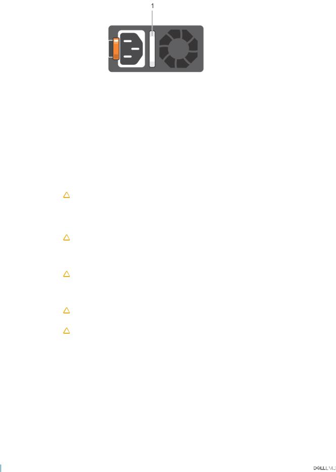
Figure 6. AC PSU status indicator
1 |
AC PSU status indicator/handle |
||
Table 6. AC PSU status indicator codes |
|||
Power indicator codes |
Condition |
||
|
|
||
Green |
A valid power source is connected to the PSU and the PSU is operational. |
||
Blinking amber |
Indicates a problem with the PSU. |
||
Not illuminated |
Power is not connected to the PSU. |
||
Blinking green |
When the €rmware of the PSU is being updated, the PSU handle blinks green. |
||
|
|
|
CAUTION: Do not disconnect the power cord or unplug the PSU when updating firmware. If |
|
|
|
|
|
|
|
firmware update is interrupted, the PSUs do not function. |
Blinking green and turns off |
When hot-plugging a PSU, the PSU handle blinks green €ve times at a rate of 4 Hz and turns off. This |
||
|
|
indicates a PSU mismatch with respect to efficiency, feature set, health status, or supported voltage. |
|
|
|
|
CAUTION: If two PSUs are installed, both the PSUs must have the same type of label; for |
|
|
|
|
|
|
|
example, Extended Power Performance (EPP) label. Mixing PSUs from previous generations of |
|
|
|
PowerEdge servers is not supported, even if the PSUs have the same power rating. This results |
|
|
|
in a PSU mismatch condition or failure to turn the system on. |
|
|
|
CAUTION: When correcting a PSU mismatch, replace only the PSU with the blinking indicator. |
|
|
|
|
|
|
|
Swapping the PSU to make a matched pair can result in an error condition and unexpected |
|
|
|
system shutdown. To change from a high output configuration to a low output configuration or |
|
|
|
vice versa, you must turn off the system. |
|
|
|
CAUTION: The 120 V AC PSU is not recommended for this system and using the same can cause |
|
|
|
|
|
|
|
system throttling. |
|
|
|
CAUTION: If two PSUs are used, they must be of the same type and have the same maximum |
|
|
|
|
|
|
|
output power. |
|
|
|
|
Locating Service Tag of your system
Your system is identi€ed by a unique Express Service Code and Service Tag number. The Express Service Code is and Service Tag are found on the back of the system by pulling out the information tag. Alternatively, the information may be on a sticker on the chassis of the system. This information is used by Dell EMC to route support calls to the appropriate personnel.
12 Product overview
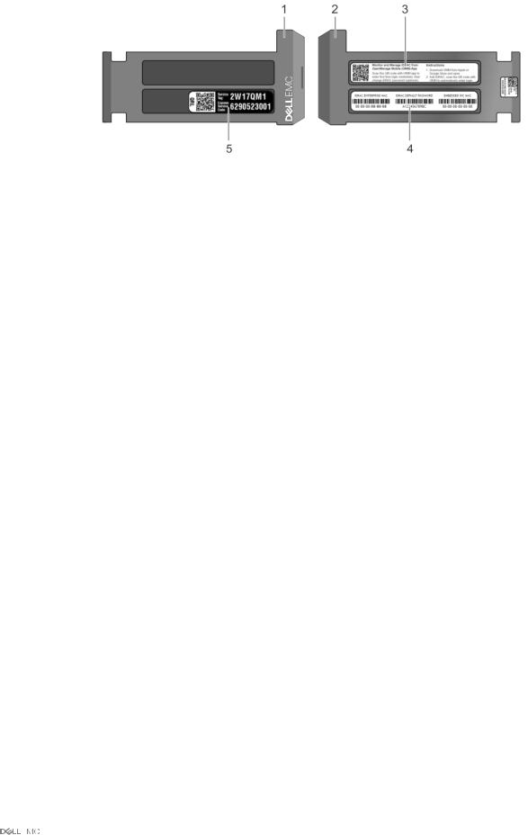
Figure 7. Locating Service Tag of your system |
|
|
|
1 |
Information tag (top view) |
2 |
Information tag (back view) |
3 |
OpenManage Mobile (OMM) label |
4 |
iDRAC MAC address and iDRAC secure password label |
5 |
Service Tag |
|
|
Product overview |
13 |

2
Documentation resources
This section provides information about the documentation resources for your system.
Table 7. Documentation resources for your system |
|
|
Task |
Document |
Location |
|
|
|
Setting up your system |
For more information about installing and securing |
Dell.com/poweredgemanuals |
|
the system into a rack, see the rack documentation |
|
|
included with your rack solution. |
|
|
For information about the technical speci€cations |
Dell.com/poweredgemanuals |
|
of your system, and turning on the system, see the |
|
|
Getting Started Guide document that is shipped |
|
|
with your system. |
|
Con€guring your system |
For information about the iDRAC features, |
Dell.com/idracmanuals |
|
con€guring and logging in to iDRAC, and managing |
|
|
your system remotely, see the Integrated Dell |
|
|
Remote Access Controller User's Guide. |
|
|
For information about installing the operating |
Dell.com/operatingsystemmanuals |
|
system, see the operating system documentation. |
|
|
For information about understanding Remote |
Dell.com/idracmanuals |
|
Access Controller Admin (RACADM) |
|
|
subcommands and supported RACADM interfaces, |
|
|
see the RACADM Command Line Reference Guide |
|
|
for iDRAC. |
|
|
For information about updating drivers and |
To download drivers: Dell.com/support/drivers |
|
€rmware, see the Methods to download €rmware |
|
|
and drivers section in this document. |
|
Managing your system |
For information about systems management |
Dell.com/openmanagemanuals |
|
software offered by Dell, see the Dell OpenManage |
|
|
Systems Management Overview Guide. |
|
|
For information about setting up, using, and |
Dell.com/openmanagemanuals |
|
troubleshooting OpenManage, see the Dell |
|
|
OpenManage Server Administrator User’s Guide. |
|
|
For information about installing, using, and |
Dell.com/openmanagemanuals |
|
troubleshooting Dell OpenManage Essentials, see |
|
|
the Dell OpenManage Essentials User’s Guide. |
|
|
For information about installing and using Dell |
Dell.com/serviceabilitytools |
|
SupportAssist, see the Dell EMC SupportAssist |
|
|
Enterprise User’s Guide. |
|
|
For understanding the features of Dell Lifecycle |
Dell.com/idracmanuals |
|
Controller, see the Dell Lifecycle Controller User’s |
|
|
Guide. |
|
14 Documentation resources

Task |
Document |
Location |
|
|
|
|
For information about partner programs enterprise |
Dell.com/openmanagemanuals |
|
systems management, see the OpenManage |
|
|
Connections Enterprise Systems Management |
|
|
documents. |
|
Working with the Dell |
For information about understanding the features |
Dell.com/storagecontrollermanuals |
PowerEdge RAID controllers |
of the Dell PowerEdge RAID controllers (PERC), |
|
|
Software RAID controllers, or BOSS card and |
|
|
deploying the cards, see the Storage controller |
|
|
documentation. |
|
Understanding event and error |
For information about checking the event and error |
Dell.com/openmanagemanuals > OpenManage |
messages |
messages generated by the system €rmware and |
software |
|
agents that monitor system components, see the |
|
|
Dell Event and Error Messages Reference Guide. |
|
Troubleshooting your system |
For information about identifying and |
Dell.com/poweredgemanuals |
|
troubleshooting the PowerEdge server issues, see |
|
|
the Server Troubleshooting Guide. |
|
Documentation resources |
15 |

3
Technical specifications
The technical and environmental speci€cations of your system are outlined in this section.
Topics:
•Chassis dimensions
•Chassis weight
•GPU speci€cations
•Processor speci€cations
•PSU speci€cations
•System battery speci€cations
•Expansion bus speci€cations
•Memory speci€cations
•Storage speci€cations
•Ports and connectors speci€cations
•Environmental speci€cations
16 Technical speci€cations
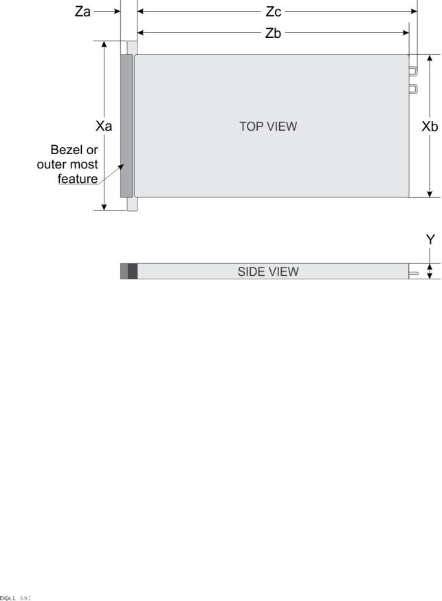
Chassis dimensions
Figure 8. Details the dimensions of PowerEdge C4140 system |
|
|
|
|||
Table 8. The dimensions of PowerEdge C4140 system |
|
|
|
|
||
Xa |
Xb |
Y |
Za with bezel |
Za without bezel |
Zb* |
Zc |
|
|
|
|
|
|
|
482.4 mm (18.99 |
434 mm (17.08 |
43.1 mm (1.69 |
18.0 mm (0.70 |
18.0 mm (0.70 |
886.4 mm (34.89 |
923.8 mm (36.37 |
inches) |
inches) |
inches) |
inches) |
inches) |
inches) |
inches) |
* - Zb goes to the nominal rear wall external surface where the system board I/O connectors are located.
Chassis weight
Table 9. Chassis weight |
|
|
System |
|
Maximum weight |
|
|
|
PowerEdge C4140 |
(with PCIe GPUs) |
22.1 kg (48.72 lb) |
PowerEdge C4140 |
(with SXM2 GPUs) |
24 kg (52.91 lb) |
GPU specifications
The PowerEdge C4140 supports up to 4 double wide GPUs, with 300 W each. The following GPUs are supported:
Technical speci€cations |
17 |

•NVIDIA Tesla P40
•NVIDIA Tesla P100 12 GB PCIe
•NVIDIA Tesla P100 16 GB PCIe and NVLink
•NVIDIA Tesla V100 16 GB PCIe and NVLink

 NOTE: The P100 and V100 GPUs must have PSU of dual 2400 W only.
Processor specifications
The PowerEdge C4140 system supports two Intel Xeon Processor Scalable Family processors.

 NOTE: Ensure that both the CPUs are populated and both are of same type or model.
PSU specifications
The PowerEdge C4140 system supports up to two AC power supply units (PSUs).
Table 10. PSU specifications |
|
|
|
|
|
PSU |
Class |
Heat dissipation |
Frequency |
Voltage |
Maximum input current |
|
|
(maximum) |
|
|
|
|
|
|
|
|
|
2400 W AC |
Platinum |
715 BTU/hr |
50/60 Hz |
200–240 V AC, autoranging |
14 - 16 A |
2000 W AC |
Platinum |
635 BTU/hr |
50/60 Hz |
200–240 V AC, autoranging |
11.5 A |
NOTE:
•All PSUs must be of same type or model and only redundant mode is supported.
•Heat dissipation is calculated using the PSU wattage rating.
•This system is also designed to connect to the IT power systems with a phase-to-phase voltage not exceeding 240 V.
System battery specifications
The PowerEdge C4140 system supports CR 2032 lithium coin cell system battery.
Expansion bus specifications
The PowerEdge C4140 system supports PCI express (PCIe) generation 3 expansion cards, which are installed on the system, using expansion card risers. This system supports two risers, riser 1A and riser 2A.
Memory specifications
Table 11. |
Memory specifications |
|
|
|
|
|||
DIMM type |
DIMM rank |
DIMM |
Single processor |
|
Dual processors |
|||
|
|
|
|
|||||
capacity |
Minimum RAM |
Maximum RAM |
Minimum RAM |
Maximum RAM |
||||
|
|
|
||||||
|
|
|
|
|||||
|
|
|
|
|
|
|
||
LRDIMM |
Quad rank |
64 GB |
64 GB |
768 GB |
128 GB |
1536 GB |
||
RDIMM |
|
Dual rank |
32 GB |
32 GB |
384 GB |
64 GB |
768 GB |
|
RDIMM |
|
Dual rank |
16 GB |
16 GB |
192 GB |
32 GB |
384 GB |
|
RDIMM |
|
Single rank |
8 GB |
8 GB |
96 GB |
16 GB |
192 GB |
|
18 Technical speci€cations

NOTE:
•Ensure that all the memory slots are populated either with DIMMs or DIMM blanks.
•It is recommended to have all DIMMs of same type.
Storage specifications
The PowerEdge C4140 system supports one BOSS PCIe card with M.2 SATA SSDs, and up to two NVMe/PCIe SSDs as internal storage.

 NOTE: The M.2 boot drives have to be of the same capacity and set in a mirrored RAID-1 configuration.
Ports and connectors specifications
Table 12. Ports and connectors specifications
Connectors
Back
NIC |
• Intel 10GbE Quad Port SFP+ (2+2) NDC |
|
|
||
|
• Intel 10GbE Quad Port (2+2) BT NDC |
|
|
• One RJ45 dedicated for iDRAC |
|
Serial |
9-pin, DTE, 16550-compatible |
|
USB |
Two 9-pin, USB 3.0-compliant |
|
Video |
15-pin VGA |
|
Internal |
|
|
USB |
One 9-pin, USB 3.0-compliant |
|
Internal dual SD module |
Two optional flash memory card slots with the internal dual SD |
|
|
module |
|
|
|
NOTE: Ensure that all SDs must be of same type or |
|
|
|
|
|
model. |
|
|
|
VGA ports
The Video Graphic Array (VGA) port enables you to connect the system to a VGA display. The PowerEdge C4140 system supports one 15pin VGA port on the back of system.
Video specifications
The PowerEdge C4140 system supports an integrated VGA controller.
Table 13. Supported video resolution options |
|
|
|
Resolution |
Refresh rate (Hz) |
Color depth (bit) |
|
|
|
|
|
640 X 480 |
60, |
70 |
8, 16, 32 |
800 X 600 |
60, |
75, 85 |
8, 16, 32 |
Technical speci€cations |
19 |

Resolution |
Refresh rate (Hz) |
Color depth (bit) |
|
|
|
|
|
1024 X 768 |
60, 75, 85 |
8, 16, 32 |
|
1152 X 864 |
60, 75, 85 |
8, 16, 32 |
|
1280 |
X 1024 |
60, 75 |
8, 16, 32 |
1440 |
X 900 |
60 |
8, 16, 32 |
1920 x 1200 |
60 |
8, 16, 32 |
|
IDSDM or vFlash card
The PowerEdge C4140 system supports Internal Dual SD module (IDSDM) and vFlash card. In the 14th generation of PowerEdge servers, IDSDM and vFlash card are combined into a single module, and are available in the following options:
•vFlash or
•vFlash and IDSDM
The IDSDM/vFlash card can be connected in a Dell-proprietary PCIe x1 slot using a USB 3.0 interface to host. IDSDM/vFlash module supports two MicroSD cards for IDSDM and one card for vFlash. The MicroSD card capacity for IDSDM are 16, 32, or 64 GB, while for vFlash the MicroSD card capacity is 16 GB.

 NOTE: There are two dip switches on the IDSDM/vFlash card for write-protection.

 NOTE: One IDSDM card slot is dedicated for redundancy.
NOTE: It is recommended to use Dell branded MicroSD cards associated with the IDSDM/vFlash configured systems.
Environmental specifications
NOTE: For additional information about environmental measurements for specific system configurations, see Dell.com/ environmental_datasheets.
Table 14. Temperature specifications |
|
Temperature |
Specifications |
|
|
Storage |
–40°C to 65°C (–40°F to 149°F) |
Continuous operation (for altitude less than 950 m or 3117 10°C to 30°C (50°F to 86°F) with no direct sunlight on the equipment. |
||
ft) |
|
NOTE: Certain system hardware configurations may require |
|
||
|
|
|
|
|
operating temperatures to be less than 25°C. For more |
|
|
information, see the Ambient temperature limitations section. |
|
|
|
Fresh air
Maximum temperature gradient (operating and storage)
For information about fresh air, see Expanded Operating Temperature section.
20°C/h (68°F/h)
20 Technical speci€cations
Table 15. Relative humidity specifications |
|
Relative humidity |
Specifications |
|
|
Storage |
5% to 95% RH with 33°C (91°F) maximum dew point. Atmosphere must be |
|
non-condensing at all times. |
Operating |
10% to 80% relative humidity with 29°C (84.2°F) maximum dew point. |
Table 16. Maximum vibration specifications |
|
Maximum vibration |
Specifications |
|
|
Operating |
0.26 Grms at 5 Hz to 350 Hz (all operation orientations). |
Storage |
1.88 Grms at 10 Hz to 500 Hz for 15 min (all six sides tested). |
Table 17. Maximum shock specifications |
|
Maximum shock |
Specifications |
|
|
Operating |
Six consecutively executed shock pulses in the positive and negative x, y, |
|
and z axes of 6 G for up to 11 ms. |
Storage |
Six consecutively executed shock pulses in the positive and negative x, y, |
|
and z axes (one pulse on each side of the system) of 71 G for up to 2 ms. |
Table 18. Maximum altitude specifications |
|
Maximum altitude |
Specifications |
|
|
Operating |
3048 m (10,000 ft) |
Storage |
12,000 m (39,370 ft) |
Table 19. Operating temperature de-rating specifications |
|
Operating temperature de-rating |
Specifications |
|
|
Up to 35°C (95°F) |
Maximum temperature is reduced by 1°C/300 m (1°F/547 ft) above 950 m |
|
(3,117 ft). |
35°C to 40°C (95°F to 104°F)
Maximum temperature is reduced by 1°C/175 m (1°F/319 ft) above 950 m (3,117 ft).
40°C to 45°C (104°F to 113°F)
Maximum temperature is reduced by 1°C/125 m (1°F/228 ft) above 950 m (3,117 ft).
Standard operating temperature
Table 20. Standard operating temperature specifications
Standard operating temperature |
Specifications |
Continuous operation (for altitude less than 950 m or 3117 10°C to 30°C (50°F to 86°F) with no direct sunlight on the equipment. ft)
Technical speci€cations |
21 |

Particulate and gaseous contamination specifications
The following table de€nes the limitations that help avoid any equipment damage or failure from particulate and gaseous contamination. If the levels of particulate or gaseous pollution exceed the speci€ed limitations and result in equipment damage or failure, you may need to rectify the environmental conditions. Remediation of environmental conditions is the responsibility of the customer.
Table 21. Particulate contamination specifications |
|
|
Particulate contamination |
Specifications |
|
|
|
|
Air €ltration |
Data center air €ltration as de€ned by ISO Class 8 per ISO 14644-1 with a |
|
|
95% upper con€dence limit. |
|
|
|
NOTE: This condition applies to data center environments only. Air |
|
|
|
|
|
filtration requirements do not apply to IT equipment designed to be |
|
|
used outside a data center, in environments such as an office or |
|
|
factory floor. |
|
|
|
|
|
NOTE: Air entering the data center must have the MERV11 or |
|
|
MERV13 filtration. |
Conductive dust |
Air must be free of conductive dust, zinc whiskers, or other conductive |
|
|
particles. |
|
|
|
NOTE: This condition applies to data center and non-data center |
|
|
|
|
|
environments. |
Corrosive dust |
• Air must be free of corrosive dust. |
|
|
||
•Residual dust present in the air must have a deliquescent point less than 60% relative humidity.
NOTE: This condition applies to data center and non-data center environments.
Table 22. Gaseous contamination specifications |
|
Gaseous contamination |
Specifications |
|
|
Copper coupon corrosion rate |
<300 Å/month per Class G1 as de€ned by ANSI/ISA71.04-1985. |
Silver coupon corrosion rate |
<200 Å/month as de€ned by AHSRAE TC9.9. |

 NOTE: Maximum corrosive contaminant levels measured at ≤50% relative humidity.
22 Technical speci€cations

4
Initial system setup and configuration
Setting up your system
Complete the following steps to set up your system:
1Unpack the system.
2Install the system into the rack. For more information about installing the system into the rack, see the Rail Installation Guide at Dell.com/poweredgemanuals.
3Connect the peripherals to the system.
4Connect the system to its electrical outlet.
5Turn the system on by pressing the power button or by using iDRAC.
6Turn on the attached peripherals.
For more information about setting up your system, see the Getting Started Guide that shipped with your system.
Related link
iDRAC con€guration
Options to set up iDRAC IP address
iDRAC configuration
The Integrated Dell Remote Access Controller (iDRAC) is designed to make system administrators more productive and improve the overall availability of Dell systems. iDRAC alerts administrators to system issues, helps them perform remote system management, and reduces the need for physical access to the system.
Options to set up iDRAC IP address
You must con€gure the initial network settings based on your network infrastructure to enable the communication to and from iDRAC.
You must use the default iDRAC IP address 192.168.0.120 to con€gure the initial network settings, including setting up DHCP or a static IP for iDRAC. You can set up the IP address by using one of the following interfaces:
Interfaces |
Document/Section |
iDRAC Settings |
See Dell Integrated Dell Remote Access Controller User's Guide at Dell.com/idracmanuals |
utility |
|
Dell Deployment |
See Dell Deployment Toolkit User’s Guide at Dell.com/openmanagemanuals |
Toolkit |
|
Dell Lifecycle |
See Dell Lifecycle Controller User’s Guide at Dell.com/idracmanuals |
Controller |
|
Log in to iDRAC
You can log in to iDRAC as:
Initial system setup and con€guration |
23 |

•iDRAC user
•Microsoft Active Directory user
•Lightweight Directory Access Protocol (LDAP) user
If you have opted for secure default access to iDRAC, the iDRAC secure default password is available on the back of the system Information tag. If you have not opted for secure default access to iDRAC, then the default user name and password are root and calvin. You can also log in by using Single Sign-On or Smart Card.

 NOTE: You must have the iDRAC credentials to log in to iDRAC.

 NOTE: Ensure that you change the default user name and password after setting up the iDRAC IP address.
For more information about logging in to the iDRAC and iDRAC licenses, see the latest Integrated Dell Remote Access Controller User's Guide at Dell.com/idracmanuals.
You can also access iDRAC by using RACADM. For more information, see the RACADM Command Line Interface Reference Guide at Dell.com/idracmanuals.
Options to install the operating system
If the system is shipped without an operating system, install the supported operating system by using one of the following resources:
Table 23. Resources to install the operating system |
|
Resources |
Location |
|
|
Systems Management Tools and Documentation media |
Dell.com/operatingsystemmanuals |
Lifecycle Controller |
Dell.com/idracmanuals |
OpenManage Deployment Toolkit |
Dell.com/openmanagemanuals |
Dell certi€ed VMware ESXi |
Dell.com/virtualizationsolutions |
Supported operating systems on PowerEdge systems |
Dell.com/ossupport |
Installation and How-to videos for supported operating systems on |
Supported Operating Systems for Dell PowerEdge Systems |
PowerEdge systems |
|
Methods to download firmware and drivers
You can download the €rmware and drivers by using any of the following methods:
Table 24. Firmware and drivers |
|
Methods |
Location |
|
|
From the Dell Support site |
Dell.com/support/home |
Using Dell Remote Access Controller Lifecycle Controller (iDRAC |
Dell.com/idracmanuals |
with LC) |
|
Using Dell Repository Manager (DRM) |
Dell.com/openmanagemanuals |
Using Dell OpenManage Essentials (OME) |
Dell.com/openmanagemanuals |
Using Dell Server Update Utility (SUU) |
Dell.com/openmanagemanuals |
Using Dell OpenManage Deployment Toolkit (DTK) |
Dell.com/openmanagemanuals |
24 Initial system setup and con€guration

Downloading drivers and firmware
Dell recommends that you download and install the latest BIOS, drivers, and systems management €rmware on your system.
Prerequisite
Ensure that you clear the web browser cache before downloading the drivers and €rmware.
Steps
1Go to Dell.com/support/drivers.
2In the Drivers & Downloads section, type the Service Tag of your system in the Enter a Service Tag or product ID box, and then click
Submit.
NOTE: If you do not have the Service Tag, select Detect Product to allow the system to automatically detect your Service Tag, or click View products, and navigate to your product.
3Click Drivers & Downloads.
The drivers that are applicable to your selection are displayed.
4Download the drivers to a USB drive, CD, or DVD.
Initial system setup and con€guration |
25 |

5
Pre-operating system management applications
You can manage basic settings and features of a system without booting to the operating system by using the system €rmware.
Topics:
•Options to manage the pre-operating system applications
•System Setup
•Dell Lifecycle Controller
•Boot Manager
•PXE boot
Options to manage the pre-operating system applications
Your system has the following options to manage the pre-operating system applications:
•System Setup
•Dell Lifecycle Controller
•Boot Manager
•Preboot Execution Environment (PXE)
System Setup
By using the System Setup screen, you can con€gure the BIOS settings, iDRAC settings, and device settings of your system.
NOTE: Help text for the selected field is displayed in the graphical browser by default. To view the help text in the text browser, press F1.
You can access system setup by using two methods:
•Standard graphical browser—The browser is enabled by default.
•Text browser—The browser is enabled by using Console Redirection.
Viewing System Setup
To view the System Setup screen, perform the following steps:
1Turn on, or restart your system.
2Press F2 immediately after you see the following message:
F2 = System Setup
NOTE: If your operating system begins to load before you press F2, wait for the system to finish booting, and then restart your system and try again.
26 Pre-operating system management applications

System Setup details
The System Setup Main Menu screen details are explained as follows:
Option Description
System BIOS |
Enables you to con€gure BIOS settings. |
iDRAC Settings Enables you to con€gure the iDRAC settings.
The iDRAC settings utility is an interface to set up and con€gure the iDRAC parameters by using UEFI (Uni€ed Extensible Firmware Interface). You can enable or disable various iDRAC parameters by using the iDRAC settings utility. For more information about this utility, see Integrated Dell Remote Access Controller User’s Guide at Dell.com/idracmanuals.
Device Settings Enables you to con€gure device settings.
System BIOS
You can use the System BIOS screen to edit speci€c functions such as boot order, system password, setup password, set the SATA and PCIe NVMeRAID mode, and enable or disable USB ports.
Viewing System BIOS
To view the System BIOS screen, perform the following steps:
1Turn on, or restart your system.
2Press F2 immediately after you see the following message:
F2 = System Setup
NOTE: If your operating system begins to load before you press F2, wait for the system to finish booting, and then restart your system and try again.
3 On the System Setup Main Menu screen, click System BIOS.
System BIOS Settings details
The System BIOS Settings screen details are explained as follows:
Option Description
System Information Speci€es information about the system such as the system model name, BIOS version, and Service Tag.
Memory Settings Speci€es information and options related to the installed memory.
Processor Settings Speci€es information and options related to the processor such as speed and cache size.
NVMe Settings Speci€es options to change the NVMe settings. If the system contains the NVMe drives that you want to con€gure in a RAID array, you must set both this €eld and the Embedded SATA €eld on the SATA Settings menu to RAID mode. You might also need to change the Boot Mode setting to UEFI. Otherwise, you should set this €eld to Non-RAID mode.
Boot Settings |
Speci€es options to specify the Boot mode (BIOS or UEFI). Enables you to modify UEFI and BIOS boot settings. |
Network Settings Speci€es options to manage the UEFI network settings and boot protocols.
Pre-operating system management applications |
27 |

Option Description
Legacy network settings are managed from the Device Settings menu.
Integrated Devices Speci€es options to manage integrated device controllers and ports, speci€es related features and options.
Serial Speci€es options to manage the serial ports, its related features and options.
Communication
System Profile Speci€es options to change the processor power management settings, memory frequency.
Settings
System Security Speci€es options to con€gure the system security settings, such as system password, setup password, Trusted Platform Module (TPM) security, and UEFI secure boot. It also manages the power button on the system.
Redundant OS Speci€es the options to con€gure the Redundant OS settings.
Settings
Miscellaneous Speci€es options to change the system date and time.
Settings
System Information
You can use the System Information screen to view system properties such as Service Tag, system model name, and the BIOS version.
Viewing System Information
To view the System Information screen, perform the following steps:
1Turn on, or restart your system.
2Press F2 immediately after you see the following message:
F2 = System Setup
NOTE: If your operating system begins to load before you press F2, wait for the system to finish booting, and then restart your system and try again.
3On the System Setup Main Menu screen, click System BIOS.
4On the System BIOS screen, click System Information.
System Information details
The System Information screen details are explained as follows:
Option |
Description |
System Model |
Speci€es the system model name. |
Name |
|
System BIOS |
Speci€es the BIOS version installed on the system. |
Version |
|
System |
Speci€es the current version of the Management Engine €rmware. |
Management |
|
Engine Version |
|
System Service Tag Speci€es the system Service Tag.
System Speci€es the name of the system manufacturer.
Manufacturer
28 Pre-operating system management applications

Option |
Description |
System |
Speci€es the contact information of the system manufacturer. |
Manufacturer |
|
Contact |
|
Information |
|
System CPLD |
Speci€es the current version of the system complex programmable logic device (CPLD) €rmware. |
Version |
|
UEFI Compliance |
Speci€es the UEFI compliance level of the system €rmware. |
Version |
|
Memory Settings
You can use the Memory Settings screen to view all the memory settings and enable or disable speci€c memory functions, such as system memory testing and node interleaving.
Viewing Memory Settings
To view the Memory Settings screen, perform the following steps:
1Turn on, or restart your system.
2Press F2 immediately after you see the following message:
F2 = System Setup
NOTE: If your operating system begins to load before you press F2, wait for the system to finish booting, and then restart your system and try again.
3On the System Setup Main Menu screen, click System BIOS.
4On the System BIOS screen, click Memory Settings.
Memory Settings details
The Memory Settings screen details are explained as follows:
Option |
Description |
|
System Memory |
Speci€es the memory size in the system. |
|
Size |
|
|
System Memory |
Speci€es the type of memory installed in the system. |
|
Type |
|
|
System Memory |
Speci€es the system memory speed. |
|
Speed |
|
|
System Memory |
Speci€es the system memory voltage. |
|
Voltage |
|
|
Video Memory |
Speci€es the amount of video memory. |
|
System Memory |
Speci€es whether the system memory tests are run during system boot. Options are Enabled and Disabled. This |
|
Testing |
option is set to Disabled by default. |
|
Memory Operating |
Speci€es the memory operating mode. The options available are Optimizer Mode, Single Rank Spare Mode, Multi |
|
Mode |
Rank Spare Mode, Mirror Mode, and Dell Fault Resilient Mode. This option is set to Optimizer Mode by default. |
|
|
|
NOTE: The Memory Operating Mode option can have different default and available options based on |
|
|
|
|
|
the memory configuration of your system. |
Pre-operating system management applications |
29 |

Option Description
NOTE: The Dell Fault Resilient Mode option establishes an area of memory that is fault resilient. This mode can be used by an operating system that supports the feature to load critical applications or enables the operating system kernel to maximize system availability.
Current State of Speci€es the current state of the memory operating mode.
Memory Operating
Mode
Node Interleaving Speci€es if Non-Uniform Memory Architecture (NUMA) is supported. If this €eld is set to Enabled, memory interleaving is supported if a symmetric memory con€guration is installed. If the €eld is set to Disabled, the system supports NUMA (asymmetric) memory con€gurations. This option is set to Disabled by default.
Processor Settings
You can use the Processor Settings screen to view the processor settings, and perform speci€c functions such as enabling virtualization technology, hardware prefetcher, logical processor idling, and opportunistic self-refresh.
Viewing Processor Settings
To view the Processor Settings screen, perform the following steps:
1Turn on, or restart your system.
2Press F2 immediately after you see the following message:
F2 = System Setup
NOTE: If your operating system begins to load before you press F2, wait for the system to finish booting, and then restart your system and try again.
3On the System Setup Main Menu screen, click System BIOS.
4On the System BIOS screen, click Processor Settings.
Processor Settings details
The Processor Settings screen details are explained as follows:
Option |
Description |
Logical Processor |
Enables or disables the logical processors and displays the number of logical processors. If this option is set to |
|
|
|
Enabled, the BIOS displays all the logical processors. If this option is set to Disabled, the BIOS displays only one |
|
logical processor per core. This option is set to Enabled by default. |
Virtualization |
Enables or disables the virtualization technology for the processor. This option is set to Enabled by default. |
Technology |
|
Adjacent Cache |
Optimizes the system for applications that need high utilization of sequential memory access. This option is set to |
Line Prefetch |
Enabled by default. You can disable this option for applications that need high utilization of random memory |
|
access. |
Hardware |
Enables or disables the hardware prefetcher. This option is set to Enabled by default. |
Prefetcher |
|
DCU Streamer |
Enables or disables the Data Cache Unit (DCU) streamer prefetcher. This option is set to Enabled by default. |
Prefetcher |
|
DCU IP Prefetcher |
Enables or disables the Data Cache Unit (DCU) IP prefetcher. This option is set to Enabled by default. |
30 Pre-operating system management applications
Loading...