


Dell™ Dimension™ 1100/B110 Systems Service Manual
Before You Begin
Removing the Computer Cover
Technical Overview
Technical Specifications
Advanced Troubleshooting
System Setup
Removing and Installing Parts
Replacing the Computer Cover
Notes, Notices, and Cautions
NOTE: A NOTE indicates important information that helps you make better use of your computer.
NOTICE: A NOTICE indicates either potential damage to hardware or loss of data and tells you how to avoid the problem.
CAUTION: A CAUTION indicates a potential for property damage, personal injury, or death.
Abbreviations and Acronyms
For a complete list of abbreviations and acronyms, see the Dell Dimension Help file.
If you purchased a Dell™ n Series computer, any references in this document to Microsoft® Windows® operating systems are not applicable.
Information in this document is subject to change without notice. © 2006 Dell Inc. All rights reserved.
Reproduction in any manner whatsoever without the written permission of Dell Inc. is strictly forbidden.
Trademarks used in this text: Dell, the DELL logo, Inspiron, Dell Precision, Dimension, OptiPlex, Latitude, PowerEdge, PowerVault, PowerApp, and Dell OpenManage are trademarks of Dell Inc.; Intel, Pentium, and Celeron are registered trademarks of Intel Corporation; Microsoft and Windows are registered trademarks of Microsoft Corporation.
Other trademarks and trade names may be used in this document to refer to either the entities claiming the marks and names or their products. Dell Inc. disclaims any proprietary interest in trademarks and trade names other than its own.
Model DMC August 2006 Rev. A02

Back to Contents Page
Before You Begin
Dell™ Dimension™ 1100/B110 Systems Service Manual
 Getting Started
 Recommended Tools
 Turning Off Your Computer
 Before Working Inside Your Computer
Getting Started
This chapter provides procedures for removing and installing the components in your computer. Unless otherwise noted, each procedure assumes that the following conditions exist:
 You have performed the steps in Turning Off Your Computer and Before Working Inside Your Computer.
 You have read the safety information in your Dell™ Product Information Guide.
 A component can be replaced or—if purchased separately—installed by performing the removal procedure in reverse order.
Recommended Tools
The procedures in this document may require the following tools:
 Small flat-blade screwdriver
 Phillips screwdriver
Turning Off Your Computer
NOTICE: To avoid losing data, save and close any open files and exit any open programs before you turn off your computer.
1.Shut down the operating system:
a.Save and close any open files, exit any open programs, click the Start button, and then click Turn Off Computer.
b.In the Turn off computer window, click Turn off.
The computer turns off after the operating system shutdown process finishes.
2.Ensure that the computer and any attached devices are turned off. If your computer and attached devices did not automatically turn off when you shut down your operating system, press and hold the power button for 4 seconds.
Before Working Inside Your Computer

Use the following safety guidelines to help protect your computer from potential damage and to help ensure your own personal safety.
CAUTION: Before you begin any of the procedures in this section, follow the safety instructions located in the Product Information Guide.
CAUTION: Handle components and cards with care. Do not touch the components or contacts on a card. Hold a card by its edges or by its metal mounting bracket. Hold a component such as a processor by its edges, not by its pins.
NOTICE: Only a certified service technician should perform repairs on your computer. Damage due to servicing that is not authorized by Dell is not covered by your warranty.
NOTICE: When you disconnect a cable, pull on its connector or on its strain-relief loop, not on the cable itself. Some cables have a connector with locking tabs; if you are disconnecting this type of cable, press in on the locking tabs before you disconnect the cable. As you pull connectors apart, keep them evenly aligned to avoid bending any connector pins. Also, before you connect a cable, ensure that both connectors are correctly oriented and aligned.
NOTICE: To avoid damaging the computer, perform the following steps before you begin working inside the computer.
1. Turn off your computer.
NOTICE: To disconnect a network cable, first unplug the cable from your computer and then unplug it from the network wall jack.
2.Disconnect any telephone or telecommunication lines from the computer.
3.Disconnect your computer and all attached devices from their electrical outlets, and then press the power button to ground the system board.
CAUTION: To guard against electrical shock, always unplug your computer from the electrical outlet before opening the cover.
4. Open the computer cover.
NOTICE: Before touching anything inside your computer, ground yourself by touching an unpainted metal surface, such as the metal at the back of the computer. While you work, periodically touch an unpainted metal surface to dissipate any static electricity that could harm internal components.
Back to Contents Page

Back to Contents Page
Removing the Computer Cover
Dell™ Dimension™ 1100/B110 Systems Service Manual
CAUTION: Before you begin any of the procedures in this section, follow the safety instructions located in the Product Information Guide.
CAUTION: To guard against electrical shock, always unplug your computer from the electrical outlet before opening the cover.
1.Follow the procedures in Before You Begin.
2.Lay your computer on its side with the computer cover facing up.
3.If your computer cover has a cover latch, slide and hold the cover latch.
4.Grip the indents on the computer cover, and slide the computer cover toward the back of the computer.
5. Place the computer cover on a level surface.
Back to Contents Page
Back to Contents Page
Technical Overview
Dell™ Dimension™ 1100/B110 Systems Service Manual
 Inside View of Your Computer
 System Board Components
 Power Supply DC Connector Pin Assignments
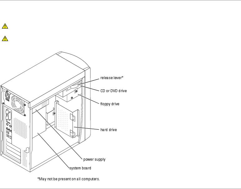
Inside View of Your Computer
CAUTION: Before you begin any of the procedures in this section, see the safety instructions located in the
Product Information Guide.
CAUTION: To guard against electrical shock, always unplug your computer from the electrical outlet before opening the computer cover.
System Board Components

Power Supply DC Connector Pin Assignments
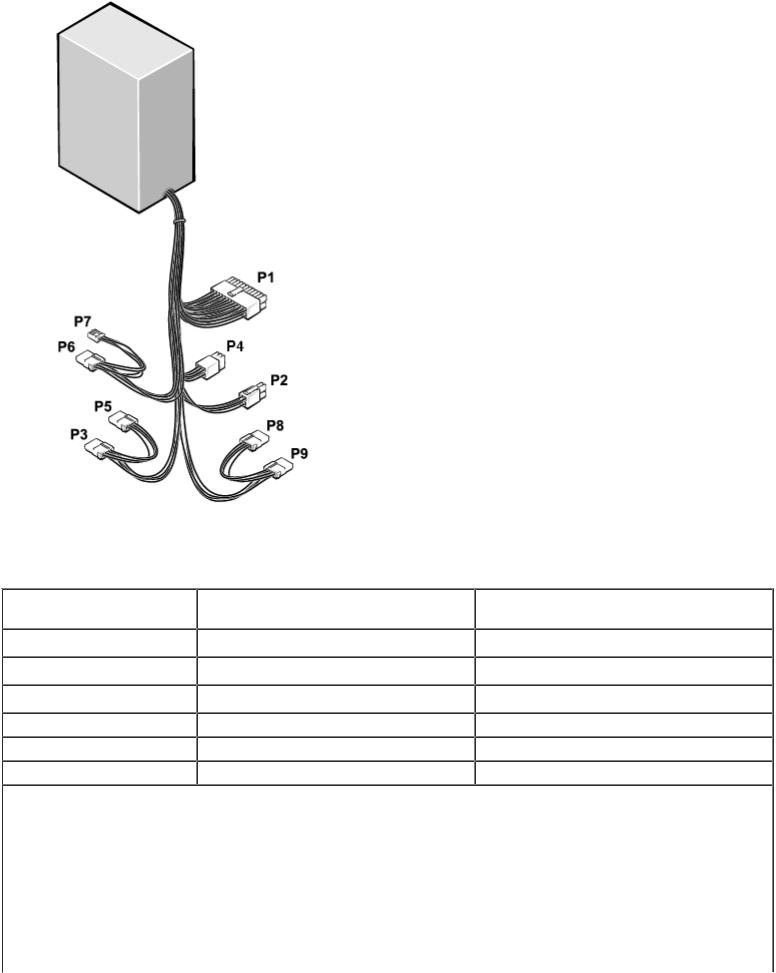
The 250-W power supply can operate from an AC power source of 115 VAC or 230 VAC at 50 – 60 Hz. The power supply provides the DC operating voltages and currents listed in the following table.
Output Voltage1 |
Minimum Current (A) |
Maximum Current (A)2 |
+12 VDC |
0.0 |
16.03 |
+5 VDC |
1.0/0.24 |
22.0 |
+3.3 VDC |
0.1/0.05 |
18.0 |
- |
- |
- |
–12 VDC |
0.0 |
1.0 |
+5 VFP |
0.0 |
2.0 |
1Outputs will meet and not exceed SELV requirements per electrical standards, i.e. UL 60950, IEC 60950, EN60950 PAR.2.3.
2Maximum continuous combined load on +5 VDC and +3.3 VDC outputs will not exceed 150 watts.
3Peak +12 VDC output power (up to 17.0 amps) will not exceed 15 seconds in duration. Under this condition, tolerance on the +12v output, is allowed to be +/- 10%.
4+5 VDC minimum load will be 0.2A when there is a minimum load of 0.3A on the +12 VDC and 0.42A on the +3.3 VDC outputs simultaneously. +5V min load is 1A for load transient tests.
5In system applications where +3.3VDC is not used, all other outputs will stay within regulation while the +3.3 VDC output

 is in a zero load condition.
DC Power Connector P1
NOTE: The +3.3 VDC output wires (orange) must be 16 AWG. All other output wires must be 18 AWG.
 Pin Number
  Signal name
  Wire Color
1 |
+3.3 VDC |
Orange |
|
2 |
+3.3 VDC |
Orange |
|
3 |
COM |
Black |
|
4 |
+5 |
VDC |
Red |
5 |
COM |
Black |
|
6 |
+5 |
VDC |
Red |
7 |
COM |
Black |
|
8 |
POK |
Gray |
|
9 |
+5 |
VFP |
Purple |
10 |
+12 VDC |
Yellow |
|
11 |
+3.3 VDC |
Orange |
|
12 |
–12 VDC |
Blue |
|
13 |
COM |
Black |
|
14 |
PS_ON |
Green |
|
15 |
COM |
Black |
|
16 |
COM |
Black |
|
17 |
COM |
Black |
|
18 |
N/C |
N/C |
|
19 |
+5 |
VDC |
Red |
20 |
+5 |
VDC |
Red |
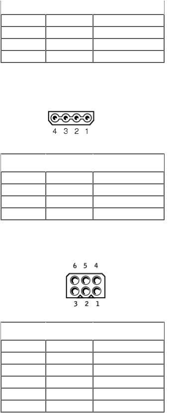
DC Power Connector P2
 Pin Number
  Signal Name
  18-AWG Wire Color
1 |
COM |
Black |
2 |
COM |
Black |
3 |
+12 VDC |
Yellow |
4 |
+12 VDC |
Yellow |
DC Power Connectors P8 and P9
 Pin Number
  Signal Name
  18-AWG Wire Color
1 |
+12 VDC |
Yellow |
2 |
COM |
Black |
3 |
COM |
Black |
4 |
+5 VDC |
Red |
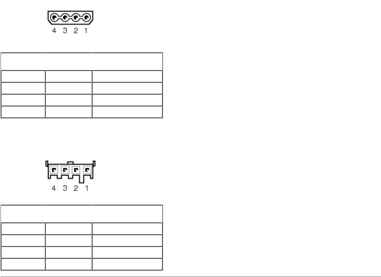
DC Power Connector P4
 Pin Number
  Signal Name
  18-AWG Wire Color
1 |
- |
No connect |
2 |
COM |
Black |
3 |
COM |
Black |
4 |
+3.3 VDC |
Orange |
5 |
+5 VDC |
Red |
6 |
+12 VDC |
Yellow |
DC Power Connector P6
 Pin Number
  Signal Name
  18-AWG Wire Color
1 |
+12 VDC |
Yellow |
2 |
COM |
Black |
3 |
COM |
Black |
4 |
+5 VDC |
Red |
DC Power Connector P7
 Pin Number
  Signal Name
  22-AWG Wire Color
1 |
+5 VDC |
Red |
2 |
COM |
Black |
3 |
COM |
Black |
4 |
+12 VDC |
Yellow |
Back to Contents Page
Back to Contents Page
Technical Specifications
Dell™ Dimension™ 1100/B110 Systems Service Manual
 Processor
Processor type
 Level 1 (L1) cache Level 2 (L2) cache
Intel® Pentium® 4 with HT Technology and Intel Celeron®
NOTE: Not all Pentium 4 processors support Hyper-Threading technology.
 8 KB
8 KB
128-KB or 512-KB (depending on your computer configuration) pipelined-burst, eight-way set associative, write-back SRAM
Memory |
|
Type |
333and 400-MHz DDR SDRAM |
|
NOTE: DDR333 and DDR400 memory |
|
runs at 266MHz when configured with |
|
Celeron 400MHz FSB processors |
|
NOTE: DDR333 memory runs at 320MHz |
|
when configured with Pentium 4 800MHz |
|
FSB processors |
Memory connectors |
two |
Memory capacities |
128-, 256-, 512-, or 1-GB non-ECC |
Minimum memory |
128 MB |
|
NOTE: Between 1 and 64 MB of system |
|
memory may be allocated to support |
|
graphics, depending on system memory |
|
size and other factors. |
Maximum memory |
2 GB |
BIOS address |
F0000h |
Computer Information |
|
Chip set |
Intel 865 GV |
DMA channels |
Seven |
Interrupt levels |
24 |
BIOS chip (NVRAM) |
4 Mb |
NIC |
integrated network interface capable of |
|
10/100 communication. |
System Clock |
Intel Pentium 4: 800 MHz |

|
Intel Celeron: 533 MHz |
Video |
|
Type |
Integrated Intel Extreme Graphics 2 |
Audio |
|
Type |
AC97, Sound Blaster Emulation, ADI 1980 |
|
audio controller with 2.1 implementation |
Expansion Bus |
|
Bus type |
PCI |
Bus speed |
33 MHz |
PCI |
|
connectors |
three |
connector size |
120 pins |
connector data width (maximum) |
32 bits |
Drives |
|
Externally accessible: |
|
|
One bay for a floppy drive, and two bays |
|
for CD/DVD drives |
Available devices |
Floppy drive, USB memory devices, CD |
|
drive, |
|
CD-RW drive, DVD drive, DVD-RW drive, |
|
and DVD and CD-RW combo drive |
Internally accessible: |
|
|
One bay for 1-inch-high IDE hard drives |
Connectors |
|
External connectors: |
|
Serial |
9-pin connector; 16550C-compatible |
Parallel |
25-hole connector (bidirectional) |
Video |
15-hole connector |
Network adapter |
RJ45 connector |
PS/2 (keyboard and mouse) |
6-pin mini-DIN |
USB |
two front-panel and four back-panel USB |
|
2.0–compliant connectors |
Audio |
Three connectors for line-in, line-out, and |
|
microphone; one front-panel connector |
|
for headphones |
System board connectors: |
|
Primary IDE drive |
40-pin connector on PCI local bus |
Secondary IDE drive
Floppy drive
CD Audio
Fan
 Controls and Lights
Power control
 Hard-drive access light
Link integrity light (on integrated network adapter)
Activity light (on integrated network adapter)
 Diagnostic lights
 Power
Power
DC power supply:
Wattage
Heat dissipation
Voltage (see the safety instructions located in the Product Information Guide for important voltage setting information)
 40-pin connector on PCI local bus
34-pin connector
 4-pin connector 3-pin connector
 Push button
Green
No light for 10-Mb operation; green light for 100-Mb operation
 Yellow blinking light
Four lights on the back panel
 250 W
250 W
853 BTU/hr
NOTE: Heat dissipation is calculated based upon the power supply wattage rating.
manual selection power supplies — 90 to 135 V at 50/60 Hz; 180 to 265 V at 50/60 Hz
Backup battery |
3-V CR2032 lithium coin cell |
Physical |
|
Height x width x depth |
41.9 x 18.1 x 36.8 cm |
|
(16.5 x 7.13 x 14.50 inches) |
Weight |
11.34 kg (25 lb) |
Environmental |
|
Temperature: |
|
Operating |
10º to 30ºC (50º to 86ºF) |
|
NOTE: At 30°C (86°F), the maximum |
|
operating altitude is 914 m (3000 ft). |
Storage |
–40º to 65ºC (–40º to 149ºF) |
Relative humidity |
20% to 80% (noncondensing) |
Maximum vibration: |
|
Operating |
0.25 G at 3 to 200 Hz at 0.5 octave/min |
Storage |
2.20 Grms at 10 to 500 Hz at 1 |
|
octave/min |

Maximum shock: |
|
Operating |
105 G, 2 ms |
Storage |
32 G with a velocity change of 596.9 |
|
cm/sec (235 inches/sec) |
Altitude: |
|
Operating |
–15.2 to 3048 m (–50 to 10,000 ft) |
|
NOTE: At 30°C (95°F), the maximum |
|
operating altitude is 914 m (3000 ft). |
Storage |
–15.2 to 10,670 m (–50 to 35,000 ft) |
|
|
Back to Contents Page |
|

Back to Contents Page
Advanced Troubleshooting
Dell™ Dimension™ 1100/B110 Systems Service Manual
 Power Lights
 Network Lights
 Diagnostic Lights
 Beep Codes
 System Messages
Power Lights
The power button light located on the front of your computer illuminates and blinks or remains solid to indicate different states:
 If the power light is green, the power status is good and the computer is functioning properly.
 If the power light is green and the computer is not responding, see Network Lights.
 If the power light is blinking green, the computer is in standby mode. Press a key on the keyboard or move the mouse to resume normal operation.
 If the power light is off, the computer is either turned off or is not receiving power.
 Reseat the power cable into both the power connector on the back of the computer and the electrical outlet.
 If the computer is plugged into a power strip, ensure that the power strip is plugged into an electrical outlet and that the power strip is turned on. Also bypass power protection devices, power strips, and power extension cables to verify that the computer turns on properly.
 Ensure that the electrical outlet is working by testing it with another device, such as a lamp.
 Ensure that the main power cable and front panel cable are securely connected to the system board.
 If the power light is blinking amber, the computer is receiving electrical power, but an internal power problem might exist.
 Ensure that the voltage selection switch is set to match the AC power at your location (if applicable).
 Ensure that the processor power cable is securely connected to the system board.
 If the power light is steady amber, a device might be malfunctioning or incorrectly installed.
 Remove and then reinstall the memory modules.
 Remove and then reinstall any cards.
 Remove and then reinstall the graphics card, if applicable.
Network Lights
|
100 Mb Link |
|
10 Mb Link |
No Link |
Active |
Non-active |
Active |
Non-active |
|
blinking |
on |
blinking |
on |
off |

Yellow LED |
|
|
|
|
|
|
|
on |
on |
off |
off |
off |
|
Green LEG |
|
|
|
|
|
|
|
|
|
|
|
|
|
Diagnostic Lights
CAUTION: Before you begin any of the procedures in this section, follow the safety instructions located in the Product Information Guide.
To help you troubleshoot a problem, your computer has four lights labeled "A," "B," "C," and "D" on the back panel. The lights can be yellow or green. When the computer starts normally, the lights flash. After the computer starts, all four lights display solid green. If the computer malfunctions, the color and sequence of the lights identify the problem.
Light Pattern |
Problem Description |
The computer is in a normal off condition or a possible pre-BIOS failure has occurred.
Memory modules are detected, but a memory failure has occurred.
Suggested Resolution
Plug the computer into a working electrical outlet and press the power button.
If you have one memory module installed, reinstall the memory module and restart the computer.
 If you have two or more memory modules installed, remove the modules, reinstall one memory module, and then restart the computer. If the computer starts normally, reinstall an additional module. Continue until you have identified a faulty module or reinstalled all modules without error.
 If available, install properly working memory of the same type into your computer.
 If the problem persists, see "Contacting Dell" in your Owner's Manual for instructions on obtaining technical assistance.
A possible graphics |
If the computer has a graphics card, remove the card, reinstall it, and |
card failure has |
then restart the computer. |
occurred. |
If the problem still exists, install a graphics card that you know works |
|
and restart the computer. |
|
If the problem persists or the computer has integrated graphics, see |
|
"Contacting Dell" in your Owner's Manual for instructions on obtaining |
|
technical assistance. |
A possible floppy or |
Reseat all power and data cables and restart the computer. |
hard drive failure has |
|
occurred. |
|
A possible USB failure |
Reinstall all USB devices, check cable connections, and then restart the |
has occurred. |
computer. |
Memory modules are |
Ensure that no special memory module/memory connector placement |
detected, but a |
requirements exist (see Specifications). |
memory configuration |
Verify that the memory modules that you are installing are compatible |
or compatibility error |
with your computer (see Specifications). |
exists. |
If the problem persists, see "Contacting Dell" in your Owner's Manual for |
|
instructions on obtaining technical assistance. |
A possible expansion |
1. Determine if a conflict exists by removing a card (not a graphics card) |
card failure has |
and restarting the computer. |

occurred. |
|
2. If the problem persists, reinstall the card that you removed, remove a |
|
|
different card, and then restart the computer. |
|
|
3. Repeat this process for each card. If the computer starts normally, |
|
|
troubleshoot the last card removed from the computer for resource |
|
|
conflicts. |
|
|
4. If the problem persists, see "Contacting Dell" in your Owner's Manual for |
|
|
instructions on obtaining technical assistance. |
Another failure has |
|
Ensure that the cables are properly connected to the system board from |
|
||
occurred. |
|
the hard drive, CD drive, and DVD drive. |
|
|
If there is an error message on your screen identifying a problem with a |
|
|
device (such as the floppy drive or hard drive), check the device to |
|
|
make sure it is functioning properly. |
|
|
The operating system is attempting to boot from a device (such as the |
|
|
floppy drive or hard drive); check system setup to make sure that the |
|
|
boot sequence is correct for the devices installed on your computer. |
|
|
If the problem persists, see "Contacting Dell" in your Owner's Manual for |
|
|
instructions on obtaining technical assistance. |
The computer is in a |
|
None. |
normal operating |
|
|
condition after POST. |
|
|
Beep Codes
Your computer might emit a series of beeps during start-up if the monitor cannot display errors or problems. This series of beeps, called a beep code, identifies a problem. One possible beep code (code 1-3-1) consists of one beep, a burst of three beeps, and then one beep. This beep code tells you that the computer encountered a memory problem.
Reseating the memory modules may fix the beep code errors in the following table. If the problem persists, see "Contacting Dell" in your Owner's Manual for instructions on obtaining technical assistance.
 Code
Code  Cause
Cause
1-3-1 through 2-4-4 Memory not being properly identified or used
 4-3-1
4-3-1  Memory failure above address 0FFFFh
If you hear one of the following beep codes, see "Contacting Dell" in your Owner's Manual for instructions on obtaining technical assistance.
 Code
Code  Cause
Cause
1-1-2 Microprocessor register failure
 1-1-3
1-1-3  NVRAM
NVRAM
1-1-4 ROM BIOS checksum failure
 1-2-1
1-2-1  Programmable interval timer
1-2-2 DMA initialization failure
1-2-3 DMA page register read/write failure
 Loading...