


Brocade G620
Table of contents
 Loading...
53-1003990-01
16 December 2015
Brocade G620
Hardware Installation Guide

©
2015, Brocade Communications Systems, Inc. All Rights Reserved.
ADX, Brocade, Brocade Assurance, the B-wing symbol, DCX, Fabric OS, HyperEdge, ICX, MLX, MyBrocade, OpenScript, The Effortless
Network, VCS, VDX, Vplane, and Vyatta are registered trademarks, and Fabric Vision and vADX are trademarks of Brocade
Communications Systems, Inc., in the United States and/or in other countries. Other brands, products, or service names mentioned may be
trademarks of others.
Notice: This document is for informational purposes only and does not set forth any warranty, expressed or implied, concerning any
equipment, equipment feature, or service offered or to be offered by Brocade. Brocade reserves the right to make changes to this document
at any time, without notice, and assumes no responsibility for its use. This informational document describes features that may not be
currently available. Contact a Brocade sales office for information on feature and product availability. Export of technical data contained in
this document may require an export license from the United States government.
The authors and Brocade Communications Systems, Inc. assume no liability or responsibility to any person or entity with respect to the
accuracy of this document or any loss, cost, liability, or damages arising from the information contained herein or the computer programs that
accompany it.
The product described by this document may contain open source software covered by the GNU General Public License or other open
source license agreements. To find out which open source software is included in Brocade products, view the licensing terms applicable to
the open source software, and obtain a copy of the programming source code, please visit http://www.brocade.com/support/oscd.

Contents
Preface.....................................................................................................................................7
Document conventions......................................................................................7
Text formatting conventions.................................................................. 7
Command syntax conventions.............................................................. 7
Notes, cautions, and warnings.............................................................. 8
Brocade resources............................................................................................ 9
Contacting Brocade Technical Support.............................................................9
Document feedback........................................................................................ 10
About This Document.............................................................................................................. 11
Supported hardware and software.................................................................. 11
What's new in this document...........................................................................11
Device Overview......................................................................................................................13
Hardware features...........................................................................................13
License options............................................................................................... 14
Port-side view..................................................................................................14
Nonport-side view........................................................................................... 15
Device management options...........................................................................15
Preparing for Installation.........................................................................................................17
Safety precautions.......................................................................................... 17
General precautions............................................................................17
ESD precautions................................................................................. 18
Power precautions.............................................................................. 18
Lifting and weight-related precautions................................................ 19
Laser precautions................................................................................20
Facility requirements....................................................................................... 20
Quick installation checklist.............................................................................. 21
Shipping carton contents.................................................................................23
Mounting the Device............................................................................................................... 25
Mounting options.............................................................................................25
Precautions specific to mounting.................................................................... 25
Standalone installation ................................................................................... 26
Installing the Universal Four-Post Rack Kit (XBR-R000296).......................... 26
Installation requirements..................................................................... 27
Time and items required..................................................................... 28
Flush-front mounting........................................................................... 30
Flush-rear (recessed) mounting.......................................................... 35
Installing the Universal Two-Post Rack kit (XBR-R000294)........................... 40
Installation requirements..................................................................... 41
Time and items required..................................................................... 41
Flush-front mounting........................................................................... 42
Mid-mounting...................................................................................... 46
Brocade G620 Hardware Installation Guide
3
53-1003990-01

Initial Setup and Verification.................................................................................................51
Items required............................................................................................... 51
Providing power to the device.......................................................................51
Establishing a first-time serial connection.....................................................52
Configuring the IP address............................................................................53
Using DHCP to set the IP address....................................................53
Setting a static IP address................................................................ 53
Setting the date and time.............................................................................. 53
Setting the time zone........................................................................ 54
Synchronizing local time with an external source............................. 55
Customizing the chassis name and switch name......................................... 55
Establishing an Ethernet connection.............................................................56
Setting the domain ID....................................................................................56
Verifying correct operation............................................................................ 56
Backing up the configuration.........................................................................57
Powering down the device............................................................................ 58
Installing Transceivers and Cables.........................................................................................59
Time and items required............................................................................... 59
Precautions specific to transceivers and cables........................................... 60
Cleaning the fiber-optic connectors.............................................................. 60
Managing cables...........................................................................................60
Installing an SFP+ transceiver...................................................................... 61
Replacing an SFP+ transceiver.................................................................... 62
Installing a QSFP transceiver........................................................................63
Replacing a QSFP transceiver......................................................................64
Verifying the operation of new transceivers.................................................. 65
Monitoring the Device........................................................................................................... 67
Interpreting port-side LEDs........................................................................... 67
System power LED........................................................................... 67
System status LED............................................................................68
FC port status LED............................................................................69
QSFP port status LED.......................................................................69
Interpreting nonport-side LEDs..................................................................... 70
Power supply and fan assembly status LED.....................................71
Interpreting the POST results........................................................................71
Interpreting the BOOT results....................................................................... 72
Running diagnostic tests...............................................................................72
Power Supply and Fan Assembly............................................................................................75
Power supply and fan assembly overview.................................................... 75
Precautions specific to the power supply and fan assemblies......................76
Identifying the airflow direction......................................................................77
Power supply and fan assembly status LED.................................................78
Power supply and fan assembly unit fault indicators.................................... 78
Power supply and fan assembly task guide..................................................78
Time and items required............................................................................... 79
Recording power supply and fan assembly critical information.................... 79
Removing a power supply and fan assembly............................................... 80
Inserting a new power supply and fan assembly.......................................... 81
Verifying the operation of the power supply and fan assemblies..................82
4
Brocade G620 Hardware Installation Guide
53-1003990-01

Brocade G620 Technical Specifications.................................................................................. 83
Regulatory Statements............................................................................................................91
BSMI statement (Taiwan)................................................................................91
Canadian requirements...................................................................................91
CE statement.................................................................................................. 91
China CC statement........................................................................................92
China ROHS................................................................................................... 93
FCC warning (US only)................................................................................... 93
Germany statement.........................................................................................93
KCC statement (Republic of Korea)................................................................93
VCCI statement...............................................................................................93
Cautions and Danger Notices.................................................................................................. 95
Danger Notices............................................................................................... 95
Cautions.......................................................................................................... 98
Brocade G620 Hardware Installation Guide 5
53-1003990-01

6 Brocade G620 Hardware Installation Guide
53-1003990-01

Preface
● Document conventions......................................................................................................7
● Brocade resources............................................................................................................ 9
● Contacting Brocade Technical Support.............................................................................9
● Document feedback........................................................................................................ 10
Document conventions
The document conventions describe text formatting conventions, command syntax conventions, and
important notice formats used in Brocade technical documentation.
Text formatting conventions
Text formatting conventions such as boldface, italic, or Courier font may be used in the flow of the text
to highlight specific words or phrases.
Format
Description
bold text
Identifies command names
Identifies keywords and operands
Identifies the names of user-manipulated GUI elements
Identifies text to enter at the GUI
italic text
Identifies emphasis
Identifies variables
Identifies document titles
Courier font
Identifies CLI output
Identifies command syntax examples
Command syntax conventions
Bold and italic text identify command syntax components. Delimiters and operators define groupings of
parameters and their logical relationships.
Convention
Description
bold text Identifies command names, keywords, and command options.
italic text Identifies a variable.
value In Fibre Channel products, a fixed value provided as input to a command
option is printed in plain text, for example, --show WWN.
Brocade G620 Hardware Installation Guide 7
53-1003990-01

Convention Description
[ ] Syntax components displayed within square brackets are optional.
Default responses to system prompts are enclosed in square brackets.
{ x | y | z } A choice of required parameters is enclosed in curly brackets separated by
vertical bars. You must select one of the options.
In Fibre Channel products, square brackets may be used instead for this
purpose.
x | y A vertical bar separates mutually exclusive elements.
< > Nonprinting characters, for example, passwords, are enclosed in angle
brackets.
...
Repeat the previous element, for example, member[member...].
\
Indicates a “soft” line break in command examples. If a backslash separates
two lines of a command input, enter the entire command at the prompt without
the backslash.
Notes, cautions, and warnings
Notes, cautions, and warning statements may be used in this document. They are listed in the order of
increasing severity of potential hazards.
NOTE
A Note provides a tip, guidance, or advice, emphasizes important information, or provides a reference
to related information.
ATTENTION
An Attention statement indicates a stronger note, for example, to alert you when traffic might be
interrupted or the device might reboot.
CAUTION
A Caution statement alerts you to situations that can be potentially hazardous to you or cause
damage to hardware, firmware, software, or data.
DANGER
A Danger statement indicates conditions or situations that can be potentially lethal or
extremely hazardous to you. Safety labels are also attached directly to products to warn of
these conditions or situations.
Notes, cautions, and warnings
8 Brocade G620 Hardware Installation Guide
53-1003990-01

Brocade resources
Visit the Brocade website to locate related documentation for your product and additional Brocade
resources.
You can download additional publications supporting your product at www.brocade.com. Select the
Brocade Products tab to locate your product, then click the Brocade product name or image to open the
individual product page. The user manuals are available in the resources module at the bottom of the
page under the Documentation category.
To get up-to-the-minute information on Brocade products and resources, go to MyBrocade. You can
register at no cost to obtain a user ID and password.
Release notes are available on MyBrocade under Product Downloads.
White papers, online demonstrations, and data sheets are available through the Brocade website.
Contacting Brocade Technical Support
As a Brocade customer, you can contact Brocade Technical Support 24x7 online, by telephone, or by e-
mail. Brocade OEM customers contact their OEM/Solutions provider.
Brocade customers
For product support information and the latest information on contacting the Technical Assistance
Center, go to http://www.brocade.com/services-support/index.html.
If you have purchased Brocade product support directly from Brocade, use one of the following methods
to contact the Brocade Technical Assistance Center 24x7.
Online Telephone E-mail
Preferred method of contact for non-
urgent issues:
• My Cases through MyBrocade
• Software downloads and licensing
tools
• Knowledge Base
Required for Sev 1-Critical and Sev
2-High issues:
• Continental US: 1-800-752-8061
• Europe, Middle East, Africa, and
Asia Pacific: +800-AT FIBREE
(+800 28 34 27 33)
• For areas unable to access toll
free number: +1-408-333-6061
• Toll-free numbers are available in
many countries.
support@brocade.com
Please include:
• Problem summary
• Serial number
• Installation details
• Environment description
Brocade OEM customers
If you have purchased Brocade product support from a Brocade OEM/Solution Provider, contact your
OEM/Solution Provider for all of your product support needs.
• OEM/Solution Providers are trained and certified by Brocade to support Brocade
®
products.
• Brocade provides backline support for issues that cannot be resolved by the OEM/Solution Provider.
Brocade resources
Brocade G620 Hardware Installation Guide 9
53-1003990-01

• Brocade Supplemental Support augments your existing OEM support contract, providing direct
access to Brocade expertise. For more information, contact Brocade or your OEM.
• For questions regarding service levels and response times, contact your OEM/Solution Provider.
Document feedback
To send feedback and report errors in the documentation you can use the feedback form posted with
the document or you can e-mail the documentation team.
Quality is our first concern at Brocade and we have made every effort to ensure the accuracy and
completeness of this document. However, if you find an error or an omission, or you think that a topic
needs further development, we want to hear from you. You can provide feedback in two ways:
• Through the online feedback form in the HTML documents posted on www.brocade.com.
• By sending your feedback to documentation@brocade.com.
Provide the publication title, part number, and as much detail as possible, including the topic heading
and page number if applicable, as well as your suggestions for improvement.
Document feedback
10 Brocade G620 Hardware Installation Guide
53-1003990-01

About This Document
● Supported hardware and software.................................................................................. 11
● What's new in this document...........................................................................................11
Supported hardware and software
The following tables list the power supply and fan assemblies, and rack mount kits supported on the
Brocade G620 FC switch running Fabric OS 8.0.0 or later.
Power supply and fan assembliesTABLE 1
Part number Description Introduced (OS) Currently
supported (OS)
XBR-G250WPSAC-F 250W AC power supply with nonport-side
exhaust airflow
Fabric OS 8.0.0 Yes
XBR-G250WPSAC-R 250W AC power supply with nonport-side
intake airflow
Fabric OS 8.0.0 Yes
Rack mount kitsTABLE 2
Part number Description
XBR-R000294 Universal two-post mid-mount or flush-mount rack kit
XBR-R000296 Universal four-post fixed rack mount kit
What's new in this document
This is a new document.
Brocade G620 Hardware Installation Guide
11
53-1003990-01

What's new in this document
12 Brocade G620 Hardware Installation Guide
53-1003990-01

Device Overview
● Hardware features...........................................................................................................13
● License options............................................................................................................... 14
● Port-side view..................................................................................................................14
● Nonport-side view........................................................................................................... 15
● Device management options...........................................................................................15
Hardware features
The Brocade G620 offers the following features and capabilities:
• Up to 48 auto-sensing ports supporting high-performance 32-Gbps SFP+ ports technology in a single
domain.
• Up to four 128-Gbps (4 x 32-Gbps) QSFP ports to connect to the QSFP ports of another Brocade
G620 device.
• Dynamic Ports on Demand (Dynamic-POD) scaling from a base configuration of 24 ports to 64 ports
(two 12-port SFP+ PODs and one 16-port QSFP POD).
• 4-, 8-, 16-, and 32-Gbps auto-sensing Fibre Channel switch and router ports.
‐ A 32-Gbps optical transceiver can auto-negotiate to 32 Gbps, 16 Gbps, or 8 Gbps.
‐ A 16-Gbps optical transceiver can auto-negotiate to 16 Gbps, 8 Gbps, or 4 Gbps.
NOTE
The port speed is determined by the maximum speed supported by the optical transceiver at the
other end of the link.
• 10-Gbps manually set capability on FC ports (requires the optional 10-Gigabit FCIP/Fibre Channel
license).
‐ 10-Gbps performance is enabled by 10-Gbps SFP+ transceivers.
‐ Ports can be configured for 10-Gbps for metro connectivity.
• Universal ports self-configure as a E_Ports, F_Ports, M_Ports, or D_Ports. EX_Ports can be
activated on a per-port basis with the optional Integrated Routing license.
‐ A Diagnostic Port (D_Port) provides diagnostics, troubleshooting, and verification services for the
physical media.
• Support for port-side exhaust or nonport-side exhaust airflow for cooling.
• Brocade small form-factor pluggable plus (SFP+) optical transceivers support any combination of
Short Wavelength (SWL), Long Wavelength (LWL) or Extended Long Wavelength (ELWL) optical
media among the switch ports.
• Extended distance Fibre Channel to support long distance native FC connectivity.
• 10-Gbps Fibre Channel integration on any selected port provides DWDM metro connectivity on the
same switch.
• Port-to-port latency is minimized to 700 nanoseconds by using cut-through frame switching at 32
Gbps.
• High performance T1022 processor with two cores operating at 1.2 GHz delivers high performance,
scalability, and advanced Fabric Vision functionality.
Brocade G620 Hardware Installation Guide
13
53-1003990-01
• One 10BASE-T / 100BASE-TX / 1000BASE-T RJ45 connector Ethernet port for management
connection. In conjunction with EZSwitchSetup, this port supports switch IP address discovery and
configuration, eliminating the need to attach a serial cable to configure the switch IP address.
• One RS-232 3-wire (Tx, Rx, and Gnd) universal asynchronous receiver/transmitter (UART) serial
port to BMC with RJ-45 connector for debugging initial switch setup (if not using EZSwitch Setup)
and factory default restoration. Integral LEDs remain unlit at all times.
• One internal e-USB module provides 2 GB of persistent storage, increased serviceability, and error
logging functionality by facilitating easier firmware upgrades and downloads of the system log files.
• One external USB connector.
• Two hot-swappable redundant integrated power supply and fan assembly field-replaceable units.
• 48 hot-pluggable SFP+ optical transceiver slots and 4 hot-pluggable QSFP optical transceiver slots.
• 64 bicolor (green/amber) LEDs to indicate the status for each port.
• One green LED to indicate valid system power.
• One bicolor (green/amber) LED to indicate the system status.
• Two Ethernet LEDs: one bicolor (green/amber) LED to indicate link at 1000/100/10 Mbps and one
green LED to indicate activity.
• SEEPROM for switch identification.
• Real-time power monitoring.
• Real-time voltage monitoring.
• Real-time fan monitoring including airflow direction.
• Real-time digital thermometers for temperature monitoring.
• Real-time clock (RTC) with battery.
License options
The Brocade G620 uses a capacity-based Ports on Demand (POD) license method. Refer to the
Brocade Fabric OS Software Licensing Guide for more details.
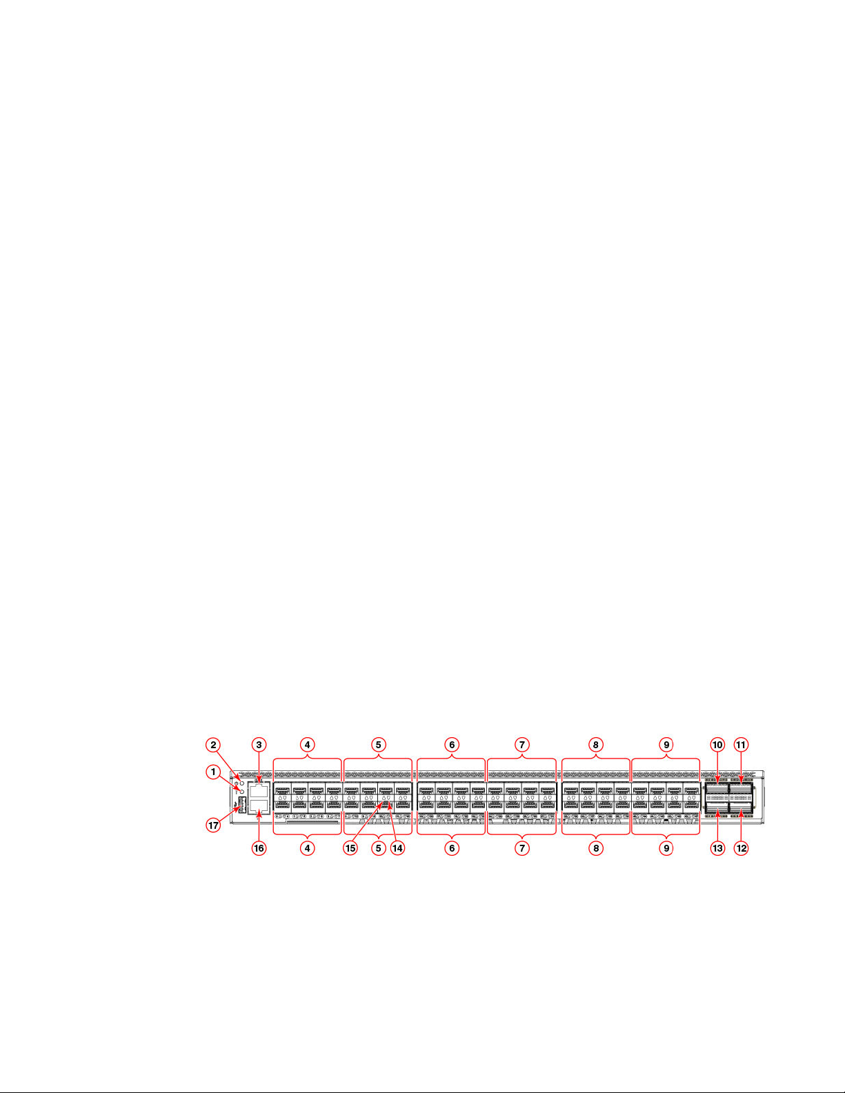
Port-side view
The following illustration shows the port-side view of the Brocade G620 Fibre Channel switch.
1 System status LED
2 System power LED
3 UART RJ-45 serial console port
4 SFP+ FC (four upper and four lower)
ports 0-7
5 SFP+ FC (four upper and four lower)
ports 8-15
6 SFP+ FC (four upper and four lower)
ports 16-23
7 SFP+ FC (four upper and four lower)
ports 24-31
License options
14 Brocade G620 Hardware Installation Guide
53-1003990-01
8 SFP+ FC (four upper and four lower)
ports 32-39
9 SFP+ FC (four upper and four lower)
ports 40-47
10 QSFP port 0 (FC ports 48-51)
11 QSFP port 2 (FC ports 56-59)
12 QSFP port 3 (FC ports 60-63)
13 QSFP port 1 (FC ports 52-55)
14 SFP+ (lower) port 14 status LED
15 SFP+ (upper) port 10 status LED
16 1000Base-T/100Base-TX/10Base-T
RJ-45 Ethernet management port
17 USB port
FIGURE 1 Port-side view
NOTE
All the ports are connected to a single ASIC.
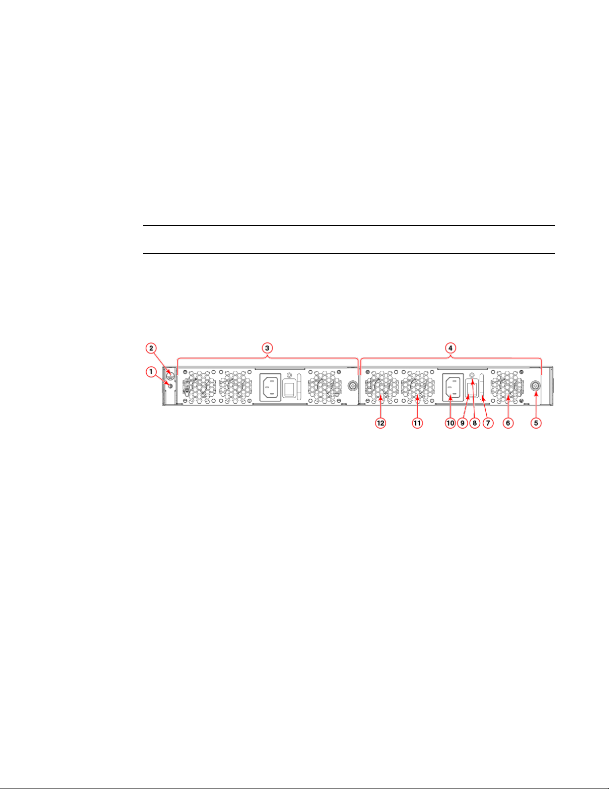
Nonport-side view
The following illustration shows the nonport-side view of the Brocade G620 FC switch.
1 Ground sticker
2 Ground cable connector
3 Power supply and fan assembly 2
4 Power supply and fan assembly 1
5 Captive screw
6 Fan 1
7 Handle
8 Power supply and fan assembly status
LED
9 Power-on switch
10 Power supply receptacle
11 Fan 2
12 Fan 3
FIGURE 2 Nonport-side view with AC power supply and fan assembly units
Device management options
You can use the management functions built into the device to monitor the fabric topology, port status,
physical status, and other information to help you analyze switch performance and to accelerate system
debugging. The device automatically performs power-on self-test (POST) each time it is turned on. Any
errors are recorded in the RASlog messages.
You can manage the device using any of the management options listed in the following table.
Nonport-side view
Brocade G620 Hardware Installation Guide 15
53-1003990-01

Management options for the deviceTABLE 3
Management tool Out-of-band
support
In-band support Reference documents
Command line interface
(CLI)
Up to two admin sessions
and four user sessions
simultaneously.
Ethernet or serial
connection
IP over Fibre Channel Fabric OS Administrator's Guide
Fabric OS Command Reference
Brocade EZSwitchSetup
EZSwitchSetup helps to
complete the basic
configuration for single-
switch setup.
Ethernet or serial
connection
IP over Fibre Channel Brocade G620 EZSwitchSetup
QuickStart Guide
Brocade EZSwitchSetup
Administrator's Guide
Brocade Web Tools Ethernet or serial
connection
IP over Fibre Channel Web Tools Administrator's Guide
Standard SNMP
applications
Ethernet or serial
connection
IP over Fibre Channel Fabric OS MIB Reference
Management Server Ethernet or serial
connection
Native in-band interface
(over HBA only)
Fabric OS Administrator's Guide
Fabric OS Command Reference
Brocade Network Advisor
(BNA)
BNA must be purchased
separately.
Ethernet or serial
connection
IP over Fibre Channel Brocade Network Advisor
documentation set
Device Overview
16 Brocade G620 Hardware Installation Guide
53-1003990-01
Preparing for Installation
● Safety precautions.......................................................................................................... 17
● Facility requirements....................................................................................................... 20
● Quick installation checklist.............................................................................................. 21
● Shipping carton contents.................................................................................................23
Safety precautions
When using this product, observe all danger, caution, and attention notices in this manual. The safety
notices are accompanied by symbols that represent the severity of the safety condition
Refer to Cautions and Danger Notices at the end of this guide for translations of safety notices for this
product.
General precautions
DANGER
The procedures in this manual are for qualified service personnel.
DANGER
Before beginning the installation, see the precautions in “Power precautions.”
DANGER
Be careful not to accidently insert your fingers into the fan tray while removing it from the
chassis. The fan may still be spinning at a high speed.
CAUTION
Changes or modifications made to this device that are not expressly approved by the party
responsible for compliance could void the user's authority to operate the equipment.
CAUTION
Disassembling any part of the power supply and fan assembly voids the warranty and regulatory
certifications. There are no user-serviceable parts inside the power supply and fan assembly.
CAUTION
Make sure the airflow around the front, sides, and back of the device is not restricted.
CAUTION
Ensure that the airflow direction of the power supply unit matches that of the installed fan tray.
The power supplies and fan trays are clearly labeled with either a green arrow with an "E", or an
orange arrow with an "I."
Brocade G620 Hardware Installation Guide 17
53-1003990-01
CAUTION
Never leave tools inside the chassis.
CAUTION
To protect the serial port from damage, keep the cover on the port when not in use.
CAUTION
If you do not install a module or a power supply in a slot, you must keep the slot filler panel in
place. If you run the chassis with an uncovered slot, the system will overheat.
CAUTION
Do not install the device in an environment where the operating ambient temperature might
exceed 40°C (104°F).
ESD precautions
DANGER
For safety reasons, the ESD wrist strap should contain a series 1 megaohm resistor.
CAUTION
Before plugging a cable into any port, be sure to discharge the voltage stored on the cable by
touching the electrical contacts to ground surface.
CAUTION
Static electricity can damage the chassis and other electronic devices. To avoid damage, keep
static-sensitive devices in their static-protective packages until you are ready to install them.
NOTE
Wear a wrist grounding strap connected to the chassis ground (if the device is plugged in) or to a
bench ground.
Power precautions
DANGER
Make sure that the power source circuits are properly grounded, then use the power cord
supplied with the device to connect it to the power source.
DANGER
If the installation requires a different power cord than the one supplied with the device, make
sure you use a power cord displaying the mark of the safety agency that defines the
regulations for power cords in your country. The mark is your assurance that the power cord
can be used safely with the device.
ESD precautions
18 Brocade G620 Hardware Installation Guide
53-1003990-01
DANGER
This device might have more than one power cord. To reduce the risk of electric shock,
disconnect all power cords before servicing.
DANGER
Remove both power cords before servicing.
DANGER
Disconnect the power cord from all power sources to completely remove power from the device.
DANGER
To avoid high voltage shock, do not open the device while the power is on.
DANGER
Risk of explosion if battery is replaced by an incorrect type. Dispose of used batteries according
to the instructions.
CAUTION
Use a separate branch circuit for each power cord, which provides redundancy in case one of
the circuits fails.
CAUTION
Ensure that the device does not overload the power circuits, wiring, and over-current protection.
To determine the possibility of overloading the supply circuits, add the ampere (amp) ratings of
all devices installed on the same circuit as the device. Compare this total with the rating limit for
the circuit. The maximum ampere ratings are usually printed on the devices near the input
power connectors.
CAUTION
The power supply switch must be in the off position when you insert the power supply into the
chassis. Damage to the switch can result if a live power supply is installed.
CAUTION
Carefully follow the mechanical guides on each side of the power supply slot and make sure the
power supply is properly inserted in the guides. Never insert the power supply upside down.
Lifting and weight-related precautions
DANGER
Use safe lifting practices when moving the product.
DANGER
Mount the devices you install in a rack as low as possible. Place the heaviest device at the
bottom and progressively place lighter devices above.
Lifting and weight-related precautions
Brocade G620 Hardware Installation Guide 19
53-1003990-01
DANGER
Make sure the rack housing the device is adequately secured to prevent it from becoming
unstable or falling over.
CAUTION
Do not use the port cover tabs to lift the module. They are not designed to support the weight
of the module, which can fall and be damaged.
CAUTION
To prevent damage to the chassis and components, never attempt to lift the chassis using the
fan or power supply handles. These handles were not designed to support the weight of the
chassis.
Laser precautions
DANGER
All fiber-optic interfaces use Class 1 lasers.
DANGER
Use only optical transceivers that are qualified by Brocade Communications Systems, Inc. and
comply with the FDA Class 1 radiation performance requirements defined in 21 CFR
Subchapter I, and with IEC 825 and EN60825. Optical products that do not comply with these
standards might emit light that is hazardous to the eyes.
Facility requirements
Before installing the device, be sure the following facilities requirements are met.
Facility requirements TABLE 4
Type Requirements
Electrical • Adequate supply circuit, line fusing, and wire size, as specified by the electrical
rating on the switch nameplate
• Circuit protected by a circuit breaker and grounded in accordance with local
electrical codes
Refer to the Technical Specifications at the end of this guide for complete power
supply specifications.
Laser precautions
20 Brocade G620 Hardware Installation Guide
53-1003990-01

Facility requirements (Continued)TABLE 4
Type Requirements
Thermal • A minimum airflow of 79.8 cubic meters/hour (47 cubic ft/min.) available in the
immediate vicinity of the switch
NOTE
Although this airflow may exceed the airflow maximum listed in the device
Technical Specifications, the additional airflow is recommended to pressurize the
inlet (cool isle) side of rack installations relative to the exhaust side to minimize
recirculation of hot air back to the inlet side.
• Ambient air temperature not exceeding 40°C (104°F) while the switch is operating
Rack (when rack-mounted) • One rack unit (1U) in a 48.3 cm (19-inch) rack
• All equipment in the rack grounded through a reliable branch circuit connection
• Additional weight of switch not to exceed the rack’s weight limits
• Rack secured to ensure stability in case of unexpected movement
Quick installation checklist
This checklist provides a high-level overview of the basic installation process from the planning stage to
the point where the device comes online and is ready to be deployed. Completing all the tasks in the
suggested order ensures successful installation. Brocade recommends that you print this checklist and
take it to the installation site.
Pre-installation tasks
Review all installation requirements ahead of time as part of your site preparation. Careful planning and
site preparation ensures seamless installation, especially when installing multiple devices.
Installation prerequisitesTABLE 5
Task Task details or additional information Completed
Unpack the device. Take an inventory of the hardware components included in your shipment. Refer to
Shipping carton contents on page 23.
Gather necessary components and
required tools.
Review the time and items required information at the beginning of each chapter to
ensure you have gathered all necessary components required for the following
installation tasks:
• Mounting the Device on page 25
• Power Supply and Fan Assembly on page 75
• Installing Transceivers and Cables on page 59
Review the safety precautions. Refer to Safety precautions on page 17. For translations, refer to Cautions and
Danger Notices on page 95 at the end of this guide.
Quick installation checklist
Brocade G620 Hardware Installation Guide 21
53-1003990-01

Installation prerequisites (Continued)TABLE 5
Task Task details or additional information Completed
Plan the installation. Decide whether you want to install the unit on a flat surface or in a rack. For rack
installation, obtain the appropriate rack mount kit. Refer to Mounting options on
page 25.
Review and verify installation
requirements.
Verify that the following requirements are met. Refer to Facility requirements on
page 20.
• Power requirements
• Environmental requirements
• Clearance for standalone or rack installation
Gather network configuration
parameters.
• IP address:
• Subnet mask:
• Default gateway:
• Domain ID:
• Time zone:
Installation and initial configuration
The initial setup includes mounting the device on a flat surface or in a rack and completing the
configuration tasks necessary to bring the device online and verify the operation.
Installation and basic system configuration TABLE 6
Task Task details or additional information Completed
Mount the device. Choose one of the following mounting options:
• Mount the device as a standalone unit. Refer to Standalone installation on page
26.
• Mount the device in a four-post rack. Refer to Installing the Universal Four-Post
Rack Kit (XBR-R000296) on page 26.
• Mount the device in a two-post rack. Refer to Installing the Universal Two-Post
Rack kit (XBR-R000294) on page 40.
Check the airflow of the power supply
and fan assembly
The airflow direction of the power supply and fan should match. The power
supplies and fan trays are clearly labeled with either a green arrow with an "E", or
an orange arrow with an "I." For more details, refer to Identifying the airflow
direction on page 77.
Gather all components required for the
initial setup.
Refer to Items required on page 51.
Provide power to the device. Refer to Providing power to the device on page 51.
Attach a management station, establish
a serial connection, and change the
default passwords (optional).
Refer to Establishing a first-time serial connection on page 52. After completing
this task, log in to the serial port to configure the device.
Set the IP address, subnet mask, and
the default gateway IP address.
Use the ipaddrset command to configure a static device IP address, subnet mask,
and gateway IP address, or you can use a DHCP server to obtain the information
dynamically. Refer to Configuring the IP address on page 53.
Preparing for Installation
22 Brocade G620 Hardware Installation Guide
53-1003990-01

Installation and basic system configuration (Continued)TABLE 6
Task Task details or additional information Completed
Set the date and time.
• Use the date command to display and set the date and time.
• Use the tstimezone command to display and set the time zone.
• Use the tsclockserver command to synchronize the time with an external NTP
server.
Refer to Setting the date and time on page 53 for more information.
Customize the switch name and chassis
name.
• Use the swicthname command to change the default switch name.
• Use the chassisname command to change the default chassis name.
Refer to Customizing the chassis name and switch name on page 55 for more
information.
Establish an Ethernet connection. By establishing an Ethernet connection, you can complete the device configuration
using a serial session, Telnet, or management application, such as Brocade
Network Advisor. Refer to Establishing an Ethernet connection on page 56.
Optional: Configure the DNS service. Use the dnsconfig command to create DNS server entries. Refer to the Fabric OS
Administrator's Guide.
Optional: Customize the domain ID. Use the configure command to change the domain ID (default ID is 1). Refer to
Setting the domain ID on page 56 for more information.
Verify that the device operates correctly.
• Check the LEDs to verify operation of functional parts. Refer to Interpreting
port-side LEDs on page 67 and Interpreting nonport-side LEDs on page 70.
• The following commands can be useful to establish an operational baseline for
the device. Refer to the Fabric OS Command Reference for more information
on these commands.
‐ psshow
‐ fanshow
‐ tempshow
‐ historyshow
‐ errdump
Back up the configuration. Use the interactive configupload command to back up the configuration. Refer to
Verifying correct operation on page 56 for more information.
Optional: Power off the devices. Enter the shutdown command and wait for the device to power down, and then
unplug the power cords. Refer to Powering down the device on page 58 for more
information.
Shipping carton contents
When unpacking the device, verify that the contents of the shipping carton is complete. Save the
shipping carton and packaging in the event you need to return the shipment.
• The Brocade G620 device
• An accessory kit containing the following items:
‐ A serial cable
‐ Two 6-ft. power cords
Shipping carton contents
Brocade G620 Hardware Installation Guide 23
53-1003990-01

‐ Power cord retainer clips
‐ Rubber feet.
‐ China-RoHS Hazardous/Toxic Substance statement
‐ Network Advisor web pointer card.
‐ EZSwitch web pointer card
‐ Brocade documentation web pointer card
• Inner foam
Preparing for Installation
24 Brocade G620 Hardware Installation Guide
53-1003990-01
Mounting the Device
● Mounting options.............................................................................................................25
● Precautions specific to mounting.................................................................................... 25
● Standalone installation ................................................................................................... 26
● Installing the Universal Four-Post Rack Kit (XBR-R000296).......................................... 26
● Installing the Universal Two-Post Rack kit (XBR-R000294)........................................... 40
Mounting options
You can install the device in several ways:
• As a standalone unit on a flat surface, for example, a table top. Use the rubber feet included with the
shipment to secure the device on the surface. No other equipment is required for desktop installation.
• In a four-post EIA rack: You will need a Universal Four-Post Rack Kit (XBR-R000296) to install
devices in EIA racks that are between L-13.7 to 81.28 cm deep (L-5.0 to 32.0 in.), where L is the
chassis depth.
• In a two-post Telco rack: You will need a Universal Two-Post Rack Kit (XBR-R000294) to install 1U
and 2U devices in a two-post telecommunications (Telco) rack.
NOTE
Review the Safety Precautions before mounting the device.
Precautions specific to mounting
The following precautions specifically apply to mounting the device.
DANGER
Use safe lifting practices when moving the product.
DANGER
Mount the devices you install in a rack as low as possible. Place the heaviest device at the
bottom and progressively place lighter devices above.
CAUTION
Make sure the airflow around the front, sides, and back of the device is not restricted.
CAUTION
Never leave tools inside the chassis.
Brocade G620 Hardware Installation Guide 25
53-1003990-01

CAUTION
Do not use the port cover tabs to lift the module. They are not designed to support the weight
of the module, which can fall and be damaged.
CAUTION
To prevent damage to the chassis and components, never attempt to lift the chassis using the
fan or power supply handles. These handles were not designed to support the weight of the
chassis.
Standalone installation
Complete the following steps to install the device as a standalone unit on a table.
1. Unpack the device and verify the items listed under Shipping carton contents on page 23 are
present and undamaged.
2. Apply the adhesive rubber feet to the underside of the device. The rubber feet help prevent the
device from sliding off the supporting surface.
a) Clean the indentations at each corner of the bottom of the device to ensure that they are free of
dust or other debris that might lessen the adhesion of the feet.
b) With the adhesive side against the chassis, place one rubber foot in each indentation and press
into place.
3. Place the device on a sturdy flat surface.
4. Provide power to the device as described in Providing power to the device on page 51.
NOTE
Do not connect the device to the network until the IP address is set correctly. For instructions on
how to set the IP address, refer to Configuring the IP address on page 53.
Installing the Universal Four-Post Rack Kit (XBR-R000296)
Use the following instructions to install a device in EIA racks that are between L-12.7 to 81.28 cm deep
(L-5.0 to 32.0 in.), where L is the chassis depth, using the Universal Four-Post Rack Kit (XBR-
R000296).
There are two ways you can mount the device in a four-post rack:
• With the port side flush with the front posts
• With the nonport side flush with the rear posts in a recessed position
A recessed position allows a more gradual bend in the fiber-optic cables connected to the switch and
less interference in the aisle at the front of the rack.
NOTE
Although this document describes how to install both single height (1U) and double height (2U)
switches, the illustrations show a 1U switch as a typical installation.
Standalone installation
26 Brocade G620 Hardware Installation Guide
53-1003990-01

NOTE
Hardware devices illustrated in these procedures are only for reference and may not depict the device
you are installing into the rack.
Installation requirements
Provide space in an EIA rack with the following minimum and maximum distances between the front
and back posts.
NOTE
For 1U and 2U devices, two people are required to install the device in a rack. One person holds the
device, while the other screws in the front and rear "L" brackets.
Space requirementsTABLE 7
Chassis with
port-side side
vents
Notes Chassis depth Minimum rack
depth
Maximum rack
depth
No Applicable to port-side and nonport-
side flush mounts.
L L-12.7 cm (L-5
in.)
81.28 cm (32 in.)
Yes Applicable to port-side flush mounts. L L-12.7 cm (L-5
in.)
81.28 cm (32 in.)
Yes Applicable to nonport-side flush
mounts.
L L 81.28 cm (32 in.)
Note that if chassis depth (L) is less than 40.64 cm (16 in.), the chassis will not fit into a rack with a
maximum depth of 81.28 cm (32 in.) using the universal four-post rack kit. The maximum rack depth for
a chassis less than 40.64 cm (16 in.) is 81.28 cm (32 in.) minus the difference between the chassis
depth and 40.64 cm (16 in.). For example, a chassis with a depth (L) of 35.56 cm (14 in.) is 5.08 cm (2
in.) smaller than 40.64 cm (16 in.), so it will install into a rack with a maximum depth of 81.28 cm (32 in.)
- 5.08 cm (2 in.) = 76.2 cm (30 in.).
• Verify that the additional weight of the device does not exceed the rack weight limits.
• Ensure that an electrical branch circuit with the following characteristics is available:
‐ Required voltage and frequency as indicated in the Technical Specifications (200-240 VAC is
always preferred).
‐ Protection by a circuit breaker in accordance with local electrical codes.
‐ Supply circuit, line fusing, and wire size that conform to the electrical rating on the device
nameplate.
‐ Grounded outlet compatible with the power cord and installed by a licensed electrician.
• Ensure that all equipment installed in the rack is grounded through a reliable branch circuit
connection. Do not rely on a secondary connection to a branch circuit, such as a power strip.
• Ensure that the rack is mechanically secured to ensure stability.
• Ensure that the air temperature at the fan inlet is less than 40
o
C (104
o
F) during device operation.
• Ensure that the airflow available at the air vents meets the minimum requirements for the device.
Installation requirements
Brocade G620 Hardware Installation Guide 27
53-1003990-01

NOTE
Install the device with the airflow aligned with any other devices in the rack. Some devices have airflow
running from port side to fan side and others have the opposite arrangement. Make sure that the
airflow for all devices moves in the same direction to maximize cooling.
Time and items required
Allow 15 to 30 minutes to complete the installation.
The following items are required to install the device using the Universal Four-Post Rack Kit:
• #2 Phillips torque screwdriver
• 1/4-inch slotted-blade torque screwdriver
Time and items required
28 Brocade G620 Hardware Installation Guide
53-1003990-01
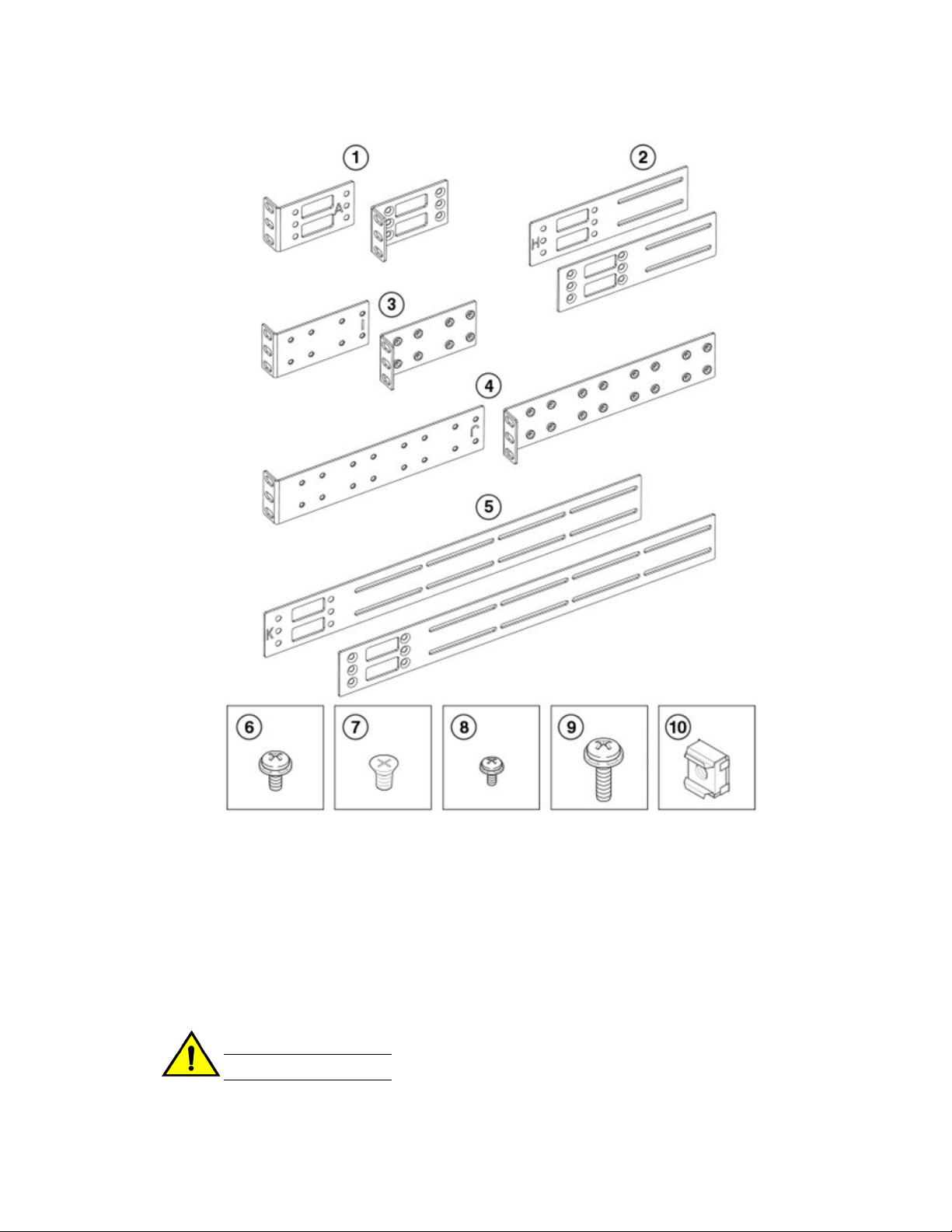
1 Front brackets (2)
2 Extension brackets, medium (2)
3 Rear brackets, short (2)
4 Rear brackets, long (2)
5 Extension brackets, long (2)
6 Screw, 8-32 x 5/16-in., panhead Phillips
(8)
7 Screw, 8-32 x 5/16-in., flathead Phillips
(16)
8 Screw, 6-32 x 1/4-in., panhead Phillips
(8)
9 Screw, 10-32 x 5/8-in., panhead Phillips
(8)
10 Retainer nut, 10-32 (8)
FIGURE 3 Items in the Universal Four-Post Rack Kit
Ensure that the items listed and illustrated in Figure 3 are included in the kit. Note that not all parts may
be used with certain installations depending on the device type.
CAUTION
Use the screws specified in the procedure. Using longer screws can damage the device.
Mounting the Device
Brocade G620 Hardware Installation Guide 29
53-1003990-01

Flush-front mounting
CAUTION
The device must be turned off and disconnected from the fabric during this procedure.
NOTE
The illustrations in the rack installation procedures show a 1U device, but the instructions are the
same for a 2U device. The illustrations in the rack installation procedures are for reference only and
may not show the actual device.
Complete the following tasks to install the device in a four-post rack:
1. Attaching the front brackets on page 30
2. Attaching the extension brackets to the device on page 31
3. Installing the device in the rack on page 32
4. Attaching the rear brackets to the extensions on page 33
5. Attaching the rear brackets to the rack posts on page 34
Attaching the front brackets
Complete the following steps to attach the front brackets to the device.
1. Position the right front bracket with the flat side against the right side of the device at the front of the
device, as shown in Figure 4 .
2. Insert four 8-32 x 5/16-in. flathead screws through the vertically aligned holes in the bracket and
then into the holes on the side of the device. Use the upper and lower screw holes, leaving the
center holes empty.
3. Repeat step 1 and step 2 to attach the left front bracket to the left side of the device.
4. Tighten all the 8-32 x 5/16-in. screws to a torque of 15 in-lb (17 cm-kg).
Flush-front mounting
30 Brocade G620 Hardware Installation Guide
53-1003990-01
Loading...