


®
'HOO 'LPHQVLRQŠ ;36 '[[[ 6\VWHPV
5()(5(1&( $1'
7528%/(6+227,1*
*8,'(
ZZZ GHOO FRP
____________________
Information in this document is subject to change without notice. © 1998 Dell Computer Corporation. All rights reserved.
Reproduction in any manner whatsoever without the written permission of Dell Computer Corporation is strictly forbidden.
Trademarks used in this text: Dell, the DELL logo, and Dell Dimension are registered trademarks and DellWare is a registered service mark of Dell Computer Corporation; Intel and Pentium are registered trademarks and MMX is a trademark of Intel Corporation; MS-DOS, Microsoft, Windows, and Windows NT are registered trademarks of Microsoft Corporation; VESA is a registered trademark of Video Electronics Standards Association.
Other trademarks and trade names may be used in this document to refer to either the entities claiming the marks and names or their products. Dell Computer Corporation disclaims any proprietary interest in trademarks and trade names other than its own.
April 1998 P/N 0176C

6DIHW\ ,QVWUXFWLRQV
Use the following safety guidelines to help protect your computer system from potential damage and to ensure your own personal safety.
:KHQ 8VLQJ <RXU &RPSXWHU 6\VWHP
As you use your computer system, observe the following safety guidelines.
:$51,1* 'R QRW RSHUDWH \RXU FRPSXWHU V\VWHP ZLWK DQ\ FRYHU V LQFOXG LQJ FRPSXWHU FRYHUV EH]HOV ILOOHU EUDFNHWV IURQW SDQHO LQVHUWV DQG VR RQ UHPRYHG
‡To help avoid damaging your computer, be sure the voltage selection switch on the power supply is set to match the AC power available at your location:
—115 volts (V)/60 hertz (Hz) in most of North and South America and some Far Eastern countries such as Japan, South Korea, and Taiwan
—230 V/50 Hz in most of Europe, the Middle East, and the Far East
Also be sure your monitor and attached devices are electrically rated to operate with the AC power available in your location.
‡To help prevent electric shock, plug the computer and device power cables into properly grounded power sources. These cables are equipped with 3-prong plugs to help ensure proper grounding. Do not use adapter plugs or remove the grounding prong from a cable. If you must use an extension cable, use a 3-wire cable with properly grounded plugs.
‡To help avoid possible damage to the system board, wait 5 seconds after turning off the system before disconnecting a device from the computer.
‡To help protect your computer system from sudden, transient increases and decreases in electrical power, use a surge suppressor, line conditioner, or uninterruptible power supply (UPS).
‡Be sure nothing rests on your computer system’s cables and that the cables are not located where they can be stepped on or tripped over.
‡Do not spill food or liquids on your computer. If the computer gets wet, consult “If Your Computer Gets Wet” in Chapter 6.
v

‡Do not push any objects into the openings of your computer. Doing so can cause fire or electric shock by shorting out interior components.
‡Keep your computer away from radiators and heat sources. Also, do not block cooling vents. Avoid placing loose papers underneath your computer, and do not place your computer in a closed-in wall unit or on a bed, sofa, or rug.
(UJRQRPLF &RPSXWLQJ +DELWV
:$51,1* ,PSURSHU RU SURORQJHG NH\ERDUG XVH PD\ UHVXOW LQ LQMXU\
For comfort and efficiency, observe the following ergonomic guidelines when setting up and using your computer system:
‡Position your system so that the monitor and keyboard are directly in front of you as you work. Special shelves are available (from Dell and other sources) to help you correctly position your keyboard.
‡Set the monitor at a comfortable viewing distance (usually 510 to 610 millimeters [20 to 24 inches] from your eyes).
‡Make sure the monitor screen is at eye level or slightly lower when you are sitting in front of the monitor.
‡Adjust the tilt of the monitor, its contrast and brightness settings, and the lighting around you (such as overhead lights, desk lamps, and the curtains or blinds on nearby windows) to minimize reflections and glare on the monitor screen.
‡Use a chair that provides good lower back support.
‡Keep your forearms horizontal with your wrists in a neutral, comfortable position while using the keyboard or mouse.
‡Always leave space to rest your hands while using the keyboard or mouse.
‡Let your upper arms hang naturally at your sides.
‡Sit erect, with your feet resting on the floor and your thighs level.
‡When sitting, make sure the weight of your legs is on your feet and not on the front of your chair seat. Adjust your chair’s height or use a footrest, if necessary, to maintain proper posture.
‡Vary your work activities. Try to organize your work so that you do not have to type for extended periods of time. When you stop typing, try to do things that use both hands.
vi

monitor screen at or below eye level
monitor and keyboard positioned directly in front of user
wrists relaxed and flat
arms at desk level
feet flat on the floor
:KHQ :RUNLQJ ,QVLGH <RXU &RPSXWHU
Before you remove the computer cover, perform the following steps in the sequence indicated.
&$87,21 'R QRW DWWHPSW WR VHUYLFH WKH FRPSXWHU V\VWHP \RXUVHOI H[FHSW DV H[SODLQHG LQ WKLV JXLGH DQG HOVHZKHUH LQ 'HOO GRFXPHQWDWLRQ $OZD\V IROORZ LQVWDOODWLRQ DQG VHUYLFH LQVWUXFWLRQV FORVHO\
7XUQ RII \RXU FRPSXWHU DQG DQ\ GHYLFHV
'LVFRQQHFW \RXU FRPSXWHU DQG GHYLFHV IURP WKHLU SRZHU VRXUFHV $OVR GLVFRQQHFW DQ\ WHOHSKRQH RU WHOHFRPPXQLFDWLRQ OLQHV IURP WKH FRPSXWHU WR UHGXFH WKH SRWHQWLDO IRU SHUVRQDO LQMXU\ RU VKRFN
Certain system board components continue to receive power any time the computer is connected to AC power.
:HDU D ZULVW JURXQGLQJ VWUDS RU WRXFK DQ XQSDLQWHG PHWDO VXUIDFH RQ WKH FKDVVLV VXFK DV WKH SRZHU VXSSO\ EUDFNHW EHIRUH WRXFKLQJ DQ\ WKLQJ LQVLGH \RXU FRPSXWHU
While you work, periodically touch an unpainted metal surface on the computer chassis to dissipate any static electricity that might harm internal components.
vii

In addition, take note of these safety guidelines when appropriate:
‡When you disconnect a cable, pull on its connector or on its strain-relief loop, not on the cable itself. Some cables have a connector with locking tabs; to disconnect this type of cable, press in the locking tabs before disconnecting the cable. As you pull connectors apart, keep them evenly aligned to avoid bending any connector pins. Also, before you connect a cable, make sure both connectors are correctly oriented and aligned.
‡Handle components and cards with care. Don’t touch the components or contacts on a card. Hold a card by its edges or by its metal mounting bracket.
:$51,1*
7KHUH LV D GDQJHU RI D QHZ EDWWHU\ H[SORGLQJ LI LW LV LQFRUUHFWO\ LQVWDOOHG 5HSODFH WKH EDWWHU\ RQO\ ZLWK WKH VDPH RU HTXLYDOHQW W\SH UHFRPPHQGHG E\ WKH PDQXIDFWXUHU 'LVFDUG XVHG EDWWHULHV DFFRUGLQJ WR WKH PDQXIDF WXUHU·V LQVWUXFWLRQV
3URWHFWLQJ $JDLQVW (OHFWURVWDWLF 'LVFKDUJH
Static electricity can harm delicate components inside your computer. To prevent static damage, discharge static electricity from your body before you touch any of your computer’s electronic components, such as expansion cards. You can do so by touching an unpainted metal surface on the computer chassis.
As you continue to work inside the computer, periodically touch an unpainted metal surface to remove any static charge your body may have accumulated. Use of a wrist grounding strap is highly recommended.
You can also take the following steps to prevent damage from electrostatic discharge (ESD):
‡Keep a static-sensitive component in its antistatic packing material until you are ready to install the component in your computer. Just before unwrapping the antistatic packaging, discharge static electricity from your body.
‡Transport sensitive components in antistatic containers or packaging.
‡Handle all sensitive components in a static-safe area. If possible, use antistatic floor pads and workbench pads.
viii

3UHIDFH
$ERXW 7KLV *XLGH
This guide is intended for anyone who uses a Dell Dimension XPS Dxxx computer system. It can be used by both first-time and experienced computer users who want to maintain, upgrade, or troubleshoot their computers. The chapters and appendixes are summarized as follows:
‡Everyone should read Chapter 1, “Introduction,” for an overview of the system features and information on preventative maintenance to protect the computer.
‡Chapter 2, “Installing Upgrades on the System Board,” provides information on performing various upgrades, such as installing additional memory or drives. The chapter includes a basic orientation to internal features of the computer.
‡Users who add or remove drives should consult Chapter 3, “Installing Drives.”
‡Chapter 4, “Basic Troubleshooting,” contains checklists to use before calling Dell for technical assistance.
‡Chapter 5, “Software Solutions,” has information on reinstalling drivers and the operating system.
‡Chapter 6, “Checking Inside Your Computer,” presents troubleshooting procedures for system components such as expansion cards, memory, and drives.
‡Chapter 7, “Running the Dell Diagnostics,” describes the Dell Diagnostics program used to test your computer system.
‡Users who have been unable to resolve problems using the troubleshooting information provided in this guide can refer to Chapter 8, “Getting Help,” for information on obtaining technical assistance.
‡Appendix A, “System Specifications,” is supplemental reference material.
‡Appendix B, “System Setup Program,” describes the system setup program used for checking and changing system configuration data.
‡Appendix C, “Beep Codes and System Messages,” documents status and error messages generated during system start-up. Included are possible causes and corrective actions.
‡Appendix D, “Regulatory Notices,” provides regulatory information on the system.
ix

‡Appendix E, “Warranties and Return Policy,” describes the warranty for your Dell system and the “Total Satisfaction” Return Policy.
:DUUDQW\ DQG 5HWXUQ 3ROLF\ ,QIRUPDWLRQ
Dell Computer Corporation (“Dell”) manufactures its hardware products from parts and components that are new or equivalent to new in accordance with industrystandard practices. For information about the Dell warranty for your system, see Appendix E, “Warranties and Return Policy.”
2WKHU 'RFXPHQWV <RX 0D\ 1HHG
Besides this Reference and Troubleshooting Guide, the following documentation is included with your system:
‡The Getting Started sheet provides step-by-step instructions for setting up your computer system.
‡The Dell Dimension XPS Dxxx Systems Setup Guide contains information necessary to properly configure your system for operation, access the Internet, and use software and hardware. The guide also provides answers to questions that are often asked by Dell computer users.
‡The Windows-based Online Guide presents in an online format information from the Setup Guide and from this guide. This document is located in the Dell Accessories folder.
You may also have one or more of the following documents.
NOTE: Documentation updates are sometimes included with your system to describe changes to your system or software. Always read these updates before consulting any other documentation because the updates often contain the latest information.
‡Operating system documentation is included if you ordered your operating system software from Dell.
‡Video card documentation from the card manufacturer describes the video drivers included with the system. Only users who want to change the default video driver or reinstall the video driver need to read this documentation.
‡Documentation is included with any options you purchase separately from your system. The documentation contains configuration information and supplements the installation instructions provided in this guide.
‡The Dell Service and Support Plans is an online reference to Dell’s service and support plans, guarantees, and warranties. It applies to the United States only. This document is located in the Dell Accessories folder.
‡Technical information files—sometimes called “readme” files—may be installed on your hard-disk drive to provide last-minute updates about technical changes to your system or reference material intended for experienced users.
x

1RWDWLRQDO &RQYHQWLRQV
The following subsections describe notational conventions used in this document.
:DUQLQJV &DXWLRQV DQG 1RWHV
Throughout this guide, there may be blocks of text indicated by symbols in the page margin and printed in bold type or in italic type. These blocks are warnings, cautions, and notes, and they are used as follows:
:$51,1* $ :$51,1* LQGLFDWHV WKH SRWHQWLDO IRU ERGLO\ KDUP DQG WHOOV \RX KRZ WR DYRLG WKH SUREOHP
&$87,21 $ &$87,21 LQGLFDWHV HLWKHU SRWHQWLDO GDPDJH WR KDUGZDUH RU ORVV RI GDWD DQG WHOOV \RX KRZ WR DYRLG WKH SUREOHP
NOTE: A NOTE indicates important information that helps you make better use of your computer system.
7\SRJUDSKLFDO &RQYHQWLRQV
The following list defines (where appropriate) and illustrates typographical conventions used as visual cues for specific elements of text throughout this document:
‡Keycaps, the labeling that appears on the keys on a keyboard, are enclosed in angle brackets.
Example: <Enter>
‡Key combinations are series of keys to be pressed simultaneously (unless otherwise indicated) to perform a single function.
Example: <Ctrl><Alt><Enter>
‡Commands presented in lowercase bold are for reference purposes only and are not intended to be typed when referenced.
Example: “Use the format command to . . . .”
In contrast, commands presented in the Courier New font are part of an instruction and intended to be typed.
Example: “Type format a: to format the diskette in drive A.”
‡Filenames and directory names are presented in lowercase bold. Examples: autoexec.bat and c:\ windows
‡Syntax lines consist of a command and all its possible parameters. Commands are displayed in lowercase bold; variable parameters (those for which you substitute a value) are displayed in lowercase italics; constant parameters are displayed in lowercase bold. The brackets indicate items that are optional.
Example: del [drive:] [path] filename [/p]
xi
‡Screen text is text that appears on the monitor screen. It can be a message, or it can be text that you are instructed to type as part of a command (referred to as a command line). Screen text is presented in the Courier New font.
Example: The following message appears on your screen:
No boot device available
Example: “Type md c:\programs and press <Enter>.”
‡Variables are placeholders for which you substitute a value. They are presented in italics.
Example: DIMMx (where x represents the DIMM socket designation).
xii
&RQWHQWV
&KDSWHU |
,QWURGXFWLRQ |
|
|
Hardware Features . . . . . . . . . . . . . . . . . . . . . . . . . . . . . . . . . . . . . . . . . . . . . . . . . |
1-1 |
|
Software Features . . . . . . . . . . . . . . . . . . . . . . . . . . . . . . . . . . . . . . . . . . . . . . . . . . |
1-3 |
|
Available Upgrades . . . . . . . . . . . . . . . . . . . . . . . . . . . . . . . . . . . . . . . . . . . . . . . . . |
1-3 |
|
Preventative Maintenance. . . . . . . . . . . . . . . . . . . . . . . . . . . . . . . . . . . . . . . . . . . . |
1-4 |
|
Preserving Data . . . . . . . . . . . . . . . . . . . . . . . . . . . . . . . . . . . . . . . . . . . . . . . . |
1-4 |
|
Scheduling Backups . . . . . . . . . . . . . . . . . . . . . . . . . . . . . . . . . . . . . . . . . |
1-5 |
|
Backup Devices. . . . . . . . . . . . . . . . . . . . . . . . . . . . . . . . . . . . . . . . . . . . . |
1-5 |
|
Virus-Scanning Software and Data Transfers . . . . . . . . . . . . . . . . . . . . . . . . . . |
1-5 |
|
Cleaning System Components. . . . . . . . . . . . . . . . . . . . . . . . . . . . . . . . . . . . . |
1-5 |
|
Recommended Tools and Accessories. . . . . . . . . . . . . . . . . . . . . . . . . . . |
1-5 |
|
Cleaning the Computer, Monitor, and Keyboard Exteriors . . . . . . . . . . . . |
1-6 |
|
Cleaning the Mouse . . . . . . . . . . . . . . . . . . . . . . . . . . . . . . . . . . . . . . . . . |
1-6 |
|
Cleaning Drives . . . . . . . . . . . . . . . . . . . . . . . . . . . . . . . . . . . . . . . . . . . . . |
1-7 |
|
Power Protection Devices . . . . . . . . . . . . . . . . . . . . . . . . . . . . . . . . . . . . . . . . |
1-7 |
|
Surge Protectors . . . . . . . . . . . . . . . . . . . . . . . . . . . . . . . . . . . . . . . . . . . . |
1-7 |
|
Line Conditioners . . . . . . . . . . . . . . . . . . . . . . . . . . . . . . . . . . . . . . . . . . . |
1-7 |
|
Uninterruptible Power Supply . . . . . . . . . . . . . . . . . . . . . . . . . . . . . . . . . . |
1-7 |
&KDSWHU |
,QVWDOOLQJ 8SJUDGHV RQ WKH 6\VWHP %RDUG |
|
|
Safety First—For You and Your Computer . . . . . . . . . . . . . . . . . . . . . . . . . . . . . . |
. 2-1 |
|
Installation Guidelines . . . . . . . . . . . . . . . . . . . . . . . . . . . . . . . . . . . . . . . . . . . . . . . |
2-2 |
|
Removing and Replacing the Computer Cover . . . . . . . . . . . . . . . . . . . . . . . . . . . . |
2-2 |
|
Inside Your Computer . . . . . . . . . . . . . . . . . . . . . . . . . . . . . . . . . . . . . . . . . . . . . . . |
2-3 |
|
System Board . . . . . . . . . . . . . . . . . . . . . . . . . . . . . . . . . . . . . . . . . . . . . . . . . . . . . |
2-6 |
|
Jumpers . . . . . . . . . . . . . . . . . . . . . . . . . . . . . . . . . . . . . . . . . . . . . . . . . . . . . . |
2-8 |
|
Expansion Card Upgrades . . . . . . . . . . . . . . . . . . . . . . . . . . . . . . . . . . . . . . . . . . |
2-10 |
|
Installing Expansion Cards . . . . . . . . . . . . . . . . . . . . . . . . . . . . . . . . . . . . . . . |
2-11 |
|
Removing Expansion Cards . . . . . . . . . . . . . . . . . . . . . . . . . . . . . . . . . . . . . . |
2-13 |
xiii
|
Adding Memory . . . . . . . . . . . . . . . . . . . . . . . . . . . . . . . . . . . . . . . . . . . . . . . . . . |
2-14 |
|
Memory Upgrade Kits . . . . . . . . . . . . . . . . . . . . . . . . . . . . . . . . . . . . . . . . . . |
2-14 |
|
Installing a DIMM . . . . . . . . . . . . . . . . . . . . . . . . . . . . . . . . . . . . . . . . . . . . . |
2-15 |
|
Removing a DIMM. . . . . . . . . . . . . . . . . . . . . . . . . . . . . . . . . . . . . . . . . . . . . |
2-16 |
|
Replacing the System Battery. . . . . . . . . . . . . . . . . . . . . . . . . . . . . . . . . . . . . . . . |
2-17 |
&KDSWHU |
,QVWDOOLQJ 'ULYHV |
|
|
Removing and Replacing the Bezel. . . . . . . . . . . . . . . . . . . . . . . . . . . . . . . . . . . . |
. 3-1 |
|
Removing and Replacing the Drive Cage . . . . . . . . . . . . . . . . . . . . . . . . . . . . . . . . |
3-2 |
|
Removing the Drive Cage . . . . . . . . . . . . . . . . . . . . . . . . . . . . . . . . . . . . . . . . |
3-2 |
|
Replacing the Drive Cage. . . . . . . . . . . . . . . . . . . . . . . . . . . . . . . . . . . . . . . . . |
3-3 |
|
Removing and Replacing a Front-Panel Insert . . . . . . . . . . . . . . . . . . . . . . . . . . . . |
3-4 |
|
Configuring Drives. . . . . . . . . . . . . . . . . . . . . . . . . . . . . . . . . . . . . . . . . . . . . . . . . . |
3-4 |
|
Connecting Drives. . . . . . . . . . . . . . . . . . . . . . . . . . . . . . . . . . . . . . . . . . . . . . . . . . |
3-5 |
|
Installing Externally Accessible Drives . . . . . . . . . . . . . . . . . . . . . . . . . . . . . . . . . . |
3-6 |
|
5.25-Inch Drives . . . . . . . . . . . . . . . . . . . . . . . . . . . . . . . . . . . . . . . . . . . . . . . . |
3-6 |
|
3.5-Inch Drives . . . . . . . . . . . . . . . . . . . . . . . . . . . . . . . . . . . . . . . . . . . . . . . . . |
3-8 |
|
Upper 3.5-Inch Bay . . . . . . . . . . . . . . . . . . . . . . . . . . . . . . . . . . . . . . . . . . |
3-8 |
|
Lower 3.5-Inch Bay (Mini Tower Chassis Only) . . . . . . . . . . . . . . . . . . . |
3-11 |
|
Installing EIDE Hard-Disk Drives . . . . . . . . . . . . . . . . . . . . . . . . . . . . . . . . . . . . . . |
3-13 |
|
Primary Hard-Disk Drive Bay . . . . . . . . . . . . . . . . . . . . . . . . . . . . . . . . . . . . . |
3-13 |
|
Secondary Hard-Disk Drive Bay . . . . . . . . . . . . . . . . . . . . . . . . . . . . . . . . . . . |
3-14 |
|
Partitioning and Logically Formatting an EIDE Hard-Disk Drive . . . . . . . . . |
3-17 |
|
Installing SCSI Devices . . . . . . . . . . . . . . . . . . . . . . . . . . . . . . . . . . . . . . . . . . . . |
3-17 |
|
SCSI Configuration Guidelines . . . . . . . . . . . . . . . . . . . . . . . . . . . . . . . . . . . |
3-17 |
|
SCSI ID Numbers . . . . . . . . . . . . . . . . . . . . . . . . . . . . . . . . . . . . . . . . . . |
3-18 |
|
SCSI Cables and SCSI Termination. . . . . . . . . . . . . . . . . . . . . . . . . . . . . |
3-18 |
|
General Procedure for Installing SCSI Devices . . . . . . . . . . . . . . . . . . . . . . . |
3-19 |
|
Partitioning and Formatting SCSI Hard-Disk Drives . . . . . . . . . . . . . . . . . |
3-21 |
&KDSWHU |
%DVLF 7URXEOHVKRRWLQJ |
|
|
Backing Up Data Files . . . . . . . . . . . . . . . . . . . . . . . . . . . . . . . . . . . . . . . . . . . . . . . |
4-1 |
|
Checking the Basics . . . . . . . . . . . . . . . . . . . . . . . . . . . . . . . . . . . . . . . . . . . . . . . . |
4-1 |
|
Connections . . . . . . . . . . . . . . . . . . . . . . . . . . . . . . . . . . . . . . . . . . . . . . . . . . . |
4-2 |
|
Environmental Factors . . . . . . . . . . . . . . . . . . . . . . . . . . . . . . . . . . . . . . . . . . . |
4-3 |
|
Power. . . . . . . . . . . . . . . . . . . . . . . . . . . . . . . . . . . . . . . . . . . . . . . . . . . . . . . . |
4-4 |
|
Boot Routine . . . . . . . . . . . . . . . . . . . . . . . . . . . . . . . . . . . . . . . . . . . . . . . . . . |
4-4 |
|
Monitor . . . . . . . . . . . . . . . . . . . . . . . . . . . . . . . . . . . . . . . . . . . . . . . . . . . . . . |
4-5 |
|
Speakers . . . . . . . . . . . . . . . . . . . . . . . . . . . . . . . . . . . . . . . . . . . . . . . . . . . . . |
4-6 |
|
Modem . . . . . . . . . . . . . . . . . . . . . . . . . . . . . . . . . . . . . . . . . . . . . . . . . . . . . . |
4-7 |
|
Drives. . . . . . . . . . . . . . . . . . . . . . . . . . . . . . . . . . . . . . . . . . . . . . . . . . . . . . . . |
4-7 |
xiv
&KDSWHU |
6RIWZDUH 6ROXWLRQV |
|
|
Using Audio Utilities . . . . . . . . . . . . . . . . . . . . . . . . . . . . . . . . . . . . . . . . . . . . . . . |
. 5-1 |
|
Enabling Enhanced 3D Audio . . . . . . . . . . . . . . . . . . . . . . . . . . . . . . . . . . . . . . |
5-1 |
|
Adjusting Enhanced 3D Audio . . . . . . . . . . . . . . . . . . . . . . . . . . . . . . . . . . . . . |
5-2 |
|
Yamaha S-YXG50 Wave-Table Software (Windows 95 Only) . . . . . . . . . . . . . |
5-3 |
|
Reinstalling Drivers . . . . . . . . . . . . . . . . . . . . . . . . . . . . . . . . . . . . . . . . . . . . . . . . . |
5-3 |
|
Video Drivers . . . . . . . . . . . . . . . . . . . . . . . . . . . . . . . . . . . . . . . . . . . . . . . . . . |
5-3 |
|
Audio Drivers . . . . . . . . . . . . . . . . . . . . . . . . . . . . . . . . . . . . . . . . . . . . . . . . . . |
5-4 |
|
Audio Drivers for Windows 95 . . . . . . . . . . . . . . . . . . . . . . . . . . . . . . . . . |
5-4 |
|
Audio Drivers for Windows NT 4.0 . . . . . . . . . . . . . . . . . . . . . . . . . . . . . . |
5-5 |
|
Bus-Mastering EIDE Drivers . . . . . . . . . . . . . . . . . . . . . . . . . . . . . . . . . . . . . . |
5-6 |
|
Bus-Mastering EIDE Driver for Windows 95. . . . . . . . . . . . . . . . . . . . . . . |
5-6 |
|
Bus-Mastering EIDE Driver for Windows NT 4.0 . . . . . . . . . . . . . . . . . . . |
5-6 |
|
Removing the Windows NT 4.0 Bus-Mastering EIDE Driver . . . . . . . . . . |
5-8 |
|
PIIX4 Drivers. . . . . . . . . . . . . . . . . . . . . . . . . . . . . . . . . . . . . . . . . . . . . . . . . . . |
5-8 |
|
Resolving Software and Hardware Incompatibilities . . . . . . . . . . . . . . . . . . . . . . . . |
5-9 |
|
Reinstalling Windows . . . . . . . . . . . . . . . . . . . . . . . . . . . . . . . . . . . . . . . . . . . . . . . |
5-9 |
|
Installing the Intel PIIX4 INF Update for Windows 95 . . . . . . . . . . . . . . . . . . |
5-10 |
|
Installing the USB Supplement . . . . . . . . . . . . . . . . . . . . . . . . . . . . . . . . . . . |
5-11 |
|
Reinstalling Internet Explorer 4.x . . . . . . . . . . . . . . . . . . . . . . . . . . . . . . . . . . |
5-12 |
&KDSWHU |
&KHFNLQJ ,QVLGH <RXU &RPSXWHU |
|
|
Expansion Cards . . . . . . . . . . . . . . . . . . . . . . . . . . . . . . . . . . . . . . . . . . . . . . . . . . |
. 6-1 |
|
Modem. . . . . . . . . . . . . . . . . . . . . . . . . . . . . . . . . . . . . . . . . . . . . . . . . . . . . . |
. 6-3 |
|
Sound Cards . . . . . . . . . . . . . . . . . . . . . . . . . . . . . . . . . . . . . . . . . . . . . . . . . . . |
6-4 |
|
Video Cards . . . . . . . . . . . . . . . . . . . . . . . . . . . . . . . . . . . . . . . . . . . . . . . . . . . |
6-4 |
|
Network Cards . . . . . . . . . . . . . . . . . . . . . . . . . . . . . . . . . . . . . . . . . . . . . . . . . |
6-4 |
|
System Memory . . . . . . . . . . . . . . . . . . . . . . . . . . . . . . . . . . . . . . . . . . . . . . . . . . . |
6-5 |
|
Reseating DIMMs . . . . . . . . . . . . . . . . . . . . . . . . . . . . . . . . . . . . . . . . . . . . . . |
6-6 |
|
Drives . . . . . . . . . . . . . . . . . . . . . . . . . . . . . . . . . . . . . . . . . . . . . . . . . . . . . . . . . . . |
6-6 |
|
Diskette Drive. . . . . . . . . . . . . . . . . . . . . . . . . . . . . . . . . . . . . . . . . . . . . . . . . . |
6-7 |
|
CD-ROM and DVD-ROM Drives. . . . . . . . . . . . . . . . . . . . . . . . . . . . . . . . . . . . |
6-7 |
|
Hard-Disk Drive . . . . . . . . . . . . . . . . . . . . . . . . . . . . . . . . . . . . . . . . . . . . . . . . |
6-7 |
|
System Board . . . . . . . . . . . . . . . . . . . . . . . . . . . . . . . . . . . . . . . . . . . . . . . . . . . . . |
6-8 |
|
Reseating the Microprocessor . . . . . . . . . . . . . . . . . . . . . . . . . . . . . . . . . . . . . . . . |
6-9 |
|
If Your Computer Gets Wet. . . . . . . . . . . . . . . . . . . . . . . . . . . . . . . . . . . . . . . . . . |
6-11 |
|
If Your Computer Is Damaged. . . . . . . . . . . . . . . . . . . . . . . . . . . . . . . . . . . . . . . . |
6-12 |
xv
&KDSWHU |
5XQQLQJ WKH 'HOO 'LDJQRVWLFV |
When to Use the Dell Diagnostics . . . . . . . . . . . . . . . . . . . . . . . . . . . . . . . . . . . . . 7-1 Before You Start Testing. . . . . . . . . . . . . . . . . . . . . . . . . . . . . . . . . . . . . . . . . . . . . 7-2 Starting the Dell Diagnostics. . . . . . . . . . . . . . . . . . . . . . . . . . . . . . . . . . . . . . . . . . 7-2 Running the Diagnostics Once . . . . . . . . . . . . . . . . . . . . . . . . . . . . . . . . . . . . 7-2 Cycling the Tests to Catch Intermittent Failures . . . . . . . . . . . . . . . . . . . . . . . 7-3 Main Screen of the Dell Diagnostics. . . . . . . . . . . . . . . . . . . . . . . . . . . . . . . . . . . . 7-3 How to Use the Menus. . . . . . . . . . . . . . . . . . . . . . . . . . . . . . . . . . . . . . . . . . . . . . 7-4 Run. . . . . . . . . . . . . . . . . . . . . . . . . . . . . . . . . . . . . . . . . . . . . . . . . . . . . . . . . . 7-5 Select . . . . . . . . . . . . . . . . . . . . . . . . . . . . . . . . . . . . . . . . . . . . . . . . . . . . . . . . 7-5 Subtest. . . . . . . . . . . . . . . . . . . . . . . . . . . . . . . . . . . . . . . . . . . . . . . . . . . . . . . 7-5 Run Under Subtest . . . . . . . . . . . . . . . . . . . . . . . . . . . . . . . . . . . . . . . . . . 7-5 Select Under Subtest . . . . . . . . . . . . . . . . . . . . . . . . . . . . . . . . . . . . . . . . 7-5 Options Under Subtest . . . . . . . . . . . . . . . . . . . . . . . . . . . . . . . . . . . . . . . 7-6 Test Limits Under Subtest . . . . . . . . . . . . . . . . . . . . . . . . . . . . . . . . . . . . 7-6 About Under Subtest . . . . . . . . . . . . . . . . . . . . . . . . . . . . . . . . . . . . . . . . 7-6 Key-Help Under Subtest . . . . . . . . . . . . . . . . . . . . . . . . . . . . . . . . . . . . . . 7-6 Quit Menu Under Subtest . . . . . . . . . . . . . . . . . . . . . . . . . . . . . . . . . . . . 7-6 Options . . . . . . . . . . . . . . . . . . . . . . . . . . . . . . . . . . . . . . . . . . . . . . . . . . . . . . 7-6 Test Limits . . . . . . . . . . . . . . . . . . . . . . . . . . . . . . . . . . . . . . . . . . . . . . . . . . . . 7-7 About . . . . . . . . . . . . . . . . . . . . . . . . . . . . . . . . . . . . . . . . . . . . . . . . . . . . . . . . 7-8 Key-Help. . . . . . . . . . . . . . . . . . . . . . . . . . . . . . . . . . . . . . . . . . . . . . . . . . . . . . 7-8 Quit . . . . . . . . . . . . . . . . . . . . . . . . . . . . . . . . . . . . . . . . . . . . . . . . . . . . . . . . . 7-8
Diagnostics Tests . . . . . . . . . . . . . . . . . . . . . . . . . . . . . . . . . . . . . . . . . . . . . . . . . . 7-8 RAM Test Group . . . . . . . . . . . . . . . . . . . . . . . . . . . . . . . . . . . . . . . . . . . . . . . 7-9 System Set Test Group . . . . . . . . . . . . . . . . . . . . . . . . . . . . . . . . . . . . . . . . . . 7-9 Video Test Group . . . . . . . . . . . . . . . . . . . . . . . . . . . . . . . . . . . . . . . . . . . . . . 7-11 Keyboard Test Group . . . . . . . . . . . . . . . . . . . . . . . . . . . . . . . . . . . . . . . . . . . 7-12 Mouse Test . . . . . . . . . . . . . . . . . . . . . . . . . . . . . . . . . . . . . . . . . . . . . . . . . . 7-12 Diskette Drives Test Group . . . . . . . . . . . . . . . . . . . . . . . . . . . . . . . . . . . . . . 7-13 IDE (ATA/ATAPI) Devices Test Group . . . . . . . . . . . . . . . . . . . . . . . . . . . . . . 7-13 Serial/Infrared Ports Test Group. . . . . . . . . . . . . . . . . . . . . . . . . . . . . . . . . . . 7-15 Parallel Ports Test Group . . . . . . . . . . . . . . . . . . . . . . . . . . . . . . . . . . . . . . . . 7-16 SCSI Devices Test Group. . . . . . . . . . . . . . . . . . . . . . . . . . . . . . . . . . . . . . . . 7-17 Network Interface Test Group . . . . . . . . . . . . . . . . . . . . . . . . . . . . . . . . . . . . 7-18 Audio Test Group . . . . . . . . . . . . . . . . . . . . . . . . . . . . . . . . . . . . . . . . . . . . . . 7-19
xvi
&KDSWHU |
*HWWLQJ +HOS |
|
|
Technical Assistance . . . . . . . . . . . . . . . . . . . . . . . . . . . . . . . . . . . . . . . . . . . . . . |
. 8-1 |
|
Help Tools . . . . . . . . . . . . . . . . . . . . . . . . . . . . . . . . . . . . . . . . . . . . . . . . . . . . . . . |
. 8-2 |
|
World Wide Web on the Internet . . . . . . . . . . . . . . . . . . . . . . . . . . . . . . . . . . |
. 8-2 |
|
AutoTech Service . . . . . . . . . . . . . . . . . . . . . . . . . . . . . . . . . . . . . . . . . . . . . . |
. 8-3 |
|
TechFax Service . . . . . . . . . . . . . . . . . . . . . . . . . . . . . . . . . . . . . . . . . . . . . . . |
. 8-3 |
|
TechConnect BBS . . . . . . . . . . . . . . . . . . . . . . . . . . . . . . . . . . . . . . . . . . . . . |
. 8-3 |
|
Automated Order-Status System . . . . . . . . . . . . . . . . . . . . . . . . . . . . . . . . . . |
. 8-3 |
|
Technical Support Service . . . . . . . . . . . . . . . . . . . . . . . . . . . . . . . . . . . . . . . |
. 8-4 |
|
Problems With Your Order . . . . . . . . . . . . . . . . . . . . . . . . . . . . . . . . . . . . . . . . . |
. 8-4 |
|
Product Information. . . . . . . . . . . . . . . . . . . . . . . . . . . . . . . . . . . . . . . . . . . . . . . . |
. 8-4 |
|
Returning Items for Warranty Repair or Credit . . . . . . . . . . . . . . . . . . . . . . . . . . . |
. 8-4 |
|
Before You Call . . . . . . . . . . . . . . . . . . . . . . . . . . . . . . . . . . . . . . . . . . . . . . . . . . . |
. 8-5 |
|
Dell Contact Numbers . . . . . . . . . . . . . . . . . . . . . . . . . . . . . . . . . . . . . . . . . . . . . . |
. 8-7 |
$SSHQGL[$ |
6\VWHP 6SHFLILFDWLRQV $ |
|
$SSHQGL[ % |
6\VWHP 6HWXS 3URJUDP % |
|
|
Entering the System Setup Program . . . . . . . . . . . . . . . . . . . . . . . . . . . . . . . . . . |
. B-2 |
|
Using the System Setup Program . . . . . . . . . . . . . . . . . . . . . . . . . . . . . . . . . . . . . |
. B-2 |
|
System Setup Screens and Options . . . . . . . . . . . . . . . . . . . . . . . . . . . . . . . . . . . |
. B-3 |
|
Main Screen . . . . . . . . . . . . . . . . . . . . . . . . . . . . . . . . . . . . . . . . . . . . . . . . . . |
. B-4 |
|
Diskette Options Submenu. . . . . . . . . . . . . . . . . . . . . . . . . . . . . . . . . . . |
. B-5 |
|
Primary IDE Master Submenu . . . . . . . . . . . . . . . . . . . . . . . . . . . . . . . . |
. B-6 |
|
Advanced Screen . . . . . . . . . . . . . . . . . . . . . . . . . . . . . . . . . . . . . . . . . . . . . |
. B-7 |
|
Resource Configuration Submenu . . . . . . . . . . . . . . . . . . . . . . . . . . . . . |
. B-9 |
|
Peripheral Configuration Submenu . . . . . . . . . . . . . . . . . . . . . . . . . . . . . |
B-10 |
|
Keyboard Configuration Submenu . . . . . . . . . . . . . . . . . . . . . . . . . . . . . |
B-12 |
|
Video Configuration Submenu . . . . . . . . . . . . . . . . . . . . . . . . . . . . . . . . |
B-13 |
|
DMI Event Logging Submenu. . . . . . . . . . . . . . . . . . . . . . . . . . . . . . . . . |
B-14 |
|
Security Screen . . . . . . . . . . . . . . . . . . . . . . . . . . . . . . . . . . . . . . . . . . . . . . . |
B-15 |
|
Power Screen . . . . . . . . . . . . . . . . . . . . . . . . . . . . . . . . . . . . . . . . . . . . . . . . |
B-16 |
|
Boot Screen . . . . . . . . . . . . . . . . . . . . . . . . . . . . . . . . . . . . . . . . . . . . . . . . . . |
B-17 |
|
Hard Drive Submenu. . . . . . . . . . . . . . . . . . . . . . . . . . . . . . . . . . . . . . . . |
B-19 |
|
Removable Devices Submenu . . . . . . . . . . . . . . . . . . . . . . . . . . . . . . . . |
B-20 |
|
Exit Screen . . . . . . . . . . . . . . . . . . . . . . . . . . . . . . . . . . . . . . . . . . . . . . . . . . |
B-21 |
|
Disabling a Forgotten Password . . . . . . . . . . . . . . . . . . . . . . . . . . . . . . . . . . . . . . |
B-22 |
|
Clearing NVRAM . . . . . . . . . . . . . . . . . . . . . . . . . . . . . . . . . . . . . . . . . . . . . . . . . . |
B-23 |
xvii
$SSHQGL[ & |
%HHS &RGHV DQG 6\VWHP 0HVVDJHV & |
|
|
POST Beep Codes . . . . . . . . . . . . . . . . . . . . . . . . . . . . . . . . . . . . . . . . . . . . . . . . . |
C-1 |
|
System Messages . . . . . . . . . . . . . . . . . . . . . . . . . . . . . . . . . . . . . . . . . . . . . . . . . |
C-2 |
$SSHQGL[ ' |
5HJXODWRU\ 1RWLFHV ' |
|
|
FCC Notices (U.S. Only) . . . . . . . . . . . . . . . . . . . . . . . . . . . . . . . . . . . . . . . . . . . . . |
D-1 |
|
Class A . . . . . . . . . . . . . . . . . . . . . . . . . . . . . . . . . . . . . . . . . . . . . . . . . . . . . . . |
D-1 |
|
Class B . . . . . . . . . . . . . . . . . . . . . . . . . . . . . . . . . . . . . . . . . . . . . . . . . . . . . . . |
D-2 |
|
IC Notice (Canada Only) . . . . . . . . . . . . . . . . . . . . . . . . . . . . . . . . . . . . . . . . . . . . . |
D-3 |
|
CE Notice . . . . . . . . . . . . . . . . . . . . . . . . . . . . . . . . . . . . . . . . . . . . . . . . . . . . . . . . |
D-3 |
|
VCCI Notices (Japan Only) . . . . . . . . . . . . . . . . . . . . . . . . . . . . . . . . . . . . . . . . . . . |
D-4 |
|
Class A ITE. . . . . . . . . . . . . . . . . . . . . . . . . . . . . . . . . . . . . . . . . . . . . . . . . . . . |
D-4 |
|
Class B ITE. . . . . . . . . . . . . . . . . . . . . . . . . . . . . . . . . . . . . . . . . . . . . . . . . . . . |
D-4 |
|
NOM 024 Information (Mexico Only) . . . . . . . . . . . . . . . . . . . . . . . . . . . . . . . . . . . |
D-5 |
|
Información para NOM 024 (únicamente para México) . . . . . . . . . . . . . . . . . . . . . |
D-6 |
$SSHQGL[ ( |
:DUUDQWLHV DQG 5HWXUQ 3ROLF\ ( |
|
|
Limited Three-Year Warranty (U.S. and Canada Only) . . . . . . . . . . . . . . . . . . . . . . |
E-1 |
|
Coverage During Year One . . . . . . . . . . . . . . . . . . . . . . . . . . . . . . . . . . . . . . . |
E-1 |
|
Coverage During Years Two and Three . . . . . . . . . . . . . . . . . . . . . . . . . . . . . . |
E-2 |
|
General. . . . . . . . . . . . . . . . . . . . . . . . . . . . . . . . . . . . . . . . . . . . . . . . . . . . . . . |
E-2 |
|
“Total Satisfaction” Return Policy (U.S. and Canada Only). . . . . . . . . . . . . . . . . . . |
E-3 |
,QGH[
)LJXUHV
Figure 2-1. |
Removing the Computer Cover (Mini Tower Chassis) . . . . . . . . . . |
. 2-2 |
Figure 2-2. |
Inside the Mini Tower Chassis . . . . . . . . . . . . . . . . . . . . . . . . . . . . |
. 2-4 |
Figure 2-3. |
Inside the Desktop Chassis . . . . . . . . . . . . . . . . . . . . . . . . . . . . . . . |
. 2-5 |
Figure 2-4. |
System Board Features . . . . . . . . . . . . . . . . . . . . . . . . . . . . . . . . . . . |
2-6 |
Figure 2-5. |
Expansion Cards . . . . . . . . . . . . . . . . . . . . . . . . . . . . . . . . . . . . . . . |
2-10 |
Figure 2-6. |
Removing the Filler Bracket . . . . . . . . . . . . . . . . . . . . . . . . . . . . . . |
2-12 |
Figure 2-7. |
Installing an Expansion Card . . . . . . . . . . . . . . . . . . . . . . . . . . . . . . |
2-12 |
Figure 2-8. |
Correctly Installed Expansion Card . . . . . . . . . . . . . . . . . . . . . . . . . |
2-13 |
Figure 2-9. |
Installing a DIMM . . . . . . . . . . . . . . . . . . . . . . . . . . . . . . . . . . . . . . |
2-15 |
Figure 2-10. |
Removing a DIMM . . . . . . . . . . . . . . . . . . . . . . . . . . . . . . . . . . . . . |
2-16 |
Figure 2-11. |
System Battery and Battery Socket . . . . . . . . . . . . . . . . . . . . . . . . |
2-18 |
Figure 3-1. |
Removing the Bezel . . . . . . . . . . . . . . . . . . . . . . . . . . . . . . . . . . . . . |
3-1 |
Figure 3-2. |
Removing the Drive Cage . . . . . . . . . . . . . . . . . . . . . . . . . . . . . . . . . |
3-3 |
Figure 3-3. |
Removing a Front-Panel Insert . . . . . . . . . . . . . . . . . . . . . . . . . . . . . |
3-4 |
Figure 3-4. |
DC Power Cable Connector. . . . . . . . . . . . . . . . . . . . . . . . . . . . . . . . |
3-5 |
Figure 3-5. |
Drive Interface Connectors . . . . . . . . . . . . . . . . . . . . . . . . . . . . . . |
3-6 |
xviii
|
Figure 3-6. |
Installing a 5.25-Inch Drive . . . . . . . . . . . . . . . . . . . . . . . . . . . . . . . |
. 3-7 |
|
Figure 3-7. |
Removing a 3.5-Inch Drive Bay Plate. . . . . . . . . . . . . . . . . . . . . . . . |
. 3-9 |
|
Figure 3-8. Installing a Drive in the Upper 3.5-Inch Drive Bay . . . . . . . . . . . . . . |
. 3-9 |
|
|
Figure 3-9. |
Installing the Filler Panel . . . . . . . . . . . . . . . . . . . . . . . . . . . . . . . . . |
3-10 |
|
Figure 3-10. |
Installing a Drive in the Lower 3.5-Inch Drive Bay |
|
|
|
(Mini Tower Chassis Only) . . . . . . . . . . . . . . . . . . . . . . . . . . . . . . . . |
3-12 |
|
Figure 3-11. Installing a Drive in the Primary Hard-Disk Drive Bay . . . . . . . . . . . |
3-14 |
|
|
Figure 3-12. Secondary Hard-Disk Drive Assembly . . . . . . . . . . . . . . . . . . . . . . . |
3-15 |
|
|
Figure 3-13. |
Secondary Hard-Disk Drive Bracket . . . . . . . . . . . . . . . . . . . . . . . . . |
3-16 |
|
Figure 3-14. |
Internal SCSI Cables . . . . . . . . . . . . . . . . . . . . . . . . . . . . . . . . . . . . |
3-18 |
|
Figure 5-1. |
Sample Volume Control Window. . . . . . . . . . . . . . . . . . . . . . . . . . . |
. 5-1 |
|
Figure 5-2. |
Sample Advanced Controls for Volume Control Window . . . . . . . . |
. 5-2 |
|
Figure 5-3. Sample Volume Control Window With |
|
|
|
|
3D Enhanced Properties Added. . . . . . . . . . . . . . . . . . . . . . . . . . . . |
. 5-3 |
|
Figure 6-1. |
Expansion-Card Installation . . . . . . . . . . . . . . . . . . . . . . . . . . . . . . . |
. 6-2 |
|
Figure 6-2. Incorrect Expansion-Card Installations . . . . . . . . . . . . . . . . . . . . . . . |
. 6-2 |
|
|
Figure 6-3. Removing the SEC Cartridge and Heat Sink . . . . . . . . . . . . . . . . . . |
6-10 |
|
|
Figure 7-1. |
Dell Diagnostics Main Screen . . . . . . . . . . . . . . . . . . . . . . . . . . . . . |
. 7-4 |
|
Figure 8-1. |
Diagnostics Checklist. . . . . . . . . . . . . . . . . . . . . . . . . . . . . . . . . . . . . |
8-6 |
|
Figure B-1. |
Main Screen Menu . . . . . . . . . . . . . . . . . . . . . . . . . . . . . . . . . . . . . . |
B-4 |
|
Figure B-2. |
Diskette Options Submenu . . . . . . . . . . . . . . . . . . . . . . . . . . . . . . . . |
B-5 |
|
Figure B-3. |
Primary IDE Master Submenu . . . . . . . . . . . . . . . . . . . . . . . . . . . . . . |
B-6 |
|
Figure B-4. |
Advanced Screen Menu. . . . . . . . . . . . . . . . . . . . . . . . . . . . . . . . . . . |
B-7 |
|
Figure B-5. Resource Configuration Submenu . . . . . . . . . . . . . . . . . . . . . . . . . . . |
B-9 |
|
|
Figure B-6. |
Peripheral Configuration Submenu . . . . . . . . . . . . . . . . . . . . . . . . . |
B-10 |
|
Figure B-7. |
Keyboard Configuration Submenu . . . . . . . . . . . . . . . . . . . . . . . . . . |
B-12 |
|
Figure B-8. |
Video Configuration Submenu . . . . . . . . . . . . . . . . . . . . . . . . . . . . . |
B-13 |
|
Figure B-9. |
DMI Event Logging Submenu . . . . . . . . . . . . . . . . . . . . . . . . . . . . . |
B-14 |
|
Figure B-10. |
Security Screen Menu . . . . . . . . . . . . . . . . . . . . . . . . . . . . . . . . . . . |
B-15 |
|
Figure B-11. |
Power Screen Menu . . . . . . . . . . . . . . . . . . . . . . . . . . . . . . . . . . . . |
B-16 |
|
Figure B-12. |
Boot Screen Menu. . . . . . . . . . . . . . . . . . . . . . . . . . . . . . . . . . . . . . |
B-17 |
|
Figure B-13. |
Hard Drive Submenu . . . . . . . . . . . . . . . . . . . . . . . . . . . . . . . . . . . . |
B-19 |
|
Figure B-14. Removable Devices Submenu. . . . . . . . . . . . . . . . . . . . . . . . . . . . . |
B-20 |
|
|
Figure B-15. |
Exit Screen Menu . . . . . . . . . . . . . . . . . . . . . . . . . . . . . . . . . . . . . . |
B-21 |
7DEOHV |
Table 2-1. |
System Board Connectors and Sockets . . . . . . . . . . . . . . . . . . . . . |
2-7 |
|
Table 2-2. |
Configuration Jumper Settings . . . . . . . . . . . . . . . . . . . . . . . . . . . . . |
2-9 |
|
Table 2-3. |
Supported DIMM Configuration Options . . . . . . . . . . . . . . . . . . . . . |
2-15 |
|
Table 4-1. |
Boot Routine Indications . . . . . . . . . . . . . . . . . . . . . . . . . . . . . . . . . . |
4-4 |
|
Table 7-1. |
Diagnostics Menu Options . . . . . . . . . . . . . . . . . . . . . . . . . . . . . . . . |
7-2 |
|
Table 7-2. |
Options Parameters . . . . . . . . . . . . . . . . . . . . . . . . . . . . . . . . . . . . . . |
7-7 |
|
Table 7-3. |
RAM Test Group . . . . . . . . . . . . . . . . . . . . . . . . . . . . . . . . . . . . . . . . |
7-9 |
|
Table 7-4. |
System Set Test Group . . . . . . . . . . . . . . . . . . . . . . . . . . . . . . . . . . |
7-10 |
xix
Table 7-5. |
Video Test Group . . . . . . . . . . . . . . . . . . . . . . . . . . . . . . . . . . . . . . |
7-11 |
Table 7-6. |
Keyboard Test Group . . . . . . . . . . . . . . . . . . . . . . . . . . . . . . . . . . . |
7-12 |
Table 7-7. |
Diskette Drives Test Group . . . . . . . . . . . . . . . . . . . . . . . . . . . . . . . |
7-13 |
Table 7-8. |
IDE (ATA/ATAPI) Devices Test Group . . . . . . . . . . . . . . . . . . . . . . |
7-14 |
Table 7-9. |
Serial/Infrared Ports Test Group . . . . . . . . . . . . . . . . . . . . . . . . . . . |
7-16 |
Table 7-10. |
Parallel Ports Test Group . . . . . . . . . . . . . . . . . . . . . . . . . . . . . . . . . |
7-17 |
Table 7-11. |
SCSI Devices Test Group . . . . . . . . . . . . . . . . . . . . . . . . . . . . . . . . |
7-18 |
Table 7-12. |
Network Interface Test Group . . . . . . . . . . . . . . . . . . . . . . . . . . . . |
7-19 |
Table 7-13. |
Audio Test Group . . . . . . . . . . . . . . . . . . . . . . . . . . . . . . . . . . . . . . |
7-20 |
Table 8-1. |
International Dialing Codes . . . . . . . . . . . . . . . . . . . . . . . . . . . . . . . |
. 8-8 |
Table 8-2. |
Dell Contact Numbers . . . . . . . . . . . . . . . . . . . . . . . . . . . . . . . . . . |
. 8-9 |
Table A-1. |
Technical Specifications . . . . . . . . . . . . . . . . . . . . . . . . . . . . . . . . . |
A-1 |
Table B-1. |
System Setup Navigation Keys . . . . . . . . . . . . . . . . . . . . . . . . . . . . |
B-2 |
Table B-2. |
Main Screen Menu Options . . . . . . . . . . . . . . . . . . . . . . . . . . . . . . . |
B-4 |
Table B-3. |
Diskette Options Submenu Options . . . . . . . . . . . . . . . . . . . . . . . . . |
B-6 |
Table B-4. |
Primary IDE Master Submenu Options . . . . . . . . . . . . . . . . . . . . . . |
B-6 |
Table B-5. |
Advanced Screen Menu Options . . . . . . . . . . . . . . . . . . . . . . . . . . . |
B-8 |
Table B-6. |
Resource Configuration Submenu Options . . . . . . . . . . . . . . . . . . . . |
B-9 |
Table B-7. |
Peripheral Configuration Submenu Options . . . . . . . . . . . . . . . . . . |
B-10 |
Table B-8. |
Keyboard Configuration Submenu Options . . . . . . . . . . . . . . . . . . |
B-12 |
Table B-9. |
Video Configuration Submenu Option . . . . . . . . . . . . . . . . . . . . . . . |
B-13 |
Table B-10. |
DMI Event Logging Submenu Options . . . . . . . . . . . . . . . . . . . . . . |
B-14 |
Table B-11. |
Security Screen Menu Options . . . . . . . . . . . . . . . . . . . . . . . . . . . . |
B-15 |
Table B-12. |
Power Screen Menu Options . . . . . . . . . . . . . . . . . . . . . . . . . . . . . |
B-16 |
Table B-13. |
Boot Screen Menu Options . . . . . . . . . . . . . . . . . . . . . . . . . . . . . . |
B-18 |
Table B-14. |
Hard Drive Submenu Options . . . . . . . . . . . . . . . . . . . . . . . . . . . . . |
B-19 |
Table B-15. Removable Devices Submenu Option. . . . . . . . . . . . . . . . . . . . . . . |
B-20 |
|
Table B-16. |
Exit Screen Menu Options . . . . . . . . . . . . . . . . . . . . . . . . . . . . . . . |
B-21 |
Table C-1. |
POST Beep Codes . . . . . . . . . . . . . . . . . . . . . . . . . . . . . . . . . . . . . . |
C-1 |
Table C-2. |
System Messages . . . . . . . . . . . . . . . . . . . . . . . . . . . . . . . . . . . . . . |
C-2 |
xx

& + $ 3 7 ( 5
,QWURGXFWLRQ
Dell Dimension® XPS Dxxx computer systems are high-speed personal computers that include an Intel® Pentium® II microprocessor with MMX™ technology. These systems combine high-performance Peripheral Component Interconnect (PCI) design with accelerated graphics port (AGP) and Industry-Standard Architecture (ISA) design, allowing a wide range of configurations and upgrade possibilities.
This chapter provides information about the following topics:
‡Major hardware and software features of your computer
‡Available upgrades for your computer
‡Preventative maintenance procedures to protect your investment and extend the life of your computer.
+DUGZDUH )HDWXUHV
Your Dell® computer offers the following hardware features:
‡An Intel Pentium II microprocessor that runs at an internal speed of 233, 266, 300, or 333 megahertz (MHz) and an external speed of 66 MHz.
The Intel Pentium II microprocessor in your computer includes MMX technology designed to handle complex multimedia and communications software, thereby improving overall system performance.
‡Cache memory that enhances the speed of many microprocessor operations by storing the most-recently accessed contents of system memory:
—A level 1 (L1) cache consisting of 32 kilobytes (KB) of high-speed static random-access memory (SRAM) that resides in the processor core.
—A level 2 (L2) cache consisting of 512 KB of burst SRAM on a separate chip on the processor card. The L2 cache runs at half the processor’s internal clock speed.
‡A 66-MHz AGP video card that uses its own dedicated graphics bus and significantly enhances 3D graphics performance, or a high-speed, high-resolution 33-MHz PCI video card.
Introduction 1-1

‡Memory that can be increased up to 384 megabytes (MB) by installing 16-, 32-, 64-, or 128-MB synchronous dynamic random-access memory (SDRAM) dual inline memory modules (DIMMs) in the three DIMM sockets on the system board.
‡Full Plug and Play version 1.0A capability in the system basic input/output system (BIOS) allows you to install both PCI and ISA Plug and Play expansion cards without performing manual configuration tasks. The system BIOS is stored in flash memory, so it can be updated to support future Plug and Play enhancements.
NOTE: The Microsoft ® Windows NT ® operating system does not provide ISA Plug and Play support. Therefore, some ISA Plug and Play cards may not work with Windows NT unless you configure them manually.
The system board includes the following built-in features:
‡Three full-length 32-bit PCI expansion slots for connecting high-speed PCI peripherals to the PCI bus—greatly increasing their input/output (I/O) speeds over the speeds attainable using the ISA bus.
‡One full-length 16-bit ISA expansion slot.
‡One shared full-length PCI/ISA expansion slot containing both a PCI and an ISA expansion-card connector, only one of which can be used at any given time.
‡One full-length AGP expansion slot.
‡An on-board diskette drive interface that supports a single diskette drive without the need for a controller card.
‡Two enhanced integrated drive electronics (EIDE) interfaces on the PCI bus support up to two EIDE devices each. Supported devices include EIDE hard-disk drives, CD-ROM drives, and tape drives.
NOTE: Inconsistencies in the manufacturing of CD-ROM media may cause some higher-speed CD-ROM drives to vibrate more than others. Such vibration and associated noise does not indicate a defect in the drive or the CD.
‡One serial port connector and one bidirectional parallel port connector for attaching external devices.
Parallel Port Mode in the system setup program sets the parallel port for outputonly (AT), bidirectional (Personal System/2 [PS/2]), Extended Capabilities Port
(ECP), or Enhanced Parallel Port (EPP) mode. ECP mode, while similar to EPP mode, can enhance the performance of the Microsoft Windows® 95 operating system because it uses direct memory access (DMA) to transfer data. Also, ECP uses a first-in first-out (FIFO) buffer for sending or receiving data.
NOTES: The default setting in the system setup program is Bi-Directional.
Options that use ECP mode may come with special drivers that must be installed to use this mode.
1-2 Dell Dimension XPS Dxxx Systems Reference and Troubleshooting Guide
‡For systems running Windows 95 with the USB Supplement installed, the two high-performance Universal Serial Bus (USB) ports provide a single connection point for multiple USB-compliant devices. These devices can be connected and disconnected while the system is running.
NOTE: If you attach a USB device that was not included in your original system configuration, you may need to install a specific driver for that device to obtain its full functionality. Contact the USB device manufacturer for more information.
‡A PS/2-style keyboard connector and a PS/2-compatible mouse connector.
‡Dell Dimension XPS Dxxx systems are available with and without integrated sound. For systems with integrated sound, the Yamaha OPL3-SA3 3D-enhanced audio controller with wave-table software provides audio functions compatible with a Sound Blaster Pro expansion card, and a musical instrument digital interface (MIDI)/game port provides a connection for a joystick, MIDI keypad, game pad, or other game input device.
6RIWZDUH )HDWXUHV
The following software is included with your Dell computer system:
‡Microsoft Windows 95 or Windows NT 4.0 is installed on your hard-disk drive. For more information, refer to your operating system documentation.
‡Virus-scanning software for Windows 95.
‡Audio utilities for systems with integrated sound (refer to “Using Audio Utilities” in Chapter 5).
‡The system setup program for viewing and changing system configuration information (refer to Appendix B, “System Setup Program”).
‡Video drivers provided with the video card installed in your computer for supporting video resolutions greater than 640 x 480 pixels. Before changing the resolution, check the monitor documentation to determine the supported resolutions and refresh rates. Refer to “Video Display” in Chapter 5 of the Setup Guide for instructions on changing the resolution.
‡The Dell Program Diskette Maker, which allows you to create program diskette sets of software that Dell installed on your computer’s hard-disk drive.
‡Dell Diagnostics for evaluating the computer’s components and devices (refer to Chapter 7, “Running the Dell Diagnostics”).
$YDLODEOH 8SJUDGHV
The upgrades that Dell offers undergo rigorous testing to ensure proper operation with your computer. You should review “Expansion Card Upgrades” in Chapter 2 or Chapter 3, “Installing Drives,” to be sure you have the necessary slots or resources available before purchasing such an upgrade.
Introduction 1-3

Dell offers a variety of expansion cards to increase system functionality:
‡
‡
‡
‡
‡
High-performance video cards with up to 8 MB of video memory
10and 100-megabit per second (Mbps) network cards
Small computer system interface (SCSI) host adapter cards
Fax/modem cards with telephony support
PCI sound cards and multimedia speakers
You can expand your system's memory up to 384 MB by installing additional SDRAM DIMMs in the DIMM sockets on the system board. Purchasing memory upgrades from Dell Spare Parts ensures system compatibility; these upgrades are also covered under your system warranty. Refer to “Adding Memory” in Chapter 2 before purchasing a memory upgrade.
Dell offers a wide variety of drives that can be installed in your system, including the following:
‡Advanced Technology Attachment (ATA)-33 Ultra DMA hard-disk drives (3.2 gigabytes [GB] or larger)
‡
‡
‡
EIDE tape drives in capacities of 4 GB (8 GB compressed) and larger
Removable Zip drives
A variety of SCSI devices, including hard-disk drives and CD-ROM drives
To order any of these upgrades, call Dell.
3UHYHQWDWLYH 0DLQWHQDQFH
The following sections contain maintenance procedures that you should perform regularly to keep the system in top operating condition.
3UHVHUYLQJ 'DWD
Everyone inadvertently deletes files at one time or another, viruses can corrupt files, and hard-disk drives can fail after extended use. To avoid data loss, regularly back up the data files on the hard-disk drive. If you should lose the contents of your hard-disk drive, you can reinstall programs, but your data files will be lost if you do not have a backup.
You should have created program diskette sets for your Dell-installed software during the initial setup of your computer. If you did not, refer to “Making Program Diskette Sets” in Chapter 1 of the Setup Guide.
NOTE: In case of warranty replacement of your hard-disk drive, you receive a blank, formatted drive from Dell. It is your responsibility to reinstall applications and restore data files.
1-4 Dell Dimension XPS Dxxx Systems Reference and Troubleshooting Guide
6FKHGXOLQJ %DFNXSV
Dell recommends that you back up the hard-disk drive at least once a week, with a daily backup of those files that have been changed. Following these guidelines ensures the loss of no more than a day's work. As further insurance against data loss, keep duplicate copies of the weekly and monthly backups at an off-site location. Doing so ensures that you lose no more than a week's work, even if one of the onsite backups becomes corrupted.
%DFNXS 'HYLFHV
Tape and Zip drives are convenient and affordable devices that can back up data at rates of up to 1.6 megabytes per second (MB/sec) and can often run unattended. Dell recommends these drives and their associated backup software for use as system backup devices. Depending on how many data files you have, you can also use diskettes as backup devices.
9LUXV 6FDQQLQJ 6RIWZDUH DQG 'DWD 7UDQVIHUV
With thousands of known viruses and with the prevalence of data transfers over telecommunications lines, it is important that you use virus-scanning software to protect your computer. Regularly update your virus-scanning software as described in the software documentation and load updates immediately.
It is particularly important to scan before installing any software from unlicensed sources, either downloaded from the Internet or on diskettes. Making regular backups as discussed in the previous section provides insurance in case a virus does infect your system.
&OHDQLQJ 6\VWHP &RPSRQHQWV
As it draws in air to cool the computer, the power supply fan also draws dust and other particles into the computer. This contaminant buildup increases the system’s internal temperature and interferes with component operation.
To minimize these conditions, Dell recommends keeping your work environment clean. In particular, you should regularly clean your computer system and use commercially available drive-cleaning kits to remove contaminants inside externally accessible drives.
You may also want to purchase monitor and keyboard covers to protect against dust and debris.
5HFRPPHQGHG 7RROV DQG $FFHVVRULHV
Use the following tools and accessories for cleaning the computer system:
‡Wrist grounding strap to reduce the effects of electrostatic discharge (ESD).
‡Liquid dishwashing detergent
‡Isopropyl (rubbing) alcohol
‡Soft, lint-free cleaning cloth
Introduction 1-5

‡Nonabrasive diskette-drive head-cleaning kit that contains pretreated diskettes in individually sealed packages
‡CD-ROM drive-cleaning kit
‡Small vacuum cleaner with a brush attachment
&OHDQLQJ WKH &RPSXWHU 0RQLWRU DQG .H\ERDUG ([WHULRUV
To clean the exterior of the computer, monitor, and keyboard, follow these steps:
3ODFH WKH VWUDS DURXQG \RXU ZULVW DQG DWWDFK WKH RWKHU HQG WR DQ XQSDLQWHG PHWDO VXUIDFH RQ WKH FKDVVLV VXFK DV WKH SRZHU VXSSO\ EUDFNHW WKDW LV FRQQHFWHG WR FKDVVLV JURXQG
7XUQ RII WKH FRPSXWHU PRQLWRU DQG DQ\ RWKHU DWWDFKHG GHYLFHV DQG GLVFRQQHFW WKHP IURP WKHLU SRZHU VRXUFHV
8VH WKH YDFXXP FOHDQHU WR UHPRYH DQ\ GXVW IURP WKH VORWV DQG KROHV RQ WKH FRPSXWHU DQG EHWZHHQ WKH NH\V RQ WKH NH\ERDUG
0RLVWHQ D VRIW FOHDQLQJ FORWK ZLWK D VROXWLRQ RI WKUHH SDUWV ZDWHU DQG RQH SDUW OLTXLG GLVKZDVKLQJ GHWHUJHQW
Do not soak the cloth in the solution; you must not let the solution drip inside the computer or keyboard.
&$87,21 'R QRW ZLSH WKH PRQLWRU VFUHHQ ZLWK WKLV VROXWLRQ 'RLQJ VR PD\ GDPDJH WKH DQWLJODUH FRDWLQJ RQ \RXU PRQLWRU VFUHHQ
8VH WKH PRLVWHQHG FORWK WR ZLSH WKH FRPSXWHU FRYHU WKH NH\ERDUG DQG WKH H[WHULRU RI WKH PRQLWRU
&OHDQLQJ WKH 0RXVH
If the screen cursor skips or moves abnormally, clean your mouse by following these steps:
7XUQ WKH UHWDLQHU ULQJ FRXQWHUFORFNZLVH WR UHPRYH WKH EDOO
:LSH WKH EDOO ZLWK D FOHDQ OLQW IUHH FORWK
%ORZ FDUHIXOO\ LQWR WKH EDOO FDJH WR GLVORGJH GXVW DQG OLQW
/RRN IRU D EXLOGXS RI GLUW RQ WKH UROOHUV LQVLGH WKH EDOO FDJH 7KLV EXLOGXS XVXDOO\ DSSHDUV DV D VWULSH UXQQLQJ DURXQG WKH PLGGOH RI WKH UROOHU
,I GLUW\ FOHDQ WKH UROOHUV XVLQJ D FRWWRQ VZDE PRLVWHQHG OLJKWO\ ZLWK LVR SURS\O DOFRKRO
After cleaning, make sure the rollers are still centered in their channels. Make sure that fluff from the swab is not left on the rollers.
5HSODFH WKH EDOO DQG UHWDLQHU ULQJ
1-6 Dell Dimension XPS Dxxx Systems Reference and Troubleshooting Guide

&OHDQLQJ 'ULYHV
You can clean a diskette, CD-ROM, or digital versatile disc read-only memory (DVD-ROM) drive using a commercially available cleaning kit. These kits contain pretreated diskettes or a cleaning disc to remove contaminants that accumulate during normal operation.
If the kit does not contain instructions, insert a pretreated diskette or a cleaning disc into the drive and turn on the system. After 20 or 30 seconds, remove the diskette or disc from the drive.
&$87,21 'R QRW DWWHPSW WR FOHDQ GULYH KHDGV ZLWK D VZDE <RX PD\ DFFL GHQWDOO\ PLVDOLJQ WKH KHDGV UHQGHULQJ WKH GULYH LQRSHUDEOH
3RZHU 3URWHFWLRQ 'HYLFHV
A number of devices are available that protect against power problems, such as power surges, transients, and power failures.
6XUJH 3URWHFWRUV
Surge protectors prevent voltage spikes, which occur during electrical storms or following power interruptions, from entering a system through the AC power source. There are various types, and they usually provide a level of protection commensurate with their cost. Some also provide warranty coverage for certain types of damage. Compare joule ratings to determine the relative effectiveness of different devices. Most surge protectors do not protect against lightning strikes, so you should disconnect your computer when lightning is near.
Modems can also be damaged by power surges on telephone lines and should be disconnected during electrical storms. Many surge protectors have a phone jack for modem protection.
Surge protectors do not offer protection against brownouts, which occur when the voltage drops more than 20 percent below the normal AC line voltage level.
/LQH &RQGLWLRQHUV
Line conditioners keep a computer’s AC power source voltage at a fairly constant level and, therefore, can handle brownouts. Because of this added protection, line conditioners cost more than surge protectors—up to several hundred dollars. However, these devices cannot protect against a complete loss of power.
8QLQWHUUXSWLEOH 3RZHU 6XSSO\
A power loss while your computer is writing to your hard-disk drive can result in loss of data and file corruption. Worst case, your operating system could be corrupted. An uninterruptible power supply (UPS) offers the most complete protection against variations in power because it uses battery power to keep the system running when AC power is lost. AC power, while available, charges the battery; when AC power is lost, the battery provides power to the system for a limited amount of time—from 15 minutes to an hour or so—depending on the UPS system.
Introduction 1-7

NOTE: Use a UPS to protect your computer only. Connect other devices, such as a printer, to a separate power strip providing surge protection. The length of time that the battery can supply power following an AC power loss decreases with additional hardware.
UPS systems can cost a few hundred dollars to several thousand dollars, depending on the operating time they provide when AC power is lost. UPS systems with 5 minutes of battery power let you conduct an orderly shutdown of the system, but they are not intended to provide continued operation. A UPS system should be Underwriters Laboratories (UL) safety-approved.
1-8 Dell Dimension XPS Dxxx Systems Reference and Troubleshooting Guide

& + $ 3 7 ( 5
,QVWDOOLQJ 8SJUDGHV RQ WKH 6\VWHP %RDUG
This chapter describes how to install expansion cards and system memory as well as replace the system battery (if necessary). It also tells you how to remove and replace the computer cover and familiarizes you with internal components.
6DIHW\ )LUVW³)RU <RX DQG <RXU &RPSXWHU
Working inside your computer is safe—if you observe the following precautions.
:$51,1* )25 <285 3(5621$/ 6$)(7< $1' 3527(&7,21 2) <285 (48,30(17
%HIRUH ZRUNLQJ RQ \RXU FRPSXWHU SHUIRUP WKH IROORZLQJ VWHSV
7XUQ RII \RXU FRPSXWHU DQG DOO GHYLFHV
'LVFRQQHFW \RXU FRPSXWHU DQG GHYLFHV IURP WKHLU SRZHU VRXUFHV WR UHGXFH WKH SRWHQWLDO IRU SHUVRQDO LQMXU\ RU VKRFN $OVR GLVFRQQHFW DQ\ WHOHSKRQH RU WHOHFRPPXQLFDWLRQ OLQHV IURP WKH FRPSXWHU
,I \RX DUH GLVFRQQHFWLQJ D GHYLFH IURP WKH FRPSXWHU RU DUH UHPRYLQJ D FRPSRQHQW IURP WKH V\VWHP ERDUG ZDLW VHFRQGV DIWHU WXUQLQJ RII WKH FRPSXWHU EHIRUH GLVFRQQHFWLQJ WKH GHYLFH RU UHPRYLQJ WKH FRPSRQHQW WR DYRLG SRVVLEOH GDPDJH WR WKH V\VWHP ERDUG
8VH D ZULVW JURXQGLQJ VWUDS LI DYDLODEOH 2WKHUZLVH WRXFK DQ XQSDLQWHG PHWDO VXUIDFH RQ WKH FRPSXWHU FKDVVLV VXFK DV WKH SRZHU VXSSO\ EUDFNHW EHIRUH WRXFKLQJ DQ\WKLQJ LQVLGH \RXU FRPSXWHU
:KLOH \RX ZRUN SHULRGLFDOO\ WRXFK DQ XQSDLQWHG PHWDO VXUIDFH RQ WKH FRP SXWHU FKDVVLV WR GLVVLSDWH DQ\ VWDWLF HOHFWULFLW\ WKDW PLJKW KDUP LQWHUQDO FRPSRQHQWV
In addition, Dell recommends that you review the safety instructions at the front of this guide.
Installing Upgrades on the System Board 2-1
,QVWDOODWLRQ *XLGHOLQHV
Keep a static-sensitive component in its antistatic packing material until you are ready to install the component in the computer. Just before unwrapping the antistatic packaging, discharge static electricity from your body.
Make sure you have adequate lighting and a clean work space. If you temporarily disconnect cables or remove expansion cards, note the position of the connectors and slots so that you can reassemble the computer correctly. Also note the extra connectors available for upgrades.
5HPRYLQJ DQG 5HSODFLQJ WKH &RPSXWHU &RYHU
To remove the computer cover from a desktop or mini tower system, follow these steps:
2EVHUYH WKH ´:DUQLQJ IRU <RXU 3HUVRQDO 6DIHW\ DQG 3URWHFWLRQ RI <RXU (TXLSPHQWµ IRXQG HDUOLHU LQ WKLV FKDSWHU $OVR REVHUYH WKH VDIHW\ LQVWUXF WLRQV DW WKH IURQW RI WKLV JXLGH
,I \RX DUH ZRUNLQJ RQ D PLQL WRZHU V\VWHP OD\ WKH FRPSXWHU RQ LWV ULJKW VLGH ZLWK WKH FKDVVLV IRRW RII WKH HGJH RI WKH ZRUN VXUIDFH WR DOORZ WKH FRPSXWHU WR OD\ IODW
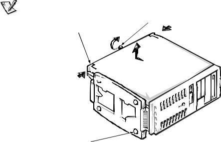
/RRVHQ WKH FRYHU PRXQWLQJ WKXPEVFUHZ VKRZQ LQ )LJXUH WKDW VHFXUHV WKH FRYHU WR WKH EDFN RI WKH FRPSXWHU
NOTE: The thumbscrew is captive and stays in the cover when loosened.
cover release |
cover-mounting thumbscrew |
latches (2) |
|
chassis foot 
)LJXUH 5HPRYLQJ WKH &RPSXWHU &RYHU 0LQL 7RZHU &KDVVLV
2-2 Dell Dimension XPS Dxxx Systems Reference and Troubleshooting Guide

)DFH WKH IURQW RI WKH FKDVVLV 3XVK LQ D FRYHU UHOHDVH ODWFK ZLWK \RXU WKXPE ZKLOH XVLQJ \RXU RWKHU KDQG WR SXOO XS WKH EDFN HGJH RI WKH FRPSXWHU QHDU WKH ODWFK XQWLO WKH FRYHU LV UHOHDVHG
Brace the chassis to prevent it from moving while you push in the cover release latch.
5HSHDW VWHS IRU WKH RWKHU FRYHU UHOHDVH ODWFK
6OLGH WKH FRYHU DSSUR[LPDWHO\ RQH LQFK WRZDUG WKH EDFN RI WKH FRP SXWHU 7KHQ OLIW WKH FRYHU RII WKH FRPSXWHU
:$51,1* 7R SUHYHQW FXWV NHHS \RXU KDQGV FOHDU RI WKH PHWDO HGJHV RQ WKH FKDVVLV DQG IDQ JXDUG DV \RX VOLGH EDFN WKH FRYHU
Replace the computer cover on a desktop or mini tower chassis as follows:
&KHFN DOO FDEOH FRQQHFWLRQV HVSHFLDOO\ WKRVH WKDW PLJKW KDYH FRPH ORRVH GXULQJ \RXU ZRUN )ROG FDEOHV DQG XQXVHG FRQQHFWRUV RXW RI WKH ZD\ VR WKDW WKH\ GR QRW FDWFK RQ WKH FRPSXWHU FRYHU RU LQWHUIHUH ZLWK DLUIORZ LQVLGH WKH FRPSXWHU
&KHFN WR VHH WKDW QR WRROV RU H[WUD SDUWV LQFOXGLQJ VFUHZV DUH OHIW LQVLGH WKH FRPSXWHU
3RVLWLRQ WKH FRYHU RQ WKH FKDVVLV DSSUR[LPDWHO\ RQH LQFK EDFN 6OLGH WKH FRYHU IRUZDUG XQWLO LW ORFNV LQWR SODFH
7LJKWHQ WKH FRYHU PRXQWLQJ WKXPEVFUHZ RQ WKH EDFN RI WKH FKDVVLV
,QVLGH <RXU &RPSXWHU
Figures 2-2 and 2-3 show the mini tower and desktop chassis with their covers removed as an aid in locating internal features and components.
When you look inside your computer, note the DC power cables coming from the power supply. These cables supply power to the system board, to internal drives, and to certain expansion cards that connect to external devices.
The flat ribbon cables are the interface cables for internal drives. An interface cable connects a drive to an interface connector on the system board or on an expansion card.
The system board—the large printed circuit board mounted vertically in the bottom half of the mini tower chassis or secured to the bottom of the desktop chassis—holds the computer’s control circuitry and other electronic components. Some hardware options are installed directly onto the system board.
Installing Upgrades on the System Board 2-3

chassis cooling fan
system board
filler brackets
chassis
bezel
card-guide assembly
(contains primary hard-disk drive)
power supply
DC power cables
diskette-drive interface cable
secondary hard-disk drive bracket
 drive cage
 drive bays


 power indicator
power button
hard-disk drive access indicator
reset button
)LJXUH ,QVLGH WKH 0LQL 7RZHU &KDVVLV
2-4 Dell Dimension XPS Dxxx Systems Reference and Troubleshooting Guide
 Loading...