


DCD0
Table of contents
 Loading...
www.dell.com | support.dell.com
Dell Precision™ Workstation 690
Quick Reference Guide
Model DCD0

Notes, Notices, and Cautions
NOTE: A NOTE indicates important information that helps you make better use of your computer.
NOTICE: A NOTICE indicates either potential damage to hardware or loss of data and tells you how to avoid
the problem.
CAUTION: A CAUTION indicates a potential for property damage, personal injury, or death.
Abbreviations and Acronyms
For a complete list of abbreviations and acronyms, see Glossary in your
User’s Guide
.
If you purchased a Dell™ n Series computer, any references in this document to Microsoft
®
Windows
®
operating systems are not applicable.
____________________
Information in this document is subject to change without notice.
© 2006 Dell Inc. All rights reserved.
Reproduction in any manner whatsoever without the written permission of Dell Inc. is strictly forbidden.
Trademarks used in this text: Dell, the DELL logo and Dell Precision are trademarks of Dell Inc.; Intel, Xeon, and Pentium are registered
trademarks of Intel Corporation; Microsoft and Windows are registered trademarks of Microsoft Corporation.
Other trademarks and trade names may be used in this document to refer to either the entities claiming the marks and names or their products.
Dell Inc. disclaims any proprietary interest in trademarks and trade names other than its own.
Model DCD0
January 2006 P/N PD050 Rev. A00

Contents 3
Contents
Finding Information . . . . . . . . . . . . . . . . . . . . . . . . . . . . . . . . 5
Setting Up Your Computer
. . . . . . . . . . . . . . . . . . . . . . . . . . . . . 9
About Your Computer
. . . . . . . . . . . . . . . . . . . . . . . . . . . . . . . 14
Front View
. . . . . . . . . . . . . . . . . . . . . . . . . . . . . . . . . . 15
Back View
. . . . . . . . . . . . . . . . . . . . . . . . . . . . . . . . . . 18
Back Panel Connectors
. . . . . . . . . . . . . . . . . . . . . . . . . . . 19
Inside View
. . . . . . . . . . . . . . . . . . . . . . . . . . . . . . . . . 21
System Board Components
. . . . . . . . . . . . . . . . . . . . . . . . . 22
Locating Your User’s Guide
. . . . . . . . . . . . . . . . . . . . . . . . . . . 24
Removing the Computer Cover
. . . . . . . . . . . . . . . . . . . . . . . . . . 24
Computer Stand
. . . . . . . . . . . . . . . . . . . . . . . . . . . . . . . . . 27
Attaching the Computer Stand
. . . . . . . . . . . . . . . . . . . . . . . 27
Removing the Computer Stand
. . . . . . . . . . . . . . . . . . . . . . . 29
Caring for Your Computer
. . . . . . . . . . . . . . . . . . . . . . . . . . . . 29
Solving Problems
. . . . . . . . . . . . . . . . . . . . . . . . . . . . . . . . 29
Troubleshooting Tips
. . . . . . . . . . . . . . . . . . . . . . . . . . . . 29
Resolving Software and Hardware Incompatibilities
. . . . . . . . . . . 30
Using Microsoft
®
Windows
®
XP System Restore . . . . . . . . . . . . . 30
Using the Last Known Good Configuration
. . . . . . . . . . . . . . . . . 31
Dell Diagnostics
. . . . . . . . . . . . . . . . . . . . . . . . . . . . . . . 32
Before you start testing
. . . . . . . . . . . . . . . . . . . . . . . . . . . 33
Beep Codes
. . . . . . . . . . . . . . . . . . . . . . . . . . . . . . . . . . . . 33
Error Messages
. . . . . . . . . . . . . . . . . . . . . . . . . . . . . . . 35
Diagnostic Lights
. . . . . . . . . . . . . . . . . . . . . . . . . . . . . . . . . 35
Diagnostic Light Codes Before POST
. . . . . . . . . . . . . . . . . . . . 35
Diagnostic Light Codes During POST
. . . . . . . . . . . . . . . . . . . . 37
Frequently Asked Questions
. . . . . . . . . . . . . . . . . . . . . . . . . . . 42
Index . . . . . . . . . . . . . . . . . . . . . . . . . . . . . . . . . . . . . . . . . 43

4 Contents
Quick Reference Guide 5
Finding Information
NOTE: Some features or media may be optional and may not ship with your computer. Some features or media
may not be available in certain countries.
NOTE: Additional information may ship with your computer.
What Are You Looking For? Find It Here
• A diagnostic program for my computer
• Drivers for my computer
• My computer documentation
• My device documentation
• Desktop System Software (DSS)
Drivers and Utilities CD (also known as Resource CD)
Documentation and
drivers are already
installed on your
computer. You can use
the CD to reinstall drivers,
run the Dell Diagnostics
or access your
documentation. Readme
files may be included on
your CD to provide last-
minute updates about
technical changes to your computer or advanced technical-
reference material for technicians or experienced users.
NOTE: Drivers and documentation updates can be found
at support.dell.com.
• How to set up my computer
• How to care for my computer
• Basic troubleshooting information
• How to run the Dell™ Diagnostics
• Error codes and diagnostic lights
• How to remove and install parts
• How to open my computer cover
Quick Reference Guide
NOTE: This document is available as a PDF at
support.dell.com.
6 Quick Reference Guide
• Warranty information
• Terms and Conditions (U.S. only)
• Safety instructions
• Regulatory information
• Ergonomics information
• End User License Agreement
Dell™ Product Information Guide
• How to remove and replace parts
• Specifications
• How to configure system settings
• How to troubleshoot and solve problems
User’s Guide
Microsoft
®
Windows
®
XP Help and Support Center
1
Click the Start button and click
Help and Support
2
Click User’s and system guides and click
User’s Guide
The User’s Guide is also available on the Drivers and
Utilities CD.
• Service Tag and Express Service Code
• Microsoft Windows License Label
Service Tag and Microsoft
®
Windows
®
License
These labels are located on your computer.
• Use the Service Tag to
identify your computer
when you use
support.dell.com
or
contact technical
support.
• Enter the Express
Service Code to direct your call when contacting technical
support.
What Are You Looking For? Find It Here

Quick Reference Guide 7
• Solutions — Troubleshooting hints and tips, articles
from technicians, and online courses, frequently asked
questions
• Community — Online discussion with other Dell
customers
• Upgrades — Upgrade information for components,
such as memory, the hard drive, and the operating
system
• Customer Care — Contact information, service call
and order status, warranty, and repair information
• Service and support — Service call status and support
history, service contract, online discussions with
technical support
• Reference — Computer documentation, details on my
computer configuration, product specifications, and
white papers
• Downloads — Certified drivers, patches, and software
updates
• Desktop System Software (DSS)— If you reinstall the
operating system for your computer, you should reinstall
the DSS utility prior to installing any of the drivers. DSS
provides critical updates for your operating system and
support for Dell™ 3.5-inch USB floppy drives, optical
drives, and USB devices. DSS is necessary for correct
operation of your Dell computer. The software
automatically detects your computer and operating
system and installs the updates appropriate for your
configuration.
Dell Support Website — support.dell.com
NOTE: Select your region or business segment to view
the appropriate support site.
NOTE: Corporate, government, and education customers
can also use the customized Dell Premier support website at
premier.support.dell.com. The website may not be available
in all regions.
• How to use Windows XP
• How to work with programs and files
• Documentation for devices (such as modem)
Windows Help and Support Center
1
Click the
Start
button and click
Help and Support
.
2
Type a word or phrase that describes your problem
and click the arrow icon.
3
Click the topic that describes your problem.
4
Follow the instructions on the screen.
What Are You Looking For? Find It Here

8 Quick Reference Guide
• How to reinstall my operating system
Operating System CD
The operating system is
already installed on your
computer. To reinstall your
operating system, use the
Operating System CD. See
your User’s Guide for
instructions. After you
reinstall your operating
system, use the Drivers and
Utilities CD (ResourceCD)
to reinstall drivers for the
devices that came with your computer. Your operating
system product key label is located on your computer.
NOTE: The color of your CD varies based on the operating
system you ordered.
NOTE: The Operating System CD may be optional and may
not ship with your computer.
• How to use Linux
• E-mail discussions with users of Dell Precision™
products and the Linux operating system
• Additional information regarding Linux
and my Dell Precision computer
Dell Supported Linux Sites
• Linux.dell.com
• Lists.us.dell.com/mailman/listinfo/linux-precision
What Are You Looking For? Find It Here

Quick Reference Guide 9
Setting Up Your Computer
CAUTION: Before you begin any of the procedures in this section, follow the safety instructions
in the Product Information Guide.
You must complete all steps to properly set up your computer.
1
Connect the keyboard and the mouse.
2
NOTICE: Do not connect a modem cable to
the network adapter. Voltage from telephone
communications can damage the network adapter.
NOTE: If your computer has a network card installed,
connect the network cable to the card.
Connect the modem or the network cable.
10 Quick Reference Guide
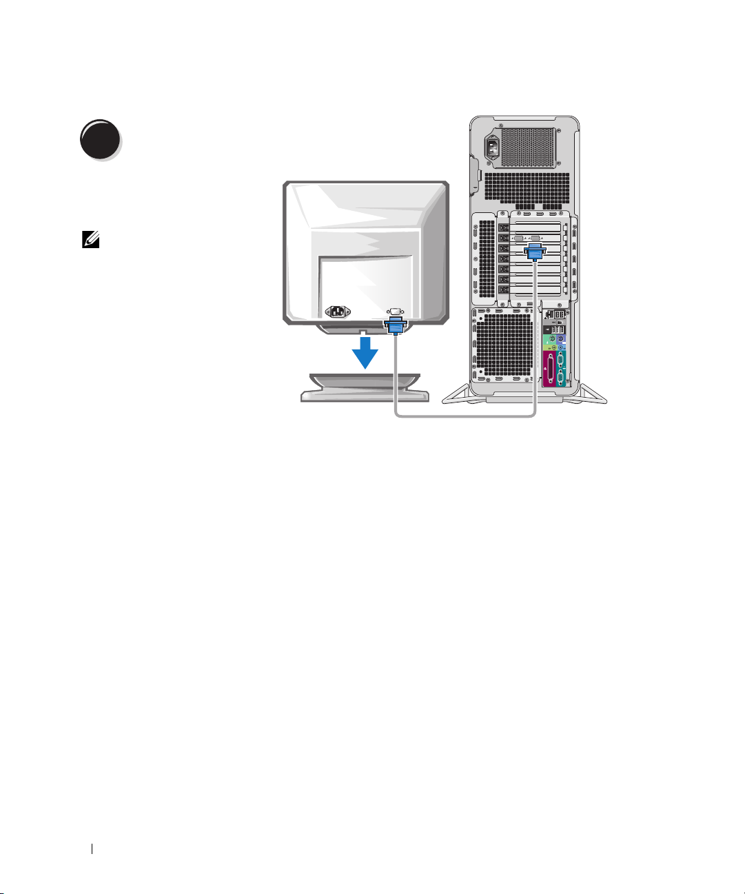
3
Depending on your graphics
card, you can connect your
monitor in various ways.
NOTE: You may need to use
the provided adapter or
cable to connect your
monitor to the computer.
Connect the monitor.
Quick Reference Guide 11
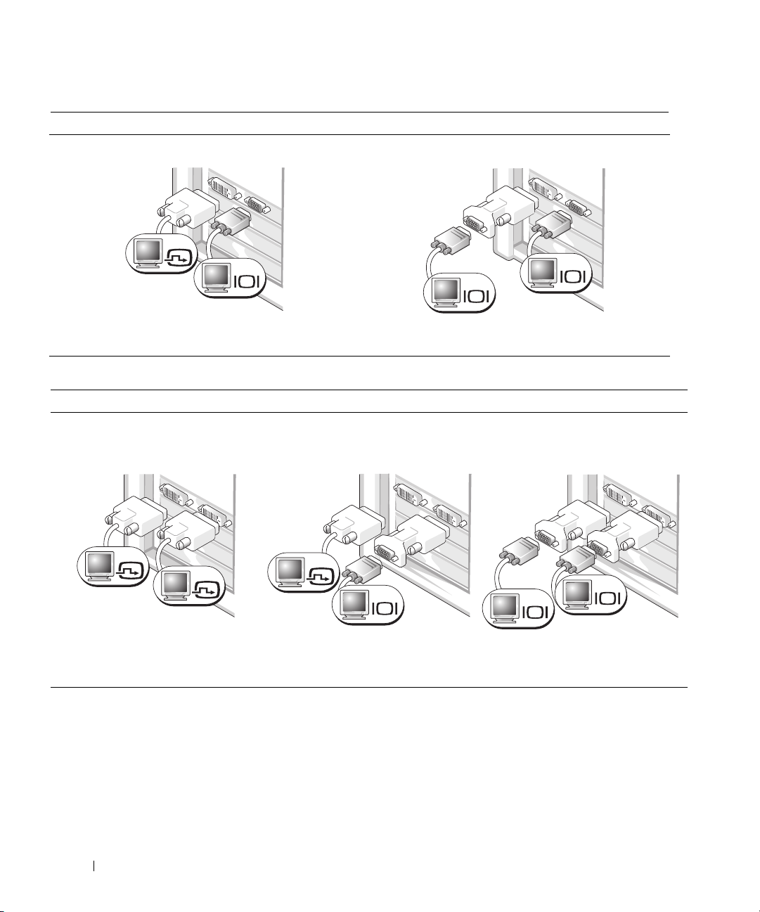
The dual-monitor cable is color-coded; the blue connector is for the primary monitor, and the black
connector is for the second monitor. To enable dual-monitor support, both monitors must be attached
to the computer when you start the computer.
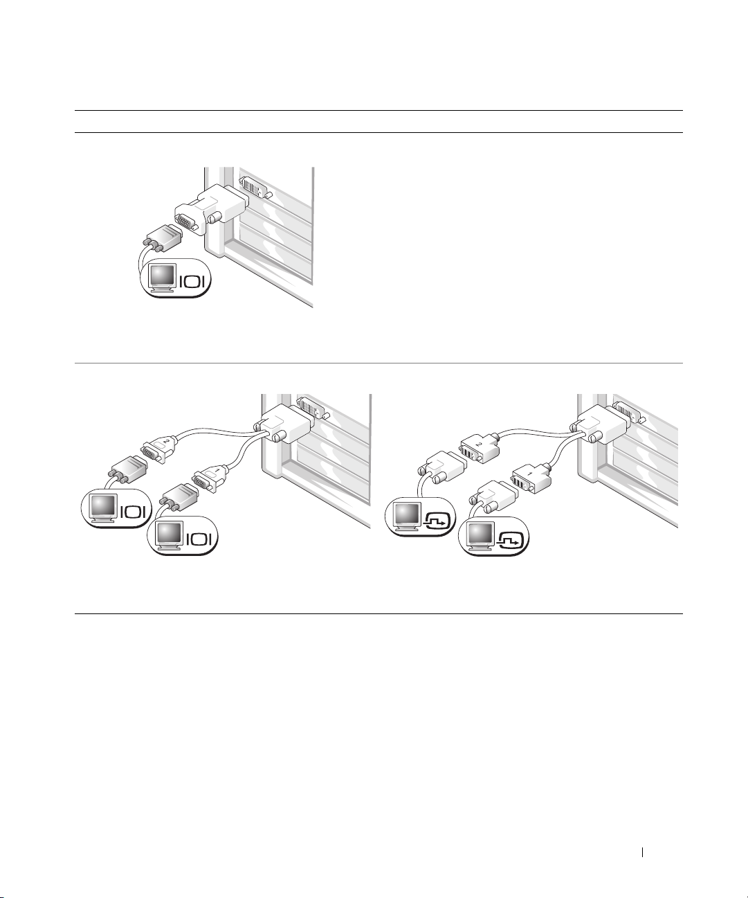
For single- and dual-monitor capable cards with a single connector
One VGA adapter:
Use the VGA adapter when you have a single-monitor
graphics card and you want to connect your computer
to a VGA monitor.
Dual VGA Y cable adapter:
Use the appropriate Y cable when your graphics card has a
single connector and you want to connect your computer
to one or two VGA monitors.
Dual DVI Y cable adapter:
Use the appropriate Y cable when your graphics card has a
single connector and you want to connect your computer
to one or two DVI monitors.
VGA
VGA
VGA
DVI
DVI
12 Quick Reference Guide
For dual-monitor capable cards with one DVI connector and one VGA connector
One DVI connector and one VGA connector:
Use the appropriate connector(s) when you want
to connect your computer to one or two monitors.
Two VGA connectors with one VGA adapter:
Use the VGA adapter when you want to connect
your computer to two VGA monitors.
VGA
DVI
VGA
VGA
For dual-monitor capable cards with two DVI connectors
Two DVI connectors:
Use the DVI connectors to connect
your computer to one or two DVI
monitors.
Two DVI connectors with one VGA
adapter:
Use the VGA adapter to connect a
VGA monitor to one of the DVI
connectors on your computer
Two DVI connectors with two VGA
adapters:
Use two VGA adapters to connect
two VGA monitors to the DVI
connectors on your computer.
DVI
DVI
DVI
VGA
VGA
VGA
Quick Reference Guide 13
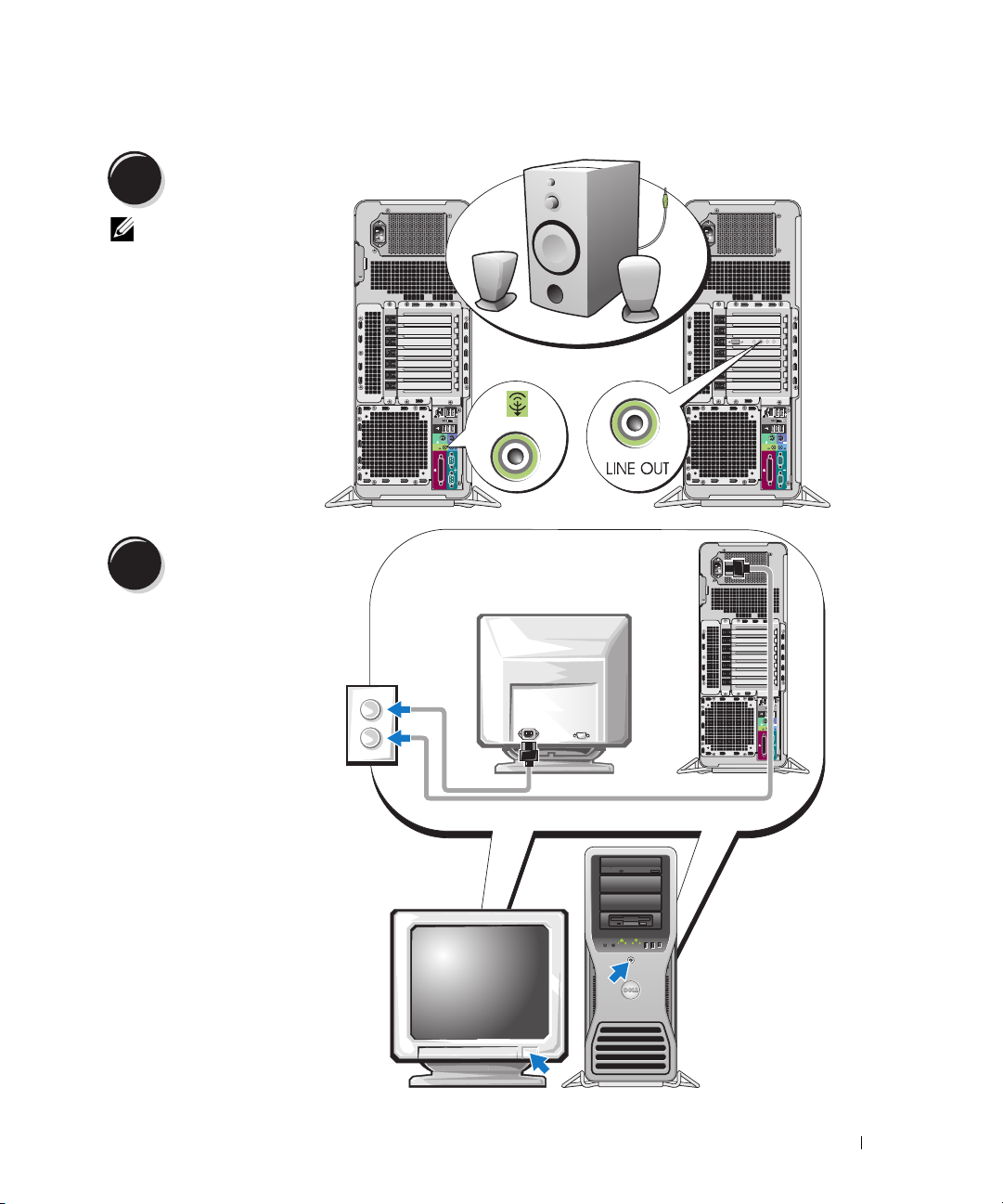
4
NOTE: If your
computer has a sound
card installed, connect
the speakers to the
card.
Connect the speakers.
5
Connect the power
cables and turn on the
computer and monitor.

14 Quick Reference Guide
Before you install any devices or software that did not come with your computer, read the documentation
that came with the software or device or contact the vendor to verify that the software or device is
compatible with your computer and operating system.
You have now completed the setup for your computer.
About Your Computer
CAUTION: Your computer is heavy (it has an approximate minimum weight of 55 lbs) and can be difficult to
maneuver. Seek assistance before attempting to lift, move, or tilt it; this computer requires a two-man lift.
Always lift correctly to avoid injury; avoid bending over while lifting. See your Product Information Guide
for other important safety information.
CAUTION: Before setting your computer upright, install the computer stand. Failure to install the stand before
setting the computer upright could cause the computer to tip over, potentially resulting in bodily injury or damage
to the computer.
6
Install additional software or devices.
Quick Reference Guide 15
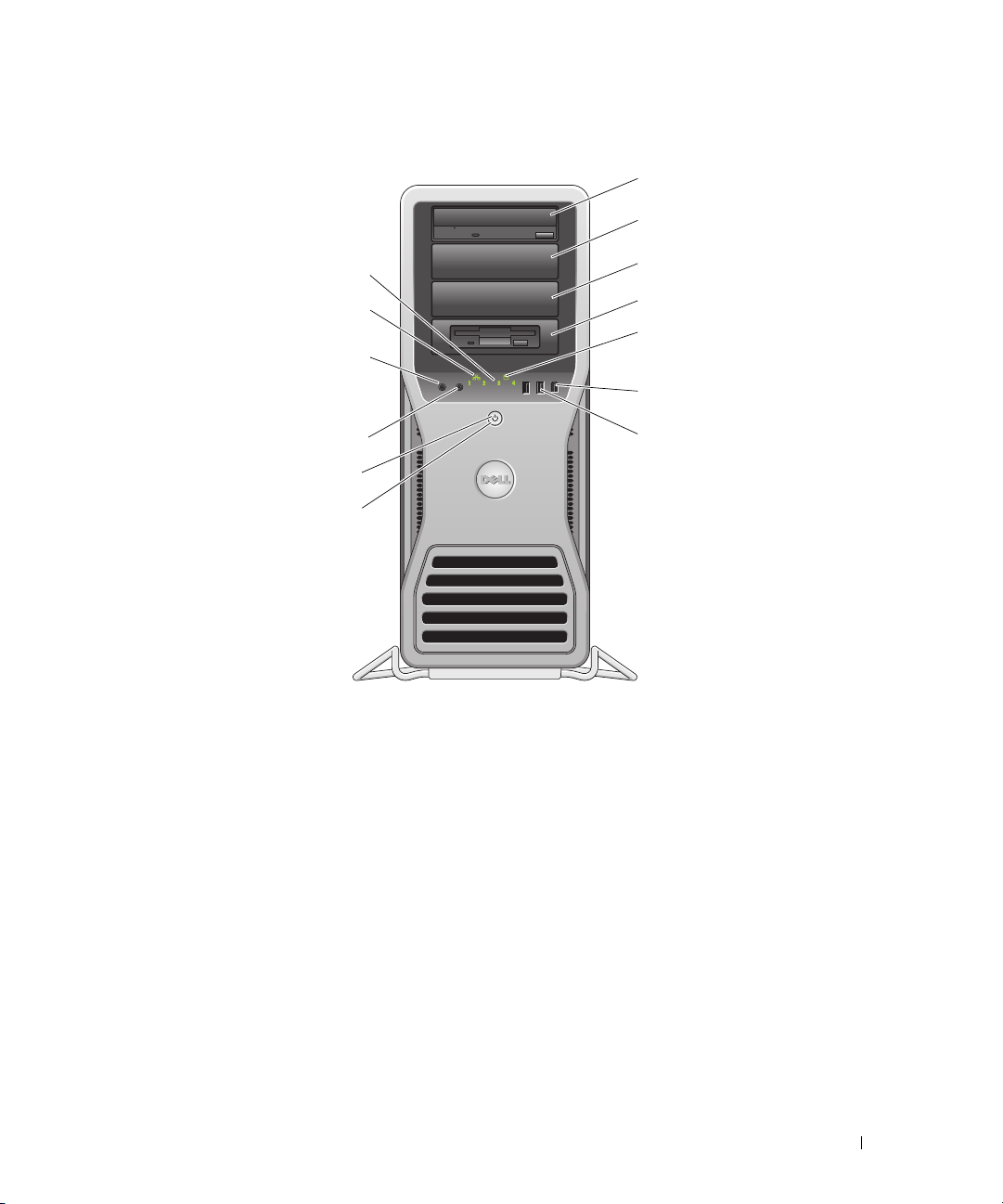
Front View
1
2
3
5
6
8
9
10
11
12
13
4
7

16 Quick Reference Guide
1-3 5.25-inch drive bays Can hold a CD/DVD drive, or a Media Card Reader, floppy drive, or SATA hard
drive in a 5.25-inch drive bay carrier.
NOTE: The drive carriers are only for use in the 5.25-inch drive bays. The
floppy-drive/ Media Card Reader and hard-drive carriers are not interchangeable.
4 5.25-inch drive bay with
special 3.5-inch drive
panel plate
Can hold a CD/DVD drive, or a Media Card Reader, floppy drive, or SATA hard
drive in a 5.25-inch drive bay carrier. The drive-panel plate shown here is only for
use with a floppy drive or Media Card Reader; it can be installed in front of any of
the four 5.25-inch drive bays. For more information, see your User’s Guide.
NOTE: The drive carriers are only for use in the 5.25-inch drive bays. The floppy drive/
Media Card Reader and hard drive carriers are not interchangeable.
5 hard-drive activity light The hard drive light is on when the computer reads data from or writes data to the
hard drive. The light might also be on when a device such as your CD player is
operating.
6 IEEE 1394 connector Use the IEEE 1394 connector for high-speed data devices such as digital video
cameras and external storage devices.

Quick Reference Guide 17
7 USB 2.0 connectors (2) Use the front USB connectors for devices that you connect occasionally, such as
flash memory keys, cameras, or bootable USB devices (see your User’s Guide for
more information).
It is recommended that you use the back USB connectors for devices that typically
remain connected, such as printers and keyboards.
8 power button Press to turn on the computer.
NOTICE: To avoid losing data, do not use the power button to turn off the
computer. Instead, perform an operating system shutdown.
NOTE: The power button can also be used to wake the system or to place it into
a power-saving state. See your User’s Guide for more information.
9 power light The power light illuminates and blinks or remains solid to indicate different states:
• No light — The computer is turned off or in a hibernation mode.
• Steady green — The computer is in a normal operating state.
• Blinking green — The computer is in a power-saving state.
• Blinking or solid amber — See "Power Problems" in your
User’s Guide
.
To exit from a power-saving state, press the power button or use the keyboard or
the mouse if it is configured as a wake device in the Windows Device Manager.
For more information about sleep states and exiting from a power-saving state,
see your User’s Guide.
See "Diagnostic Lights" on page 35 for a description of light codes that can help
you troubleshoot problems with your computer.
10 microphone connector Use the microphone connector to attach a personal computer microphone
for voice or musical input into a sound or telephony program.
11 headphone connector Use the headphone connector to attach headphones.
12 network link light The network link light is on when a good connection exists between a 10-Mbps,
100-Mbps, or 1000-Mbps (or 1-Gbps) network and the computer.
13 diagnostic lights (4) Use these lights to help you troubleshoot a computer problem based on the
diagnostic code. For more information, see "Diagnostic Lights" on page 35.

18 Quick Reference Guide
Back View
1
2
3
1 power connector Insert the power cable. The appearance of this connector may differ from what is
pictured here.
2 card slots Access connectors for any installed PCI, PCI-X, or PCI Express cards.
NOTE: The center five connector slots support full-length cards: one PCI, one PCI
express x16, one PCI express x8 (wired as x4), and two PCI-X slots; the connector
slots at the top and at the bottom support half-length cards: two PCI express x8 slots
(wired as x4).
3 back panel connectors Plug serial, USB, and other devices into the
appropriate connector
(see "Back Panel Connectors" on page 19).
Quick Reference Guide 19
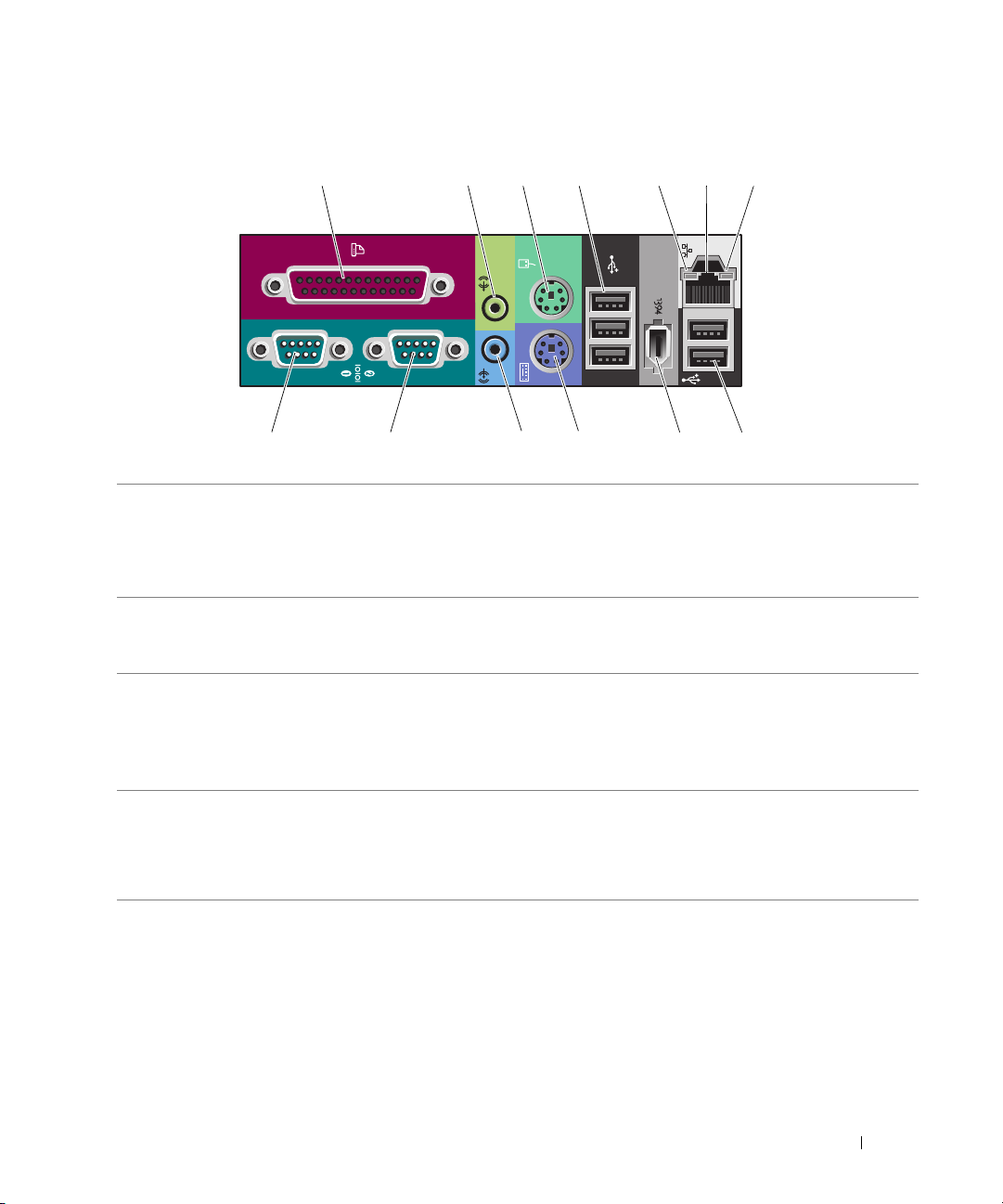
Back Panel Connectors
1 234 6
13 12 11 10 89
57
1 parallel connector Connect a parallel device, such as a printer, to the parallel connector. If you have
a USB printer, plug it into a USB connector.
NOTE: The integrated parallel connector is automatically disabled if the computer
detects an installed card containing a parallel connector configured to the same
address. For more information, see your User’s Guide.
2 line-out/ headphone
connector
Use the green line-out connector to attach headphones and most speakers with
integrated amplifiers.
On computers with a sound card, use the connector on the card.
3 mouse connector Plug a standard mouse into the green mouse connector. Turn off the computer
and any attached devices before you connect a mouse to the computer. If you have
a USB mouse, plug it into a USB connector.
If your computer is running the Microsoft
®
Windows
®
XP operating system,
the necessary mouse drivers have been installed on your hard drive.
4 USB 2.0 connectors (3) It is recommended that you use the front USB connectors for devices that you
connect occasionally, such as flash memory keys, cameras, or bootable USB
devices.
Use the back USB connectors for devices that typically remain connected,
such as printers and keyboards.

20 Quick Reference Guide
5 link integrity light
• Green — A good connection exists between a 10-Mbps network and the
computer.
• Orange — A good connection exists between a 100-Mbps network and the
computer.
• Yellow — A good connection exists between a 1000-Mbps (or 1-Gbps) network
and the computer.
• Off — The computer is not detecting a physical connection to the network.
6 network adapter
connector
To attach your computer to a network or broadband device, connect one end
of a network cable to either a network jack or your network or broadband device.
Connect the other end of the network cable to the network adapter connector
on your computer. A click indicates that the network cable has been securely
attached.
NOTE: Do not plug a telephone cable into the network connector.
On computers with an additional network connector card, use the connectors
on the card and on the back of the computer when setting up multiple network
connections (such as a separate intra- and extranet).
It is recommended that you use Category 5 wiring and connectors for your
network. If you must use Category 3 wiring, force the network speed to 10 Mbps
to ensure reliable operation.
7 network activity light Flashes a yellow light when the computer is transmitting or receiving network
data. A high volume of network traffic may make this light appear to be in a steady
"on" state.
8 USB 2.0 connectors (2) It is recommended that you use the front USB connectors for devices that you
connect occasionally, such as flash memory keys, cameras, or bootable USB
devices.
Use the back USB connectors for devices that typically remain connected,
such as printers and keyboards.
9 IEEE 1394 connector Use the IEEE 1394 connector for high-speed data devices such as digital video
cameras and external storage devices.
10 keyboard connector If you have a standard keyboard, plug it into the purple keyboard connector.
If you have a USB keyboard, plug it into a USB connector.
11 line-in connector Use the blue line-in connector to attach a record/playback device such as a cassette
player, CD player, or VCR.
On computers with a sound card, use the connector on the card.
12 serial connector Connect a serial device, such as a handheld device, to the serial port. If necessary,
the address for this port can be modified through System Setup (see your User’s
Guide for more information).
13 serial connector Connect a serial device, such as a handheld device, to the serial port. If necessary,
the address for this port can be modified through System Setup (see your User’s
Guide for more information).
Quick Reference Guide 21
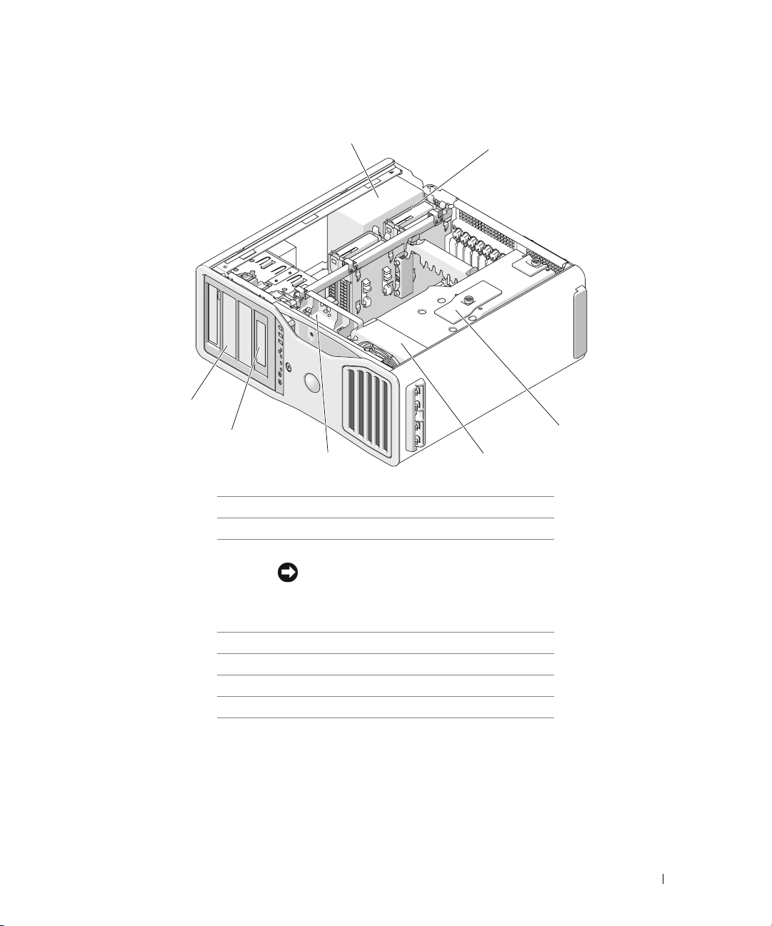
Inside View
1 power supply
2 hard drive bay
3 memory shroud
NOTICE: The memory shroud holds the
(optional) memory riser cards in place; its
thumbscrews must be sufficiently tight in order
to secure the risers and to avoid damage.
4 front fan
5 card fan
6 5.25-inch drive bay with 3.5-inch drive panel plate
7 5.25-inch drive bay
1
2
3
6
7
45
22 Quick Reference Guide
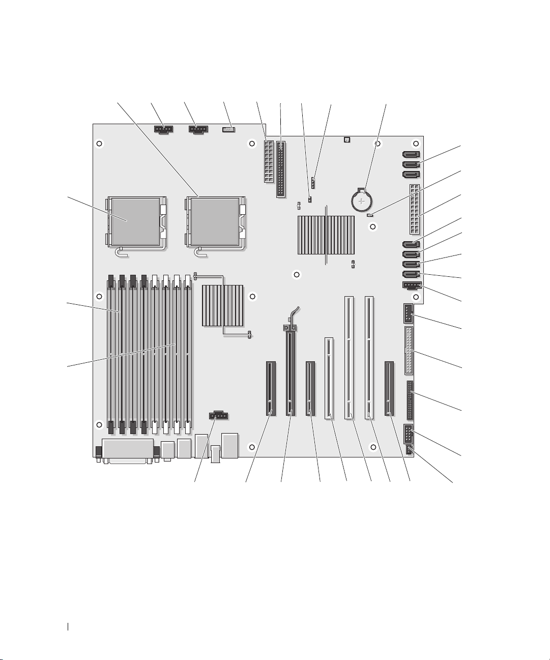
System Board Components
2 3456 9
26272829
31
33
1 8
10
12
14
15
16
17
18
19
21
11
7
22
20
232425
13
30
32

Quick Reference Guide 23
1 secondary processor connector (CPU_1) 18 FlexBay connector (USB)
2 front fan connector (FAN_FRONT) 19 floppy drive (DSKT)
3 card cage fan connector (FAN_CCAG) 20 front panel connector (FRONTPANEL)
4 internal speaker connector (INT_SPKR) 21 front panel 1394 connector (FP1394)
5 power connector (POWER2) 22 chassis intrusion header (INTRUDER)
6 IDE drive connector (IDE) 23 PCI-Express x8 card slot, wired as x4
(SLOT7_PCIE)
7 password jumper (PSWD) 24 PCI-X card slot (SLOT6_PCIX)
8 auxiliary hard-drive LED connector
(AUX_LED)
25 PCI-X card slot (SLOT5_PCIX)
9 battery socket (BATTERY) 26 PCI card slot (SLOT4_PCI)
NOTE: This slot is not available in the dual-
graphics configuration
10 SATA connectors
(SATA_0, SATA_1, SATA_2)
27 PCI-Express x8 card slot, wired as x4
(SLOT3_PCIE)
NOTE: In the dual-graphics configuration, this slot
is replaced by a x16 slot on the graphics riser.
It holds a graphic card.
11 RTC reset jumper (RTCRST) 28 PCI-Express x16 card slot (SLOT2_PCIE)
NOTE: This slot is not available in the dual-
graphics configuration
12 main power connector (POWER1) 29 PCI-Express x8 card slot, wired as x4
(SLOT1_PCIE)
NOTE: In the dual-graphics configuration, this slot
is replaced by a x16 slot on the graphics riser. It
holds a graphics card.
13 hard drive connector (HDD_3) 30 memory fan connector (FAN_MEM)
14 hard drive connector (HDD_2) 31 white memory module connectors (DIMM_1-4)
support memory modules or memory module
risers
15 hard drive connector (HDD_1) 32 black memory module connectors (DIMM_5-8)
support memory modules only when no memory
riser cards are installed; otherwise these must be
left empty
16 hard drive connector (HDD_0) 33 primary processor connector (CPU_0)
17 hard drive fan (FAN_HDD)

24 Quick Reference Guide
Cable Colors
Locating Your User’s Guide
Your
User’s Guide
contains additional information about your computer such as:
• Technical specifications
• Front and back views of your computer, including all of the available connectors
• Inside views of your computer, including a detailed graphic of the system board and the connectors
• Instructions for cleaning your computer
• Information on software features, such as Legacy Select Technology control, using a password, and
system setup options
• Tips and information for using the Microsoft Windows XP operating system
• Instructions for removing and installing parts, including memory, cards, drives, the microprocessor,
and the battery
• Information for troubleshooting various computer problems
• Instructions for using the Dell Diagnostics and reinstalling drivers
• Information on how to contact Dell
You can access the
User’s Guide
from your hard drive or the Dell Support website at
support.dell.com
.
Removing the Computer Cover
CAUTION: Before you begin any of the procedures in this section, follow the safety instructions in the Product
Information Guide.
CAUTION: To guard against electrical shock, always unplug your computer from the electrical outlet before
removing the cover.
CAUTION: Your computer is heavy (it has an approximate minimum weight of 55 lbs) and can be difficult to
maneuver. Seek assistance before attempting to lift, move, or tilt it; this computer requires a two-man lift. Always
lift correctly to avoid injury; avoid bending over while lifting. See your Product Information Guide for other
important safety information.
CAUTION: The computer stand should be installed at all times to ensure maximum system stability. Failure to
install the stand could result in the computer tipping over, potentially resulting in bodily injury or damage to
the computer.
Device Color
Hard drive (with on-board controller) blue cable
Floppy drive black pull-tab
CD/DVD drive orange pull-tab

Quick Reference Guide 25
NOTICE: To prevent static damage to components inside your computer, discharge static electricity from your
body before you touch any of your computer’s electronic components. You can do so by touching an unpainted
metal surface on the computer.
1
Follow the procedures in "Before You Begin" in the
User’s Guide
.
NOTICE: Opening the computer cover while the computer is running could result in a shutdown without warning
and a loss of data in open programs. The computer cooling system cannot function properly while the cover is
removed.
2
If you have installed a security cable, remove it from the security cable slot.
3
Carefully, with the help of an assistant, remove the computer stand (see "Removing the Computer
Stand").
CAUTION: Your computer is heavy (it has an approximate minimum weight of 55 lbs) and can be difficult to
maneuver. Seek assistance before attempting to lift, move, or tilt it; this computer requires a two-man lift. Always
lift correctly to avoid injury; avoid bending over while lifting. See your Product Information Guide for other
important safety information.
CAUTION: The computer stand should be installed at all times to ensure maximum system stability. Failure to
install the stand could result in the computer tipping over, potentially resulting in bodily injury or damage to the
computer.
NOTICE: Ensure that you are working on a level, protected surface to avoid scratching either the computer or the
surface on which it is resting.
4
Carefully, with the help of an assistant, lower your computer down to a flat surface with the cover
facing up.
5
Pull back the cover latch release.
NOTICE: Ensure that sufficient space exists to support the removed cover—at least 30 cm (1 ft) of desk top space.

26 Quick Reference Guide
6
Locate the three hinge tabs on the edge of the computer.
7
Grip the sides of the computer cover and pivot the cover up, using the hinges as leverage points.
8
Release the cover from the hinge tabs and set it aside in a secure location.
NOTICE: The computer cooling system cannot function properly while the computer cover is not installed.
Do not attempt to boot the computer before reinstalling the computer cover.
1 cover latch release
2 computer cover
3 cover hinges
1
3
2

Quick Reference Guide 27
Computer Stand
CAUTION: Your computer is heavy (it has an approximate minimum weight of 55 lbs) and can be difficult to
maneuver. Seek assistance before attempting to lift, move, or tilt it; this computer requires a two-man lift. Always
lift correctly to avoid injury; avoid bending over while lifting. See your Product Information Guide for other
important safety information.
CAUTION: The computer stand should be installed at all times to ensure maximum system stability. Failure to
install the stand could result in the computer tipping over, potentially resulting in bodily injury or damage to
the computer.
CAUTION: Before you begin any of the procedures in this section, follow the safety instructions in the Product
Information Guide.
CAUTION: To guard against electrical shock, always unplug your computer from the electrical outlet before
removing the cover.
NOTICE: To prevent static damage to components inside your computer, discharge static electricity from your
body before you touch any of your computer’s electronic components. You can do so by touching an unpainted
metal surface on the computer.
Attaching the Computer Stand
CAUTION: Your computer is heavy (it has an approximate minimum weight of 55 lbs) and can be difficult to
maneuver. Seek assistance before attempting to lift, move, or tilt it; this computer requires a two-man lift. Always
lift correctly to avoid injury; avoid bending over while lifting. See your Product Information Guide for other
important safety information.
CAUTION: The computer stand should be installed at all times to ensure maximum system stability. Failure to
install the stand could result in the computer tipping over, potentially resulting in bodily injury or damage to
the computer.
1
Follow the procedures in "Before You Begin" in the
User’s Guide
.
2
If you have installed a security cable, remove it from the security cable slot.
3
Set the stand on the ground in front of the computer, so that the front and the back of the stand touch
the ground.
If the front and the back of the stand point up toward the ceiling, the stand is upside down.
4
Ensure that the alignment guide faces the computer.
If the alignment guide points away from the computer, the stand is backwards.
28 Quick Reference Guide
5
Align the center of the stand with the center of the computer.
6
Carefully, with the help of an assistant, tilt the computer backwards slightly- just high enough to slide
the stand beneath it.
7
Slide the rear of the stand into the rear foot of the computer, and ensure that the alignment guide
slides into place.
8
Center the front bar of the stand in the corresponding notch in the front foot of the computer.
9
Carefully set the computer back down; the front bar of the stand should snap into place under
the weight of the computer.
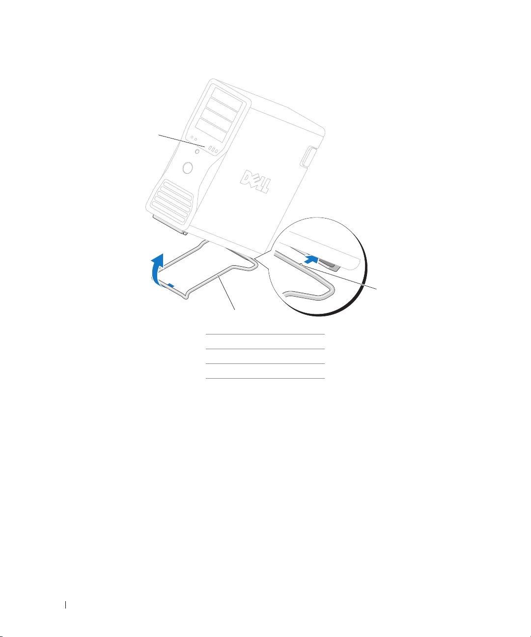
2
1
3
1 computer
2 computer stand
3 alignment guide

Quick Reference Guide 29
Removing the Computer Stand
CAUTION: Your computer is heavy (it has an approximate minimum weight of 55 lbs) and can be difficult to
maneuver. Seek assistance before attempting to lift, move, or tilt it; this computer requires a two-man lift. Always
lift correctly to avoid injury; avoid bending over while lifting. See your Product Information Guide for other
important safety information.
CAUTION: The computer stand should be installed at all times to ensure maximum system stability. Failure to
install the stand could result in the computer tipping over, potentially resulting in bodily injury or damage to
the computer.
1
Follow the procedures in "Before You Begin" in the
User’s Guide
.
2
Carefully, with the help of an assistant, tip the computer back at a very slight angle from the ground.
3
Pull the front of the computer stand down towards the ground, to release it from the front of the
computer.
4
Pull the computer stand toward the front of the computer until the stand is free.
Caring for Your Computer
To help maintain your computer, follow these suggestions:
• To avoid losing or corrupting data, never turn off your computer when the hard drive light is on.
• Schedule regular virus scans using virus software.
• Manage hard drive space by periodically deleting unnecessary files and defragmenting the drive.
• Back up files on a regular basis.
• Periodically clean your monitor screen, mouse, and keyboard (see your
User’s Guide
for more
information).
Solving Problems
Troubleshooting Tips
Perform the following checks when you troubleshoot your computer:
• If you added or removed a part before the problem started, review the installation procedures
and ensure that the part is correctly installed.
• If a peripheral device does not work, ensure that the device is properly connected.
• If an error message appears on the screen, write down the exact message. The message may help
technical support personnel diagnose and fix the problem(s).
• If an error message occurs in a program, see the program’s documentation.
• If the recommended action in the troubleshooting section is to see a section in your
User’s Guide
,
go to
support.dell.com
(on another computer if necessary) to access your
User’s Guide.

30 Quick Reference Guide
Resolving Software and Hardware Incompatibilities
If a device is either not detected during the operating system setup or is detected but incorrectly configured,
you can use the Hardware Troubleshooter to resolve the incompatibility.
To resolve incompatibilities using the Hardware Troubleshooter:
1
Click the
Start
button and click
Help and Support
.
2
Ty p e
hardware troubleshooter
in the
Search
field and click the arrow to start the search.
3
Click
Hardware Troubleshooter
in the
Search Results
list.
4
In the
Hardware Troubleshooter
list, click
I need to resolve a hardware conflict on my computer
,
and click
Next
.
Using Microsoft
®
Windows
®
XP System Restore
The Microsoft Windows XP operating system provides System Restore to allow you to return your computer
to an earlier operating state (without affecting data files) if changes to the hardware, software, or other
system settings have left the computer in an undesirable operating state. See the Windows Help and
Support Center (see "Finding Information" on page 5) for information about using System Restore.
NOTICE: Make regular backups of your data files. System Restore does not monitor your data files or recover
them.
Creating a Restore Point
1
Click the
Start
button and click
Help and Support
.
2
Click
System Restore
.
3
Follow the instructions on the screen.
Restoring the Computer to an Earlier Operating State
NOTICE: Before you restore the computer to an earlier operating state, save and close any open files and exit any
open programs. Do not alter, open, or delete any files or programs until the system restoration is complete.
1
Click the
Start
button, point to
All Programs
→
Accessories
→
System Tools
, and then click
System
Restore
.
2
Ensure that
Restore my computer to an earlier time
is selected and click
Next
.
3
Click a calendar date to which you want to restore your computer.
The
Select a Restore Point
screen provides a calendar that allows you to see and select restore points.
All calendar dates with available restore points appear in boldface type.
4
Select a restore point and click
Next
.
If a calendar date has only one restore point, then that restore point is automatically selected. If two
or more restore points are available, click the restore point that you prefer.
Loading...