


 Loading...
Chromebook 11 3180
Disassembly and Reassembly Guide - For use by Dell Certi€ed Technicians only
Regulatory Model: P26T
Regulatory Type: P26T002
Notes, cautions, and warnings

 NOTE: A NOTE indicates important information that helps you make better use of your product.

 CAUTION: A CAUTION indicates either potential damage to hardware or loss of data and tells you how to avoid the problem.
 WARNING: A WARNING indicates a potential for property damage, personal injury, or death.
© 2017 Dell Inc. or its subsidiaries. All rights reserved. Dell, EMC, and other trademarks are trademarks of Dell Inc. or its subsidiaries. Other trademarks may be trademarks of their respective owners.
2017 - 02
Rev. A00

Contents
1 Working on your computer............................................................................................................................. |
6 |
Safety instructions............................................................................................................................................................. |
6 |
Before working inside your computer.............................................................................................................................. |
6 |
After working inside your computer................................................................................................................................. |
7 |
2 Removing and installing components............................................................................................................. |
8 |
Recommended tools.......................................................................................................................................................... |
8 |
microSD card...................................................................................................................................................................... |
8 |
Removing microSD card.............................................................................................................................................. |
8 |
Installing microSD card................................................................................................................................................ |
8 |
Base cover.......................................................................................................................................................................... |
8 |
Removing base cover.................................................................................................................................................. |
8 |
Installing base cover................................................................................................................................................... |
10 |
Battery............................................................................................................................................................................... |
10 |
Removing battery....................................................................................................................................................... |
10 |
Installing battery.......................................................................................................................................................... |
10 |
Keyboard............................................................................................................................................................................. |
11 |
Removing keyboard..................................................................................................................................................... |
11 |
Installing keyboard...................................................................................................................................................... |
12 |
Audio board........................................................................................................................................................................ |
13 |
Removing audio board................................................................................................................................................ |
13 |
Installing audio board.................................................................................................................................................. |
13 |
Power connector port...................................................................................................................................................... |
14 |
Removing power connector port.............................................................................................................................. |
14 |
Installing power connector port................................................................................................................................ |
14 |
Speaker.............................................................................................................................................................................. |
15 |
Removing speaker...................................................................................................................................................... |
15 |
Installing speakers....................................................................................................................................................... |
16 |
Touchpad panel................................................................................................................................................................. |
16 |
Removing touchpad................................................................................................................................................... |
16 |
Installing touchpad...................................................................................................................................................... |
18 |
System board.................................................................................................................................................................... |
18 |
Removing system board............................................................................................................................................ |
18 |
Installing system board............................................................................................................................................... |
21 |
Display assembly............................................................................................................................................................... |
21 |
Removing display assembly....................................................................................................................................... |
21 |
Installing display assembly......................................................................................................................................... |
23 |
Display bezel..................................................................................................................................................................... |
24 |
Removing display bezel............................................................................................................................................. |
24 |
Installing display bezel................................................................................................................................................ |
24 |
Display panel..................................................................................................................................................................... |
25 |
Removing display panel............................................................................................................................................. |
25 |
Installing display panel................................................................................................................................................ |
26 |
Contents |
3 |

|
Display hinges................................................................................................................................................................... |
26 |
|
Removing display hinge............................................................................................................................................. |
26 |
|
Installing display hinge................................................................................................................................................ |
27 |
|
Camera.............................................................................................................................................................................. |
27 |
|
Removing camera....................................................................................................................................................... |
27 |
|
Display back cover..................................................................................................................................................... |
28 |
|
Installing display back cover...................................................................................................................................... |
30 |
|
Installing camera......................................................................................................................................................... |
30 |
|
Palm rest............................................................................................................................................................................ |
31 |
|
Replacing palm rest.................................................................................................................................................... |
31 |
|
3 Product Specification.................................................................................................................................. |
33 |
|
4 Software...................................................................................................................................................... |
35 |
|
Operating system............................................................................................................................................................. |
35 |
|
Chrome OS................................................................................................................................................................. |
35 |
|
Veri€ed Boot............................................................................................................................................................... |
36 |
|
Disk Partition Map...................................................................................................................................................... |
37 |
|
Developer and Recovery mode................................................................................................................................ |
38 |
|
Coreboot + U-boot Custom Firmware.................................................................................................................... |
38 |
|
Chrome vs Chromium OS......................................................................................................................................... |
39 |
|
View system information................................................................................................................................................. |
39 |
|
Dell activity light............................................................................................................................................................... |
42 |
|
Overview..................................................................................................................................................................... |
42 |
|
Raise your Hand/Answer Question/Discussion buttons....................................................................................... |
43 |
|
MultiColor Poll ........................................................................................................................................................... |
44 |
|
5 Technology and components....................................................................................................................... |
45 |
|
Keyboard........................................................................................................................................................................... |
45 |
|
Keyboard keys function............................................................................................................................................. |
45 |
|
Touchpad........................................................................................................................................................................... |
47 |
|
Integrated microphone.................................................................................................................................................... |
48 |
|
Key features................................................................................................................................................................ |
48 |
|
Typical applications.................................................................................................................................................... |
48 |
|
Bluetooth........................................................................................................................................................................... |
48 |
|
6 Diagnostic and troubleshooting................................................................................................................... |
50 |
|
Basic troubleshooting...................................................................................................................................................... |
50 |
|
Power issues............................................................................................................................................................... |
50 |
|
CROSH.............................................................................................................................................................................. |
54 |
|
CROSH commands......................................................................................................................................................... |
55 |
|
Chrome commands.......................................................................................................................................................... |
57 |
|
Commonly used CROSH command.............................................................................................................................. |
63 |
|
Check battery charging status................................................................................................................................. |
63 |
|
Reset Chromebook.......................................................................................................................................................... |
70 |
|
Recovery Chromebook.................................................................................................................................................... |
75 |
|
Recovering the Chromebook.................................................................................................................................... |
75 |
4 |
Contents |
|

7 Contacting Dell............................................................................................................................................ |
79 |
Contents 5

1
Working on your computer
Safety instructions
Use the following safety guidelines to protect your computer from potential damage and to ensure your personal safety. Unless otherwise noted, each procedure included in this document assumes that the following conditions exist:
•You have read the safety information that shipped with your computer.
•A component can be replaced or, if purchased separately, installed by performing the removal procedure in reverse order.
WARNING: Disconnect all power sources before opening the computer cover or panels. After you finish working inside the computer, replace all covers, panels, and screws before connecting to the power source.
WARNING: Before working inside your computer, read the safety information that shipped with your computer. For additional safety best practices information, see the Regulatory Compliance Homepage at www.dell.com/regulatory_compliance
CAUTION: Many repairs may only be done by a certified service technician. You should only perform troubleshooting and simple repairs as authorized in your product documentation, or as directed by the online or telephone service and support team. Damage due to servicing that is not authorized by Dell is not covered by your warranty. Read and follow the safety instructions that came with the product.
CAUTION: To avoid electrostatic discharge, ground yourself by using a wrist grounding strap or by periodically touching an unpainted metal surface, such as a connector on the back of the computer.
CAUTION: Handle components and cards with care. Do not touch the components or contacts on a card. Hold a card by its edges or by its metal mounting bracket. Hold a component such as a processor by its edges, not by its pins.
CAUTION: When you disconnect a cable, pull on its connector or on its pull-tab, not on the cable itself. Some cables have connectors with locking tabs; if you are disconnecting this type of cable, press in on the locking tabs before you disconnect the cable. As you pull connectors apart, keep them evenly aligned to avoid bending any connector pins. Also, before you connect a cable, ensure that both connectors are correctly oriented and aligned.

 NOTE: The color of your computer and certain components may appear differently than shown in this document.
Before working inside your computer
1Ensure that your work surface is flat and clean to prevent the computer cover from being scratched.
2Turn off your computer.
3If the computer is connected to a docking device (docked), undock it.
CAUTION: To disconnect a network cable, first unplug the cable from your computer and then unplug the cable from the network device.
4Disconnect all network cables from the computer.
5Disconnect your computer and all attached devices from their electrical outlets.
6Close the display and turn the computer upside-down on a flat work surface.

 NOTE: To avoid damaging the system board, you must remove the main battery before you service the computer.
7Remove the base cover.
8Remove the main battery.
9Turn the computer top-side up.
10Open the display.
6 Working on your computer

11 Press and hold the power button for few seconds, to ground the system board.
CAUTION: To guard against electrical shock, always unplug your computer from the electrical outlet before opening the display.
CAUTION: Before touching anything inside your computer, ground yourself by touching an unpainted metal surface, such as the metal at the back of the computer. While you work, periodically touch an unpainted metal surface to dissipate static electricity, which could harm internal components.
12 Remove any installed ExpressCards or Smart Cards from the appropriate slots.
After working inside your computer
After you complete any replacement procedure, ensure you connect any external devices, cards, and cables before turning on your computer.
CAUTION: To avoid damage to the computer, use only the battery designed for this particular Dell computer. Do not use batteries designed for other Dell computers.
1Replace the battery.
2Replace the base cover.
3Connect any external devices, such as a port replicator or media base, and replace any cards, such as an ExpressCard.
4Connect any telephone or network cables to your computer.
CAUTION: To connect a network cable, first plug the cable into the network device and then plug it into the computer.
5Connect your computer and all attached devices to their electrical outlets.
6Turn on your computer.
Working on your computer |
7 |
|
|

2
Removing and installing components
This section provides detailed information on how to remove or install the components from your computer.
Recommended tools
The procedures in this document require the following tools:
•Phillips #0 screwdriver
•Phillips #1 screwdriver
•Plastic scribe
microSD card
Removing microSD card
1Follow the procedure in Before working inside your computer.
2Press in on the microSD card to release it from the computer.
3Remove the microSD card from the computer.
Installing microSD card
1Slide the SD card into its slot until it clicks into place.
2Install the microSD card.
3Follow the procedure in After working inside your computer.
Base cover
Removing base cover
1Follow the procedure in Before working inside your computer.
2Remove the microSD card.
3To remove the base cover:
a Remove the mylar cap [1].
NOTE: The screw cover on the base cover is made up of a mylar sticker. To remove this screw, use a regular philips driver and puncture the mylar cover. Once the mylar caps are removed it cannot replaced, and the screws will be exposed from that point forward.
b Loosen the M2.5x7 captive screws that secure the base cover to the computer [2] .
8 Removing and installing components

c Pry the base cover from the edge.

 NOTE: You may need a 3c plastic scribe to pry the base cover from the edge.
4 Lift the base cover away from the computer.
Removing and installing components |
9 |
|
|

Installing base cover
1Toe in the base cover front edge into the system.
2Press the edges of the cover until it clicks into place.
3Replace the M2.5x7 screws to secure the base cover to the computer.
4Install the microSD card
5Follow the procedure in After working inside your computer.
Battery
Removing battery
1Follow the procedure in Before working inside your computer.
2Remove the:
amicroSD card
bbase cover
3 To remove the battery:
aDisconnect the battery cable from the connector on the system board [1].
bRemove the M2.0x3.0 screws that secure the battery to the computer [2].
cLift the battery away from the computer [3].
Installing battery
1Insert the battery into the slot on the computer.
2Connect the battery cable to the connector on the battery.
10 Removing and installing components
3Replace the M2.0x3.0 screws to secure the battery to the computer.
4Install the:
abase cover
bmicroSD card
5 Follow the procedure in After working inside your computer.
Keyboard
Removing keyboard
1Follow the procedure in Before working inside your computer.
2Remove the:
amicroSD card
bbase cover
cbattery
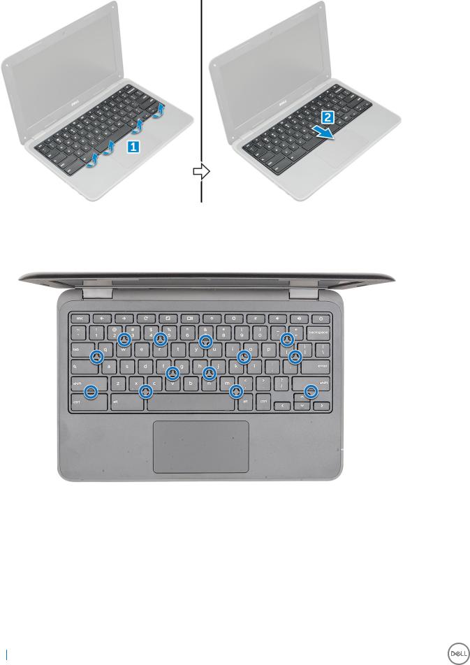
3 To remove keyboard:
aDisconnect the keyboard cable from the system board [1].
bUse the plastic scribe to the release the keyboard [2].

 NOTE: The two release holes for the keyboard are indicated by the "KB" labeling.
4 Slide and lift the keyboard away from the computer.
Removing and installing components |
11 |
|
|
Installing keyboard
1 Align the keyboard trim with the tabs on the computer, and press it until it clicks into place.
2Connect the keyboard cable on the system board.
3Install the:
abattery
bbase cover
cmicroSD card
4 Follow the procedure in After working inside your computer.
12 Removing and installing components
Audio board
Removing audio board
1Follow the procedure in Before working inside your computer.
2Remove the:
amicroSD card
bbase cover
cbattery
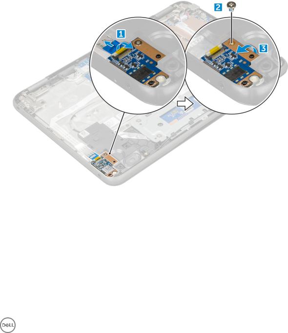
3 To remove the audio board:
aDisconnect the audio cable from the connector on the audio board [1].
bRemove the M.2.0x3.0 screw that secures the audio board on the computer [2].
cLift the audio board away from the computer [3].
Installing audio board
1Insert the audio board into the slot on the computer.
2Replace the M2.0x3.0 screw that secure the audio board to the computer.
3Connect the audio cable to the connector on the audio board.
4Install the:
abattery
bbase cover
cmicroSD card
5 Follow the procedure in After working inside your computer.
Removing and installing components |
13 |
|
|

Power connector port
Removing power connector port
1Follow the procedure in Before working inside your computer.
2Remove the:
amicroSD card
bbase cover
cbattery
3 To remove the power connector port:
aDisconnect the power connector cable from the connector on the system board [1].
bRemove the M.2.0x3.0 screws that secure the power connector port on the computer [2].
cSlide and lift the power connector port away from the computer [3].
Installing power connector port
1Insert the power connector port into the slot on the computer.
2Replace the M2.0x3.0 screw that secures the power connector port to the computer.
3Connect the power connector cable to the connector on the system board.
4Install the:
abattery
bbase cover
cmicroSD card
5 Follow the procedure in After working inside your computer.
14 Removing and installing components

Speaker
Removing speaker
1Follow the procedure in Before working inside your computer.
2Remove the:
amicroSD card
bbase cover
cbattery
3 To remove the speaker:
aDisconnect the speaker cable from the connector on the system board [1].
bRemove the adhesive tape that secures the speaker cable on the computer .
cUnroute the speaker cable from the routing channel [2].
4 Remove the speaker from the computer.
Removing and installing components |
15 |
|
|

Installing speakers
1Place the speakers into the slots on the computer.
2Route the speaker cable through the retention clips through routing channel.
3Affix the adhesive tape to secure the speaker cable on the computer.
4Connect the speaker cable to the connector on the system board.
5Install the:
abattery
bbase cover
cmicroSD card
6 Follow the procedure in After working inside your computer.
Touchpad panel
Removing touchpad
1Follow the procedure in Before working inside your computer.
2Remove the:
amicroSD card
bbase cover
cbattery
dspeaker
3 To remove touchpad cable:
aLift the latch, and disconnect the touchpad cable from the computer [1].
bRemove the touchpad cable [2].
16 Removing and installing components

4 To remove metal bracket:
aRemove the screws (M2.0x3.0, M.2.0x2.0) that secure the metal to the touchpad on the computer [1].
bRemove the adhesive tape [2].
cSlide and remove the metal bracket [3].

 NOTE: Remove the adhesive tape that secures the speaker cable on the metal bracket.
5 Remove the touchpad from the computer.
Removing and installing components |
17 |
|
|

Installing touchpad
1Place the touchpad into the slots on the computer.
2Place the metal bracket, and affix the adhesive tape.
3Replace the screws (M2.0x3.0, M.2.0x2.0) that secure the metal bracket on the computer.

 NOTE: Affix the adhesive tape that secures the speaker cable on the metal bracket.
4Connect the touchpad cable.
5Affix the adhesive tape to secure the speaker cable on the computer.
6Connect the speaker cable to the connector on the system board.
7Install the:
aspeaker
bbattery
cbase cover
dmicroSD card
8 Follow the procedure in After working inside your computer.
System board
Removing system board
1Follow the procedure in Before working inside your computer.
2Remove the:
amicroSD card
bbase cover
cbattery
18 Removing and installing components

3 Disconnect the following cables:
aaudio cable [1]
bkeyboard cable [2]
ctouch pad cable [3]
4 To disconnect the cable:
aDisconnect coin cell battery, power connector port, and speaker cable [1, 2, 3].
bRemove the M2.0xM3.0 screws and lift the metal bracket that secure on the system board [4, 5].
Removing and installing components |
19 |
|
|
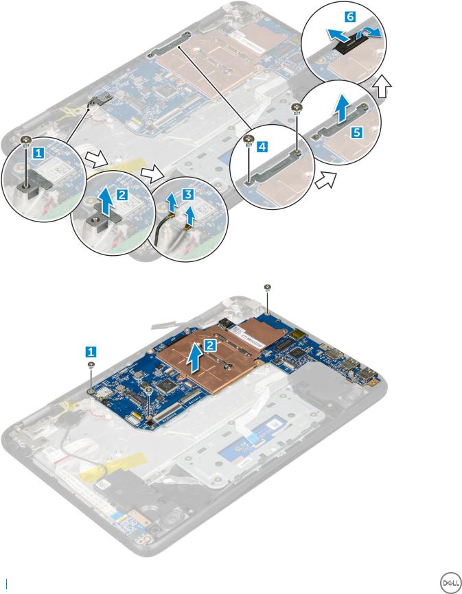
5 To remove metal bracket:
aRemove the screw M2.0x3.0 and lift the metal bracket that secures the WLAN card on the system board [1, 2]
bDisconnect the WLAN cables [3].
cRemove the screws M2.0x.30 and lift the metal bracket that secures the display cable on the computer [4, 5]
dLift the latch, and disconnect the cable [6]
6 Remove the M2. x3.0 screws and lift system board away from the computer[1 ,2]
20 Removing and installing components
Installing system board
1Align the system board with the screw holders on the computer.
2Tighten the M2.0x3.0 screws to secure the system board to the computer.
3Connect the display cable to the connector.
4Place the metal bracket over the connector and tighten the M2.0x3.0 screws to secure the display cable to the computer.
5Connect the WLAN cables.
6Place the metal bracket, and tighten the M2.0x3.0 screw to the WLAN cable on the system board.
7Place the metal and tighten M2.0x3.0 screws to secure on the system board.
8Connect the following cables:
apower connector cable
btouchpad cable
ckeyboard cable
dspeaker cable
epower board and audio cable
fsensor cable
9 Install the:
abattery
bbase cover
cmicroSD card
10 Follow the procedure in After working inside your computer.
Display assembly
Removing display assembly
1Follow the procedure in Before working inside your computer.
2Remove the:
amicroSD card
bbase cover
cbattery
3 To remove display cable:
aRemove the screws M2.0x.30 and lift the metal bracket that secures the display cable on the computer [1, 2].
bLift the latch, and disconnect the cable [3].
Removing and installing components |
21 |
|
|
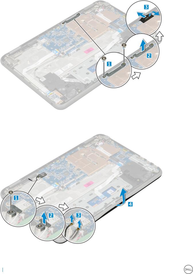
4 To disconnect WLAN cable:
aRemove the screw M2.0x3.0 and lift the metal bracket that secures the WLAN card on the system board [1, 2].
bDisconnect the WLAN cables [3].
cTurn over the computer [4].
5 To remove the display assembly:
aRemove the display hinge screws M2.0xM5.0 that secure the display assembly to the computer [1].
bLift the display assembly away from the computer [2].
22 Removing and installing components

Installing display assembly
1Place the display assembly to align with the screw holders on the computer.
2Replace the screws that secure the display hinges to the palm-rest assembly.
3Flip over the computer.
4Connect the display cable to the connector on the system board.
5Place the metal bracket over the (display cable) connector, and tighten the M2.0x3.0 screws to secure the display cable to the computer.
6Connect the WLAN cables.
7Place the metal bracket, and tighten the M2.0x3.0 screw to the WLAN cable on the system board.
8Install the:
abattery
bbase cover
cmicroSD card
9 Follow the procedure in After working inside your computer.
Removing and installing components |
23 |
|
|

Display bezel
Removing display bezel
1Follow the procedure in Before working inside your computer.
2Remove the:
amicroSD card
bbase cover
cbattery
3 Remove the hinge cap and the mylar cap that secures the display bezel to the display assembly [1,2].
4 Remove the M2.5x3.5 screws and pry the edges to release the display bezel from the display assembly
Installing display bezel
1Place the display bezel on the display assembly.
2Starting from the top corner, press on the display bezel and work around the entire bezel until it clicks on to the display assembly.
3Replace the M2.0x3.5 screws to secure the display bezel to the display assembly.
4Affix the hinge cap.
5Install the:
abattery
bbase cover
cmicroSD card
6 Follow the procedure in After working inside your computer
24 Removing and installing components
Loading...