


 Loading...
Dell Precision™ Workstation 490
Quick Reference Guide
Model DCTA
w w w . d e l l . c o m | s u p p o r t . d e l l . c o m

Notes, Notices, and Cautions
NOTE: A NOTE indicates important information that helps you make better use of your computer.
NOTICE: A NOTICE indicates either potential damage to hardware or loss of data and tells you how to avoid the problem.
 CAUTION: A CAUTION indicates a potential for property damage, personal injury, or death.
Abbreviations and Acronyms
For a complete list of abbreviations and acronyms, see the Glossary in your User’s Guide.
If you purchased a Dell™ n Series computer, any references in this document to Microsoft® Windows® operating systems are not applicable.
____________________
Information in this document is subject to change without notice. © 2006 Dell Inc. All rights reserved.
Reproduction in any manner whatsoever without the written permission of Dell Inc. is strictly forbidden.
Trademarks used in this text: Dell, the DELL logo and Dell Precision are trademarks of Dell Inc.; Intel, Xeon, and Pentium are registered trademarks of Intel Corporation; Microsoft and Windows are registered trademarks of Microsoft Corporation.
Other trademarks and trade names may be used in this document to refer to either the entities claiming the marks and names or their products. Dell Inc. disclaims any proprietary interest in trademarks and trade names other than its own.
Model DCTA
January 2006 |
P/N MD504 |
Rev. A00 |

Contents
Finding Information . . . . . . . . . . . . . . . . . . . . . . . . . . . . . . . . |
5 |
Setting Up Your Computer (Tower Orientation) . . . . . . . . . . . . . . . . . . |
9 |
Setting Up Your Computer (Desktop Orientation) . . . . . . . . . . . . . . . . |
14 |
About Your Computer. . . . . . . . . . . . . . . . . . . . . . . . . . . . . . . |
19 |
Front View (Tower Orientation) . . . . . . . . . . . . . . . . . . . . . . . |
19 |
Back View (Tower Orientation) . . . . . . . . . . . . . . . . . . . . . . . |
21 |
Back Panel Connectors. . . . . . . . . . . . . . . . . . . . . . . . . . . |
22 |
Front View (Desktop Orientation) . . . . . . . . . . . . . . . . . . . . . . |
24 |
Back View (Desktop Orientation) . . . . . . . . . . . . . . . . . . . . . . |
25 |
Inside View . . . . . . . . . . . . . . . . . . . . . . . . . . . . . . . . . |
26 |
Inside View – Hard Drive Bay Rotated Out . . . . . . . . . . . . . . . . . |
27 |
System Board Components . . . . . . . . . . . . . . . . . . . . . . . . . |
28 |
Cable Colors. . . . . . . . . . . . . . . . . . . . . . . . . . . . . . . . . |
29 |
Locating Your User’s Guide . . . . . . . . . . . . . . . . . . . . . . . . . . . |
29 |
Removing the Computer Cover. . . . . . . . . . . . . . . . . . . . . . . . . . |
30 |
Caring for Your Computer . . . . . . . . . . . . . . . . . . . . . . . . . . . . |
32 |
Solving Problems . . . . . . . . . . . . . . . . . . . . . . . . . . . . . . . . |
32 |
Troubleshooting Tips . . . . . . . . . . . . . . . . . . . . . . . . . . . . |
32 |
Resolving Software and Hardware Incompatibilities . . . . . . . . . . . |
32 |
Using Microsoft® Windows® XP System Restore . . . . . . . . . . . . . |
33 |
Using the Last Known Good Configuration . . . . . . . . . . . . . . . . . |
34 |
Dell Diagnostics. . . . . . . . . . . . . . . . . . . . . . . . . . . . . . . |
35 |
Before You Start Testing . . . . . . . . . . . . . . . . . . . . . . . . . . |
36 |
Beep Codes. . . . . . . . . . . . . . . . . . . . . . . . . . . . . . . . . . . . |
36 |
Error Messages . . . . . . . . . . . . . . . . . . . . . . . . . . . . . . . |
38 |
Diagnostic Lights. . . . . . . . . . . . . . . . . . . . . . . . . . . . . . . . . |
38 |
Diagnostic Light Codes Before POST. . . . . . . . . . . . . . . . . . . . |
38 |
Diagnostic Light Codes During POST . . . . . . . . . . . . . . . . . . . . |
40 |
Frequently Asked Questions . . . . . . . . . . . . . . . . . . . . . . . . . . . |
43 |
Index . . . . . . . . . . . . . . . . . . . . . . . . . . . . . . . . . . . . . . . . . |
45 |
Contents 3

4 Contents
Finding Information
NOTE: Some features or media may be optional and may not ship with your computer. Some features or media may not be available in certain countries.
NOTE: Additional information may ship with your computer.
What Are You Looking For? |
Find It Here |
|
|
|
|
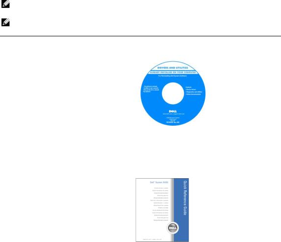
• A diagnostic program for my computer |
Drivers and Utilities CD (also known as Resource CD) |
|
• Drivers for my computer |
Documentation and |
|
• My computer documentation |
drivers are already |
|
• My device documentation |
installed on your |
|
• Desktop System Software (DSS) |
computer. You can use |
|
the CD to reinstall drivers, |
||
|
||
|
run the Dell Diagnostics, |
|
|
or access your |
|
|
documentation. Readme |
|
|
files may be included on |
|
|
your CD to provide last- |
|
|
minute updates about |
|
|
technical changes to your computer or advanced technical- |
|
|
reference material for technicians or experienced users. |
|
|
NOTE: Drivers and documentation updates can be found |
|
|
at support.dell.com. |
|
• How to set up my computer |
Quick Reference Guide |
|
• How to care for my computer |
|
|
• Basic troubleshooting information |
|
|
• How to run the Dell Diagnostics |
|
|
• Error codes and diagnostic lights |
|
|
• How to remove and install parts |
|
|
• How to open my computer cover |
|
|
|
NOTE: This document is available as a PDF at |
|
|
support.dell.com. |
Quick Reference Guide |
|
5 |
|
What Are You Looking For? |
Find It Here |
|
|
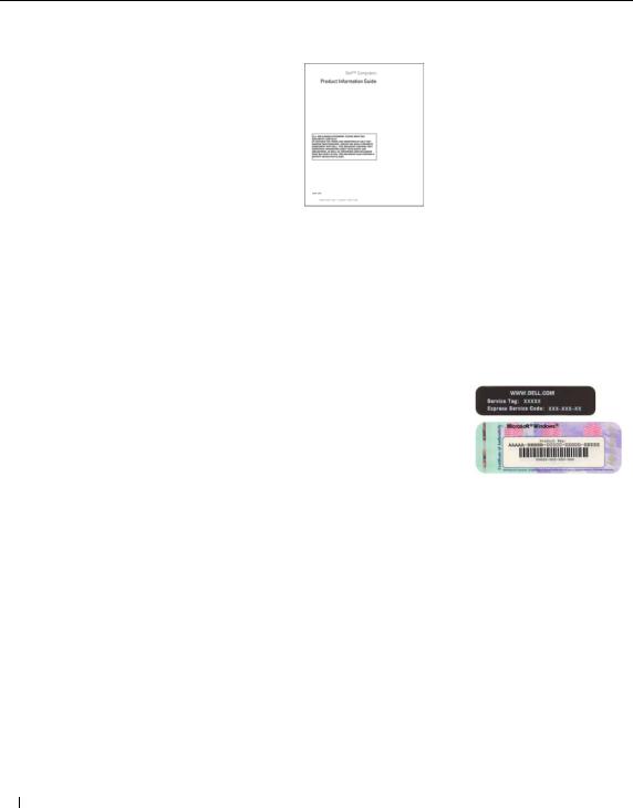
• Warranty information |
Dell™ Product Information Guide |
•Terms and Conditions (U.S. only)
•Safety instructions
•Regulatory information
•Ergonomics information
•End User License Agreement
•How to remove and replace parts
•Specifications
•How to configure system settings
•How to troubleshoot and solve problems
•Service Tag and Express Service Code
•Microsoft Windows License Label
User’s Guide
Microsoft®Windows® XP Help and Support Center
1 Click the Start button and click Help and Support
2 Click User’s and system guides and click User’s Guide
The User’s Guide is also available on the Drivers and Utilities CD.
Service Tag and Microsoft® Windows® License
These labels are located on your computer.
•Use the Service Tag to identify your computer when you use support.dell.com or contact technical support.
•Enter the Express
Service Code to direct your call when contacting technical support.
6 Quick Reference Guide

What Are You Looking For? |
Find It Here |
|
|
• Solutions — Troubleshooting hints and tips, articles |
Dell Support Website — support.dell.com |
from technicians, and online courses, frequently |
NOTE: Select your region or business segment to view the |
asked questions |
appropriate support site. |
• Community — Online discussion with other |
NOTE: Corporate, government, and education customers |
Dell customers |
can also use the customized Dell Premier support website at |
• Upgrades — Upgrade information for components, |
premier.support.dell.com. The website may not be available |
such as memory, the hard drive, and the |
in all regions. |
operating system |
|
•Customer Care — Contact information, service call and order status, warranty, and repair information
•Service and support — Service call status and support history, service contract, online discussions with technical support
•Reference — Computer documentation, details on my computer configuration, product specifications, and white papers
•Downloads — Certified drivers, patches, and software updates
•Desktop System Software (DSS)— If you reinstall the operating system for your computer, you should reinstall the DSS utility prior to installing any of the drivers. DSS provides critical updates for your operating system and support for Dell™ 3.5-inch USB floppy drives, optical drives, and USB devices. DSS is necessary for correct operation of your Dell computer. The software automatically detects your computer and operating system and installs the updates appropriate for your configuration.
• How to use Windows XP |
Windows Help and Support Center |
|
• How to work with programs and files |
1 |
Click the Start button and click Help and Support. |
• Documentation for devices (such as modem) |
2 |
Type a word or phrase that describes your problem |
|
|
and click the arrow icon. |
|
3 |
Click the topic that describes your problem. |
|
4 |
Follow the instructions on the screen. |
Quick Reference Guide |
|
7 |
|

What Are You Looking For? |
Find It Here |
|
|
• How to reinstall my operating system |
Operating System CD |
•How to use Linux
•E-mail discussions with users of Dell Precision™ products and the Linux operating system
•Additional information regarding Linux and my Dell Precision computer
The operating system is already installed on your computer. To reinstall your operating system, use the Operating System CD. See your User’s Guide for instructions. After you reinstall your operating system, use the Drivers and Utilities CD (Resource CD) to reinstall drivers for the
devices that came with your computer. Your operating system product key label is located on your computer.
NOTE: The color of your CD varies based on the operating system you ordered.
NOTE: The Operating System CD may be optional and may not ship with your computer.
Dell Supported Linux Sites
•Linux.dell.com
•Lists.us.dell.com/mailman/listinfo/linux-precision
8 Quick Reference Guide

Setting Up Your Computer (Tower Orientation)
CAUTION: Before you begin any of the procedures in this section, follow the safety instructions in the Product Information Guide.
You must complete all steps to properly set up your computer.
1 |
Connect the keyboard and the mouse. |
|
2 |
Connect the modem or the network cable. |
|
NOTICE: Do not connect a modem cable to the network adapter. Voltage from telephone communications can damage the network adapter.
NOTE: If your computer has a network card installed, connect the network cable to the card.
|
|
Quick Reference Guide |
|
9 |
|
|
|
||
|
|
|
||
|
|
|
||
|
|
|
||
|
|
|
||
|
|
|
||
|
|
|
||
|
3 |
Connect the monitor. |
|
Depending on your graphics card, you can connect your monitor in various ways.
NOTE: You may need to use the provided adapter or cable to connect your monitor to the computer.
10 Quick Reference Guide
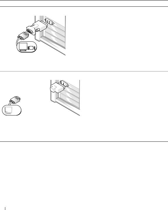
For singleand dual-monitor capable cards with a single connector
One VGA adapter:
 VGA
VGA
Use the VGA adapter when you have a single-monitor graphics card and you want to connect your computer to a VGA monitor.
Dual VGA Y cable adapter: |
Dual DVI Y cable adapter: |
VGA |
|
DVI |
|
|
|
|
VGA |
DVI |
|
|
Use the appropriate Y cable when your graphics card has a single connector and you want to connect your computer to one or two VGA monitors.
Use the appropriate Y cable when your graphics card has a single connector and you want to connect your computer to one or two DVI monitors.
The dual-monitor cable is color-coded; the blue connector is for the primary monitor, and the black connector is for the second monitor. To enable dual-monitor support, both monitors must be attached to the computer when you start the computer.
Quick Reference Guide |
|
11 |
|

For dual-monitor capable cards with one DVI connector and one VGA connector
One DVI connector and one VGA connector: |
Two VGA connectors with one VGA adapter: |
DVI
VGA |
VGA |
|
|
|
VGA |
Use the appropriate connector(s) when you want to connect your computer to one or two monitors.
Use the VGA adapter when you want to connect your computer to two VGA monitors.
For dual-monitor capable cards with two DVI connectors
Two DVI connectors: |
Two DVI connectors |
Two DVI connectors |
|
with one VGA adapter: |
with two VGA adapters: |
DVI
DVI
Use the DVI connectors to connect your computer
to one or two DVI monitors.
DVI
 VGA
VGA
Use the VGA adapter to connect a VGA monitor to one of the DVI connectors on your computer
 VGA
VGA
 VGA
VGA
Use two VGA adapters to connect two VGA monitors to the DVI connectors on your computer.
12 Quick Reference Guide

4 |
Connect the speakers. |
|
NOTE: If your computer has a sound card installed, connect the speakers to
the card.
Connect the power 5 cables and turn on the
computer and monitor.
|
|
|
|
|
|
|
|
|
|
|
|
|
|
|
|
|
|
13 |
|
|
|
|
|
|
|
|
|
|
|
|
|
|
|
|
|
|
|
|
|
|
|
|
|
|
|
|
|
|
|
|
|
|
|
|
|
|
|
|
|
|
|
|
|
|
|
|
|
|
|
|
|
|
|
|
|
|
|
|
|
|
|
|
|
|
|
|
|
|
|
|
|
|
|
|
|
|
|
|
|
|
|
|
|
|
|
|
|
|
|
|
|
|
|
|
|
|
|
|
|
|
|
|
|
|
|
|
Quick Reference Guide |
|
||||
|
|
|
|
|
|
|
|
|
|
|
|
|
|
|||||
|
|
|
|
|
|
|
|
|
|
|
|
|
|
|||||
|
|
|
|
|
|
|
|
|
|
|
|
|
|
|||||
|
|
|
|
|
|
|
|
|
|
|
|
|
|
|||||
|
|
|
|
|
|
|
|
|
|
|
|
|
|
|||||
|
|
|
|
|
|
|
|
|
|
|
|
|
|
|||||
|
|
|
|
|
|
|
|
|
|
|
|
|
|
|||||
|
|
|
|
|
|
|
|
|
|
|
|
|
|
|||||
|
|
|
|
|
|
|
|
|
|
|
|
|
|
|||||
|
|
|
|
|
|
|
|
|
|
|
|
|
|
|||||
|
|
|
|
|
|
|
|
|
|
|
|
|
|
|||||
|
||||||||||||||||||

6 |
Install additional software or devices. |
|
Before you install any devices or software that did not come with your computer, read the documentation that came with the software or device or contact the vendor to verify that the software or device is compatible with your computer and operating system.
You have now completed the setup for your tower computer.
Setting Up Your Computer (Desktop Orientation)
CAUTION: Before you begin any of the procedures in this section, follow the safety instructions in the Product Information Guide.
You must complete all steps to properly set up your computer.
1 |
Connect the keyboard |
and the mouse. |
NOTICE: Do not connect a modem cable to the network adapter. Voltage from telephone communications can damage the network adapter.
14 Quick Reference Guide
2 |
Connect the modem |
or the network cable. |
NOTE: If your computer has a network card installed, connect the network cable to the card.
3 |
Connect the monitor. |
|
Depending on your graphics card, you can connect your monitor in various ways.
NOTE: You may need to use the provided adapter or cable to connect your monitor to the computer.
|
|
|
|
|
|
|
|
|
|
|
|
|
|
|
|
|
|
15 |
|
|
|
|
|
|
|
|
|
|
|
|
|
|
|
|
|
|
|
|
|
|
|
|
|
|
|
|
|
|
|
|
|
|
|
|
|
|
|
|
|
|
|
|
|
|
|
|
|
|
|
|
|
|
|
|
|
|
|
|
|
|
|
|
|
|
|
|
|
|
|
|
|
|
|
|
|
|
|
|
|
|
|
|
|
|
|
|
|
|
|
|
|
|
|
|
|
|
|
|
|
|
|
|
|
|
|
|
|
|
|
|
|
|
|
|
|
|
|
|
|
|
|
|
|
|
|
|
|
|
|
|
|
|
|
|
|
|
|
|
|
|
|
|
|
|
|
|
|
|
|
|
|
|
|
|
|
|
|
|
|
|
|
|
|
|
|
|
|
|
|
|
|
|
|
|
|
|
|
|
|
|
|
|
|
|
|
|
|
|
|
|
|
|
|
|
|
|
|
|
|
|
|
|
|
|
|
|
|
|
|
|
|
|
|
|
|
|
|
|
|
|
|
|
|
|
|
|
|
|
|
|
|
|
|
|
|
|
|
|
Quick Reference Guide |
|
|||||
|
|
|
|
|
|
|
|
|
|
|
|
|
||||||
|
|
|
|
|
|
|
|
|
|
|
|
|
||||||
|
|
|
|
|||||||||||||||
For singleand dual-monitor capable cards with a single connector
VGA adapter:
 VGA
VGA
Use the VGA adapter when you have a single monitor graphics card and you want to connect your computer to a VGA monitor.
Dual VGA Y cable adapter: |
Dual DVI Y cable adapter: |
VGA |
DVI |
|
|
VGA |
DVI |
Use the appropriate Y cable when your graphics card has a single connector and you want to connect your computer to one or two VGA monitors.
Use the appropriate Y cable when your graphics card has a single connector and you want to connect your computer to one or two DVI monitors.
The dual-monitor cable is color-coded; the blue connector is for the primary monitor, and the black connector is for the second monitor. To enable dual-monitor support, both monitors must be attached to the computer when you start your computer.
16 Quick Reference Guide

For dual-monitor capable cards with one DVI connector and one VGA connector
One DVI connector and one VGA connector: |
Two VGA connectors with one VGA adapter: |
DVI
 VGA
VGA
Use the appropriate connector(s) when you want to connect your computer to one or two monitors.
 VGA
VGA
 VGA
VGA
Use the VGA adapter when you want to connect your computer to two VGA monitors.
For dual-monitor capable cards with two DVI connectors
Two DVI connectors: |
Two DVI connectors |
Two DVI connectors |
|
with one VGA adapter: |
with two VGA adapters: |
DVI |
DVI |
|
|
|
DVI |
|
VGA |
VGA |
VGA |
|
Use the DVI connector(s) to connect your computer to one or two DVI monitors.
Use the VGA adapter to connect a VGA monitor to one of the DVI connectors on your computer.
Use two VGA adapters to connect two VGA monitors to the DVI connectors on your computer.
Quick Reference Guide |
|
17 |
|
4 |
Connect the speakers. |
|
NOTE: If your computer has a sound card installed, connect the speakers to the card.
Connect the power cables 5 and turn on the computer
and monitor.
6 |
Install additional software or devices. |
|
Before you install any devices or software that did not come with your computer, read the documentation that came with the software or device or contact the vendor to verify that the software or device is compatible with your computer and operating system.
You have now completed the setup for your desktop computer.
18 Quick Reference Guide

About Your Computer
Front View (Tower Orientation)
|
1 |
|
2 |
13 |
3 |
|
|
12 |
4 |
|
|
11 |
|
|
5 |
10 |
6 |
|
9
8 
 7
7
1 |
upper 5.25-inch drive bay |
Holds a CD/DVD drive. |
|
|
|
2 |
lower 5.25-inch drive bay |
You can use this bay for an optional CD/DVD drive. |
|
|
|
3 |
FlexBay |
You can use this bay for an optional third hard drive (SATA or SAS), a floppy |
|
|
drive or Media Card Reader. |
|
|
|
4 |
hard-drive activity light |
The hard drive light is on when the computer reads data from or writes data to |
|
|
the hard drive. The light might also be on when a device such as your CD player |
|
|
is operating. |
|
|
|
5 |
IEEE 1394 connector |
Use the optional IEEE 1394 connector for high-speed data devices such as |
|
(optional) |
digital video cameras and external storage devices. |
|
|
|
Quick Reference Guide |
|
19 |
|

6 |
USB 2.0 connectors (2) |
Use the front USB connectors for devices that you connect occasionally, such as |
|
|
flash memory keys or cameras, or for bootable USB devices (see "System Setup" |
|
|
in your User’s Guide for more information on booting to a USB device). |
|
|
It is recommended that you use the back USB connectors for devices that |
|
|
typically remain connected, such as printers and keyboards. |
|
|
|
7 |
Dell™ rotatable badge |
To rotate the Dell badge for tower-to-desktop conversion; remove the front |
|
|
panel, turn it over, and rotate the plastic handle behind the badge. |
|
|
|
8 |
power button |
Press to turn on the computer. |
|
|
NOTICE: To avoid losing data, do not use the power button to turn off the computer. |
|
|
Instead, perform an operating system shutdown. |
|
|
NOTE: The power button can also be used to wake the system or to place it into |
|
|
a power-saving state. See "Power Management" in your User’s Guide for |
|
|
more information. |
|
|
|
9 |
power light |
The power light illuminates and blinks or remains solid to indicate different |
|
|
states: |
|
|
• No light — The computer is turned off. |
|
|
• Steady green — The computer is in a normal operating state. |
|
|
• Blinking green — The computer is in a power-saving state. |
|
|
• Blinking or solid amber — See "Power Problems" in your User’s Guide. |
|
|
To exit from a power-saving state, press the power button or use the keyboard or |
|
|
the mouse if it is configured as a wake device in the Windows Device Manager. |
|
|
For more information about sleep states and exiting from a power-saving state, |
|
|
see your User’s Guide. |
|
|
See "Diagnostic Lights" on page 38 for a description of light codes that can help |
|
|
you troubleshoot problems with your computer. |
|
|
|
10 |
headphone connector |
Use the headphone connector to attach headphones. |
|
|
|
11 |
microphone connector |
Use the microphone connector to attach a personal computer microphone for |
|
|
voice or musical input into a sound or telephony program. |
|
|
|
12 |
network link light |
The network link light is on when a good connection exists between a 10-Mbps, |
|
|
100-Mbps, or 1000-Mbps (or 1-Gbps) network and the computer. |
|
|
|
13 |
diagnostic lights (4) |
Use these lights to help you troubleshoot a computer problem based on the |
|
|
diagnostic code. For more information, see "Diagnostic Lights" on page 38. |
|
|
|
20 Quick Reference Guide
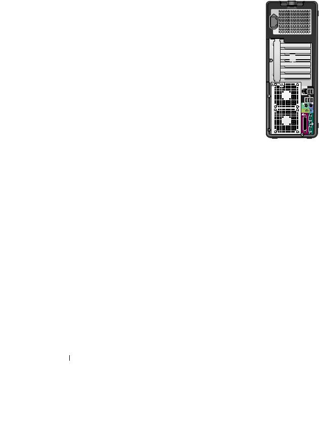
Back View (Tower Orientation)
 1
1
 2
2
3 |
|
|
|
|
|
|
|
|
|
|
1 |
power connector |
Insert the power cable. |
||
|
|
|
|
|
2 |
card slots |
Access connectors for any installed PCI, PCI-X, or PCI Express cards. |
||
NOTE: The center four slots support full-length cards: one PCI-X slot, one PCI Express x8 slot (wired as x4), one PCI Express x16 slot, and one PCI slot); and the top and bottom slots support half-length cards: one PCI-X slot and one PCI Express x8 slot (wired as x4).
3 |
back panel connectors Plug serial, USB, and other devices into the appropriate connectors. |
|
|
Quick Reference Guide |
|
21 |
|

Back Panel Connectors
1 |
2 |
3 |
|
|
4 |
5 |
6 |
|||
|
|
|
|
|
|
|
|
|
|
|
|
|
|
|
|
|
|
|
|
|
|
|
|
|
|
|
|
|
|
|
|
|
|
|
|
|
|
|
|
|
|
|
|
|
|
|
|
|
|
|
|
|
|
|
|
|
|
|
|
|
|
|
|
|
|
|
|
|
|
|
|
|
|
|
|
|
|
|
|
|
|
|
|
|
|
|
|
|
|
|
|
|
|
|
|
|
|
|
|
|
|
|
|
|
|
|
|
|
|
|
|
|
|
|
|
|
|
|
|
|
|
|
|
|
|
|
|
|
|
|
|
|
|
|
|
|
|
|
|
|
|
|
|
|
|
|
|
|
|
|
|
|
|
|
11 |
10 |
9 |
8 |
7 |
|
|
|
|||
1 |
parallel connector |
Connect a parallel device, such as a printer, to the parallel connector. If you have |
|||
|
|
a USB printer, plug it into a USB connector. |
|
||
|
|
NOTE: The integrated parallel connector is automatically disabled if the computer |
|||
|
|
detects an installed card containing a parallel connector configured to the same |
|||
|
|
address. For more information, see your User’s Guide. |
|||
|
|
|
|||
2 |
line-out/ headphone |
Use the green line-out connector to attach headphones and most speakers with |
|||
|
connector |
integrated amplifiers. |
|
|
|
|
|
On computers with a sound card, use the connector on the card. |
|||
|
|
|
|||
3 |
PS/2 mouse connector |
Plug a standard mouse into the green mouse connector. Turn off the computer |
|||
|
|
and any attached devices before you connect a mouse to the computer. If you |
|||
|
|
have a USB mouse, plug it into a USB connector. |
|||
|
|
If your computer is running the Microsoft® Windows® XP operating system, |
|||
|
|
the necessary mouse drivers have been installed on your hard drive. |
|||
|
|
|
|||
4 |
link integrity light |
• Green — A good connection exists between a 10-Mbps network and |
|||
|
|
the computer. |
|
|
|
•Orange — A good connection exists between a 100-Mbps network and the computer.
•Yellow — A good connection exists between a 1000-Mbps (or 1-Gbps) network and the computer.
•Off — The computer is not detecting a physical connection to the network.
22 Quick Reference Guide

5 |
network adapter |
To attach your computer to a network or broadband device, connect one end |
|
connector |
of a network cable to either a network jack or your network or broadband device. |
|
|
Connect the other end of the network cable to the network adapter connector |
|
|
on your computer. A click indicates that the network cable has been |
|
|
securely attached. |
|
|
NOTE: Do not plug a telephone cable into the network connector. |
|
|
On computers with an additional network connector card, use the connectors |
|
|
on the card and on the back of the computer when setting up multiple network |
|
|
connections (such as a separate intraand extranet). |
|
|
It is recommended that you use Category 5 wiring and connectors for your |
|
|
network. If you must use Category 3 wiring, force the network speed to 10 Mbps |
|
|
to ensure reliable operation. |
|
|
|
6 |
network activity light |
Flashes a yellow light when the computer is transmitting or receiving network |
|
|
data. A high volume of network traffic may make this light appear to be in a |
|
|
steady "on" state. |
|
|
|
7 |
USB 2.0 connectors (5) |
It is recommended that you use the front USB connectors for devices that you |
|
|
connect occasionally, such as flash memory keys or cameras, or for bootable |
|
|
USB devices. |
|
|
Use the back USB connectors for devices that typically remain connected, |
|
|
such as printers and keyboards. |
|
|
|
8 |
PS/2 keyboard connector |
If you have a standard keyboard, plug it into the purple keyboard connector. |
|
|
If you have a USB keyboard, plug it into a USB connector. |
|
|
|
9 |
line-in connector |
Use the blue line-in connector to attach a record/playback device such |
|
|
as a cassette player, CD player, or VCR. |
|
|
On computers with a sound card, use the connector on the card. |
|
|
|
10 |
serial connector |
Connect a serial device, such as a handheld device, to the serial port. If necessary, |
|
|
the address for this port can be modified through system setup. See your |
|
|
User’s Guide for more information. |
|
|
|
11 |
serial connector |
Connect a serial device, such as a handheld device, to the serial port. If necessary, |
|
|
the address for this port can be modified through system setup. See your |
|
|
User’s Guide for more information. |
|
|
|
Quick Reference Guide |
|
23 |
|

Front View (Desktop Orientation)
1 |
2 |
3 |
|
|
4 |
5 |
6 |
7 |
|||||
|
|
|
|
|
|
|
|
|
|
|
|
|
|
|
|
|
|
|
|
|
|
|
|
|
|
|
|
|
|
|
|
|
|
|
|
|
|
|
|
|
|
|
|
|
|
|
|
|
|
|
|
|
|
|
|
|
|
|
|
|
|
|
|
|
|
|
|
|
|
|
|
|
|
|
|
|
|
|
|
|
|
|
|
|
|
|
|
|
|
|
|
|
|
|
|
|
|
|
|
|
|
|
|
|
|
|
|
|
|
|
|
|
|
|
|
|
|
|
|
|
|
|
|
|
|
|
|
|
|
|
|
|
|
|
|
|
|
|
|
|
|
|
|
|
|
|
|
|
|
|
|
|
|
|
|
|
|
|
|
|
|
|
|
|
|
|
|
|
13 |
12 |
11 |
10 |
9 |
8 |
|
|
|
|
|
|
|
1 |
upper 5.25-inch drive bay |
Holds a CD/DVD drive. |
|
|
|
|
|
|
|
||||
2 |
lower 5.25-inch drive bay |
You can use the bay for an optional CD/DVD drive, or a SATA hard drive. |
||||
|
|
|
||||
3 |
FlexBay |
You can use the bay for a floppy drive, or a Media Card Reader. |
||||
|
|
|
||||
4 |
IEEE 1394 connector |
Use the optional IEEE 1394 connector for high-speed data devices such as digital |
||||
|
(optional) |
video cameras and external storage devices. |
||||
|
|
|
||||
5 |
USB 2.0 connectors (2) |
Use the front USB connectors for devices that you connect occasionally, such as |
||||
|
|
flash memory keys or cameras, or for bootable USB devices (see "System Setup" |
||||
|
|
in your User’s Guide for more information on booting to a USB device). |
||||
|
|
It is recommended that you use the back USB connectors for devices that |
||||
|
|
typically remain connected, such as printers and keyboards. |
||||
|
|
|
||||
6 |
hard-drive activity light |
The hard drive light is on when the computer reads data from or writes data to |
||||
|
|
the hard drive. The light might also be on when a device such as your CD player |
||||
|
|
is operating. |
|
|
|
|
|
|
|
||||
7 |
Dell™ rotatable badge |
To rotate the Dell badge for tower-to-desktop conversion; remove the front panel, |
||||
|
|
turn it over, and rotate the plastic handle behind the badge. |
||||
|
|
|
|
|
||
8 |
power button |
Press to turn on the computer. |
|
|
||
|
|
NOTICE: To avoid losing data, do not use the power button to turn off the computer. |
||||
|
|
Instead, perform an operating system shutdown. |
||||
NOTE: The power button can also be used to wake the system or to place it into a power-saving state. See your User’s Guide for more information.
24 Quick Reference Guide

9 |
power light |
The power light illuminates and blinks or remains solid to indicate |
|
|
different states: |
|
|
• No light — The computer is turned off. |
|
|
• Steady green — The computer is in a normal operating state. |
|
|
• Blinking green — The computer is in a power-saving state. |
|
|
• Blinking or solid amber — See "Power Problems" in your User’s Guide. |
|
|
To exit from a power-saving state, press the power button or use the keyboard or |
|
|
the mouse if it is configured as a wake device in the Windows Device Manager. |
|
|
For more information about sleep states and exiting from a power-saving state, |
|
|
see your User’s Guide. |
|
|
See "Diagnostic Lights" on page 38 for a description of light codes that can help |
|
|
you troubleshoot problems with your computer. |
|
|
|
10 |
headphone connector |
Use the headphone connector to attach headphones. |
|
|
|
11 |
microphone connector |
Use the microphone connector to attach a personal computer microphone for |
|
|
voice or musical input into a sound or telephony program. |
|
|
|
12 |
network link light |
The network link light is on when a good connection exists between a 10-Mbps, |
|
|
100-Mbps, or 1000-Mbps (or 1-Gbps) network and the computer. |
|
|
|
13 |
diagnostic lights (4) |
Use these lights to help you troubleshoot a computer problem based on the |
|
|
diagnostic code. For more information, see "Diagnostic Lights" on page 38. |
|
|
|
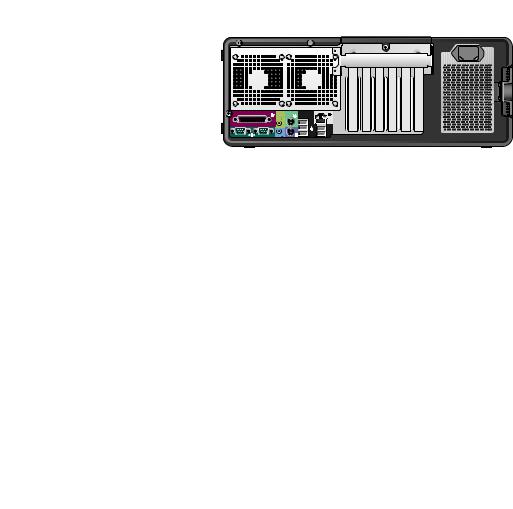
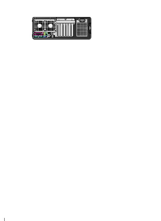
Back View (Desktop Orientation)
1 2 3
|
|
|
|
|
|
|
|
|
|
|
|
|
|
|
|
|
|
|
|
|
|
|
|
|
|
|
|
|
|
|
|
|
|
|
|
|
|
|
|
|
|
|
|
|
|
|
|
|
|
|
|
|
|
|
|
|
|
|
|
|
|
|
|
|
|
|
|
|
|
|
|
|
|
|
|
|
|
|
|
|
|
|
|
|
|
|
|
|
|
|
|
|
|
|
|
|
|
|
|
|
|
|
|
|
|
|
|
|
|
|
|
|
|
|
|
|
|
|
|
|
|
|
|
|
|
|
|
|
|
|
|
|
|
|
|
|
|
|
|
|
|
|
|
|
|
|
|
|
|
|
|
|
|
|
|
|
|
|
|
|
|
|
|
|
|
|
|
|
|
|
|
|
|
|
|
|
|
|
|
|
|
|
|
|
|
|
|
|
|
|
|
|
|
|
|
|
|
|
|
|
|
|
|
|
|
|
|
|
|
|
|
|
|
|
|
|
|
|
|
|
1 |
back panel connectors |
Plug serial, USB, and other devices into the appropriate connector. |
||||||||||||||
|
|
|
|
|
|
|
|
|
|
|
|
|
|
|
|
|
2 |
card slots |
Access connectors for any installed PCI, PCI-X, or PCI Express cards. |
||||||||||||||
|
|
|
NOTE: The slot farthest to the left and the two slots on the right support half-length |
|||||||||||||
|
|
|
cards: one PCI Express x8 slot (wired as x4) and two PCI-X slots. The center three slots |
|||||||||||||
|
|
|
support full-length cards: one PCI Express x16 slot, one PCI Express x8 slot (wired as x4) |
|||||||||||||
|
|
|
and one PCI slot. |
|||||||||||||
|
|
|
|
|
|
|
|
|
|
|
|
|
|
|
|
|
3 |
power connector |
Insert the power cable. |
||||||||||||||
|
|
|
|
|
|
|
|
|
|
|
|
|
|
|
|
|
Quick Reference Guide |
|
25 |
|

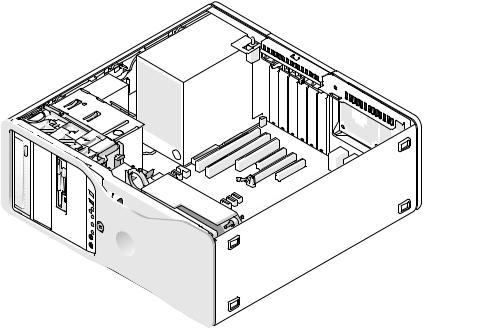
Inside View
1
5
4
3 |
2 |
1 |
power supply |
2 |
rotatable hard drive bay |
3 |
FlexBay |
4 |
lower 5.25-inch drive bay |
5 |
upper 5.25-inch drive bay |
|
|
26 Quick Reference Guide
Inside View – Hard Drive Bay Rotated Out
1
2
3
5
|
|
|
|
4 |
|
1 |
power supply |
2 |
system board |
3 |
memory fan |
4 |
front fan |
5 |
card fan |
|
|
Quick Reference Guide |
|
27 |
|

System Board Components
1 |
2 |
3 |
4 |
5 |
6 |
7 |
8 |
9 |
10 |
11 |
12 |
|
|
|
|
|
|
|
|
|
|
|
13 |
|
|
|
|
|
|
|
|
|
|
|
14 |
|
|
|
|
|
|
|
|
|
|
|
15 |
27 |
|
|
|
|
|
|
|
|
|
|
|
|
|
|
|
|
|
|
|
|
|
|
16 |
|
|
|
|
|
|
|
|
|
|
|
17 |
26 |
|
|
|
|
|
|
|
|
|
|
|
|
|
|
|
|
|
|
|
|
|
|
18 |
|
|
|
|
|
|
|
|
|
|
|
19 |
|
|
|
|
|
|
|
|
|
|
|
20 |
|
|
|
|
|
|
|
|
|
|
|
21 |
|
|
|
|
|
25 |
24 |
|
|
23 |
|
22 |
28 Quick Reference Guide

1primary processor connector (CPU_0)
2secondary processor connector (CPU_1)
3front fan connector (FAN_FRONT)
4card cage fan (FAN_CCAG)
5internal speaker connector (INT_SPKR)
6power connector (POWER2)
7IDE drive connector (IDE)
8standby power light (AUX_PWR)
9password jumper (PSWD)
10auxiliary hard-drive LED connector (AUX_LED)
11RTC reset jumper (RTCRST)
12battery socket (BATTERY))
13main power connector (POWER1)
14SATA connectors (SATA_4, SATA_3)
15Flexbay connector (USB)
16SATA connectors (SATA_2, SATA_1, SATA_0)
17floppy drive (DSKT)
18front panel connector (FRONTPANEL)
19PCI-X card slot (SLOT6_PCIX)
20PCI-X card slot (SLOT5_PCIX)
21chassis intrusion header (INTRUDER)
22PCI card slot (SLOT4_PCI)
23PCI-Express x8 card slot, wired as x4 (SLOT3_PCIE)
24PCI-Express x16 card slot (SLOT2_PCIE)
25PCI-Express x8 card slot, wired as x4 (SLOT1_PCIE)
26memory module connectors (DIMM_1-8)
27memory fan connector (FAN_MEM)
Cable Colors
Device |
Color |
|
|
SATA Hard drive |
blue cable |
|
|
Floppy drive |
black pull-tab |
|
|
CD/DVD drive |
orange pull-tab |
|
|
front panel |
yellow pull-tab |
|
|
Locating Your User’s Guide
Your User’s Guide contains additional information about your computer such as:
•Technical specifications
•Information for changing the orientation of your computer from a desktop to a tower
•Front and back views of your computer, including all of the available connectors
•Inside views of your computer, including a detailed graphic of the system board and the connectors
•Instructions for cleaning your computer
•Information on software features, such as Legacy Select Technology control, using a password, and system setup options
Quick Reference Guide |
|
29 |
|

•Tips and information for using the Microsoft Windows XP operating system
•Instructions for removing and installing parts, including memory, cards, drives, the microprocessor, and the battery
•Information for troubleshooting various computer problems
•Instructions for using the Dell Diagnostics and reinstalling drivers
•Information on how to contact Dell
You can access the User’s Guide from your hard drive or the Dell Support website at support.dell.com.
Removing the Computer Cover
CAUTION: Before you begin any of the procedures in this section, follow the safety instructions in the
Product Information Guide.
CAUTION: To guard against electrical shock, always unplug your computer from the electrical outlet before removing the cover.
NOTICE: To prevent static damage to components inside your computer, discharge static electricity from your body before you touch any of your computer’s electronic components. You can do so by touching an unpainted metal surface on the computer.
1 Follow the procedures in "Before You Begin" in your User’s Guide.
NOTICE: Opening the computer cover while the computer is running could result in a shutdown without warning and a loss of data in open programs. The computer cooling system cannot function properly while the cover
is removed.
2 If you have installed a security cable, remove it from the security cable slot.
NOTICE: Ensure that sufficient space exists to support the removed cover—at least 30 cm (1 ft) of desk top space.
NOTICE: Ensure that you are working on a level, protected surface to avoid scratching either the computer or the surface on which it is resting.
3 Lay your computer on a flat surface with the cover facing up.
30 Quick Reference Guide
Loading...