


 Loading...
Dell™ PowerVault™
MD3000i RAID Enclosure
Hardware Owner’s Manual

Notes, Notices, and Cautions
NOTE: A NOTE indicates important information that helps you make better use of your computer.
NOTICE: A NOTICE indicates either potential damage to hardware or loss of data and tells you how to avoid the problem.
CAUTION: A CAUTION indicates a potential for property damage, personal injury, or death.
____________________
Information in this document is subject to change without notice. © 2007 Dell Inc. All rights reserved.
Reproduction in any manner whatsoever without the written permission of Dell Inc. is strictly forbidden.
Trademarks used in this text: Dell, the DELL logo, PowerEdge, and PowerVault are trademarks of Dell Inc.; Microsoft, Windows, Windows Server, and MS-DOS are either trademarks or registered trademarks of Microsoft Corporation in the United States and/or other countries; UNIX is a registered trademark of The Open Group in the United States and other countries.
Other trademarks and trade names may be used in this document to refer to either the entities claiming the marks and names or their products. Dell Inc. disclaims any proprietary interest in trademarks and trade names other than its own.
Model AMP01
June 2007 |
Rev. A00 |

Contents
1 About Your System . . . . . . . . . . . . . . . . . . |
9 |
Overview . . . . . . . . . . . . . . . . . . . . . . . . . |
9 |
Enclosure Features . . . . . . . . . . . . . . . . . . |
9 |
Modular Disk Storage Manager . . . . . . . . . . |
11 |
Other Information You May Need . . . . . . . . . . . . |
11 |
Connection Components . . . . . . . . . . . . . . . . |
12 |
About the Enclosure Connections . . . . . . . . . . . |
12 |
Hardware Features . . . . . . . . . . . . . . . . . . . |
13 |
Indicators on the Enclosure Bezel . . . . . . . . . |
13 |
Front-Panel Indicators and Features . . . . . . . |
14 |
Back-Panel Indicators and Features . . . . . . . |
18 |
RAID Controller Modules . . . . . . . . . . . . . |
18 |
Cache Functions and Features . . . . . . . . . . . |
24 |
Power Supply and Cooling Fan Features . . . . . |
24 |
2 Using Your RAID Enclosure . . . . . . . . . . . |
27 |
Physical Disks, Virtual Disks, and Disk Groups . . . . |
27 |
Physical Disks . . . . . . . . . . . . . . . . . . . |
28 |
Physical Disk States . . . . . . . . . . . . . . . . |
28 |
Self-Monitoring Analysis and Reporting |
|
Technology (SMART) . . . . . . . . . . . . . . . . |
29 |
Virtual Disks and Disk Groups . . . . . . . . . . . |
30 |
Contents 3

Supported RAID Levels . . . . . . . . . . . . . . . . . |
31 |
RAID 0 . . . . . . . . . . . . . . . . . . . . . . . |
31 |
RAID 1 . . . . . . . . . . . . . . . . . . . . . . . |
31 |
RAID 5 . . . . . . . . . . . . . . . . . . . . . . . |
32 |
RAID 10 . . . . . . . . . . . . . . . . . . . . . . . |
32 |
RAID Level Usage . . . . . . . . . . . . . . . . . |
32 |
Segment Size . . . . . . . . . . . . . . . . . . . . |
33 |
Hot Spares and Rebuild . . . . . . . . . . . . . . . . . |
33 |
Global Hot Spares . . . . . . . . . . . . . . . . . |
33 |
Hot Spare Operation . . . . . . . . . . . . . . . . |
33 |
Rebuild . . . . . . . . . . . . . . . . . . . . . . . |
34 |
Media Errors and Unreadable Sectors . . . . . . . . . |
34 |
RAID Operations and Features . . . . . . . . . . . . . |
35 |
Virtual Disk Operations . . . . . . . . . . . . . . . |
35 |
Disk Group Operations . . . . . . . . . . . . . . . |
37 |
RAID Background Operations Priority . . . . . . . |
39 |
Virtual Disk Migration and Disk Roaming . . . . . |
40 |
Advanced Features . . . . . . . . . . . . . . . . . . . |
42 |
Storage Partitions . . . . . . . . . . . . . . . . . |
42 |
Host Types . . . . . . . . . . . . . . . . . . . . . |
44 |
Snapshot Virtual Disks . . . . . . . . . . . . . . . |
44 |
Snapshot Repository Virtual Disk . . . . . . . . . |
45 |
Virtual Disk Service . . . . . . . . . . . . . . . . . |
46 |
Volume Shadow-Copy Service . . . . . . . . . . . |
46 |
Virtual Disk Copy . . . . . . . . . . . . . . . . . . |
47 |
Using Snapshot and Disk Copy Together . . . . . . |
48 |
Hardware Redundancy and Failover . . . . . . . . . . |
48 |
Redundancy and Non-Redundancy . . . . . . . . |
49 |
Multi-Path Software . . . . . . . . . . . . . . . . |
49 |
4 Contents
When a RAID Controller Module Is Replaced
or Removed . . . . . . . . . . . . . . . . . . . . . |
50 |
RAID Controller Failover Modes . . . . . . . . . . |
51 |
Thermal Shutdown . . . . . . . . . . . . . . . . . . . |
52 |
Updating Enclosure Firmware . . . . . . . . . . . . . |
52 |
RAID Controller Module Firmware . . . . . . . . . |
52 |
Physical Disk Firmware . . . . . . . . . . . . . . |
53 |
Expansion Enclosure Firmware . . . . . . . . . . |
53 |
Best Practices and Recommendations . . . . . . . . . |
54 |
3 Installing Enclosure Components . . . . . . 55
Recommended Tools . . . . . . . . . . . . . . . . . . |
55 |
|
|
Removing and Replacing the Front Bezel . . . . . . . . |
55 |
|
|
Removing and Installing Physical Disks . . . . . . . . |
56 |
|
|
Removing Physical Disks from the Enclosure . . . |
57 |
|
|
Installing SAS Physical Disks in the |
|
|
|
Enclosure . . . . . . . . . . . . . . . . . . . . . . |
58 |
|
|
Removing and Installing a RAID Controller |
|
|
|
Module . . . . . . . . . . . . . . . . . . . . . . . . . . |
60 |
|
|
Removing a RAID Controller Module . . . . . . . |
60 |
|
|
Installing a RAID Controller Module . . . . . . . . |
61 |
|
|
Removing and Installing a RAID Controller |
|
|
|
Module Backup Battery Unit . . . . . . . . . . . . . . |
62 |
|
|
Removing and Installing the Power Supply/Cooling |
|
|
|
Fan Module . . . . . . . . . . . . . . . . . . . . . . . |
64 |
|
|
Removing a Power Supply/Cooling |
|
|
|
Fan Module . . . . . . . . . . . . . . . . . . . . . |
64 |
|
|
Installing a Power Supply/Cooling |
|
|
|
Fan Module . . . . . . . . . . . . . . . . . . . . . |
65 |
|
|
Contents |
|
|
5 |
|

Removing and Installing the Control Panel . . . . . . . |
66 |
Removing the Control Panel . . . . . . . . . . . . |
66 |
Installing the Control Panel . . . . . . . . . . . . |
67 |
Removing and Installing the Midplane . . . . . . . . . |
68 |
4 Troubleshooting Your Enclosure . . . . . . . 71
Safety First—For You and Your Enclosure . . . . . . . |
71 |
Start-Up Routine . . . . . . . . . . . . . . . . . . . . . |
71 |
Troubleshooting External Connections . . . . . . . . . |
72 |
Troubleshooting a Wet Enclosure . . . . . . . . . . . . |
72 |
Troubleshooting a Damaged Enclosure . . . . . . . . . |
73 |
Troubleshooting Power Supplies . . . . . . . . . . . . |
73 |
Troubleshooting Enclosure Cooling Problems . . . . . |
75 |
Troubleshooting a Fan . . . . . . . . . . . . . . . |
75 |
Troubleshooting SAS Physical Disks . . . . . . . . . . |
76 |
Troubleshooting Enclosure Connections . . . . . . . . |
77 |
Hard Controller Failures and Lockdown |
|
Conditions . . . . . . . . . . . . . . . . . . . . . . . . |
78 |
Invalid Enclosure . . . . . . . . . . . . . . . . . . |
78 |
ECC Errors . . . . . . . . . . . . . . . . . . . . . |
78 |
PCI Errors . . . . . . . . . . . . . . . . . . . . . . |
79 |
Critical Conditions . . . . . . . . . . . . . . . . . |
79 |
Noncritical Conditions . . . . . . . . . . . . . . . |
79 |
6 Contents

5 Getting Help . . . . . . . . . . . . . . . . . . . . . . |
81 |
Obtaining Assistance . . . . . . . . . . . . . . . . . . |
81 |
Technical Support and Customer Service . . . . . |
82 |
Online Services . . . . . . . . . . . . . . . . . . |
82 |
Automated Order-Status Service . . . . . . . . . |
83 |
Dell Enterprise Training . . . . . . . . . . . . . . . . . |
83 |
Problems With Your Order . . . . . . . . . . . . . . . |
83 |
Product Information . . . . . . . . . . . . . . . . . . . |
83 |
Returning Items for Warranty Repair or Credit . . . . . |
83 |
Before You Call . . . . . . . . . . . . . . . . . . . . . |
84 |
Contacting Dell . . . . . . . . . . . . . . . . . . . . . |
84 |
Glossary . . . . . . . . . . . . . . . . . . . . . . . . . . . . . 87
Contents 7

8 Contents

About Your System
The Dell™ PowerVault™ MD3000i is a 3U rack-mounted external Redundant Array of Independent Disks (RAID) storage array capable of accommodating up to 15 3.0-Gbps, Serial-Attached SCSI (SAS) disks. The RAID enclosure can be daisy-chained with up to two additional MD1000 expansion enclosures, providing access to a maximum of 45 disks in the entire storage array. Connectivity between the RAID enclosure and the host server is provided by a standard Ethernet connection, and communication between the two is established through an iSCSI initiator.
Overview
The RAID enclosure is designed for high availability, offering redundant access to data storage. It features support for both single RAID controller configuration and dual RAID controller configuration. For each configuration, up to 16 hosts can be connected through industry-standard 1-Gb network interface cards (NICs).
The MD3000i storage array provides dual active/active RAID controller modules, redundant power supplies, and redundant fans. The RAID enclosure is designed for high-performance environments: eight-node clusters or multi-host storage access for up to 16 host servers.
Storage management can be either in-band through the iSCSI connection, or out-of-band using an Ethernet connection to the Management Port on the RAID controller modules.
Enclosure Features
Features include:
•Support for up to 16 Microsoft Windows® or Linux host servers
•3U chassis for rack mounting
•RAID controller modules in two supported configurations:
–Single-controller configurations
–Dual-controller configurations for high availability
About Your System |
|
9 |
|

•Two redundant, hot-pluggable power supply/fan modules
•512 MB of mirrored cache on each RAID controller module
•Battery backup unit in each RAID controller module that protects against cache data loss for up to 72 hours
•Support for up to 45 3.5" SAS physical disks
•Support for up to 255 virtual disks per disk group
•Up to 2 TB (2036 GB) storage on a single virtual disk
•Support for up to two PowerVault MD1000 expansion enclosures through SAS Out port connectors on the RAID controller modules
•Online firmware updates (without taking the enclosure offline) for the following components:
–RAID controller modules
–NVSRAM
–Physical disk
NOTE: Dell recommends stopping all I/O to the array when downloading physical disk firmware.
– Expansion enclosure management modules (EMMs)
•Task-based configuration software (MD Storage Manager)
•Optional snapshot virtual disk (premium feature), up to four snapshots per virtual disk and 128 snapshots per array
•Optional virtual disk copy (premium feature), up to 255 virtual disk copies per array
•Continuous background event monitoring for critical problems, such as impending physical disk failure or failed RAID controller modules
•Host-based, multipath failover software for redundant configurations to automatically reroute I/O activity from a failed, offline, or removed RAID controller module to its alternate RAID controller module (or from a failed iSCSI connection). This capability maintains a data path between the host server and the storage array.
10 |
About Your System |
Modular Disk Storage Manager
The Modular Disk (MD) Storage Manager software is a graphic interface with wizard-guided tools and a task-based management structure designed to reduce the complexity of installation, configuration, management, and diagnostic tasks. MD Storage Manager can be used on any host server attached to the storage array, as well as on storage management stations connected to the same subnetwork as the RAID enclosure, to create and manage multiple storage arrays.
NOTE: The MD Storage Manager uses TCP/UDP port 2463 for discovery and management of the MD3000i storage array.
For more information, see the MD Storage Manager User's Guide.
Other Information You May Need
CAUTION: The Product Information Guide provides important safety and regulatory information. Warranty information may be included within this document or as a separate document.
•The Rack Installation Guide or Rack Installation Instructions included with your rack solution describes how to install your enclosure into a rack.
•Getting Started With Your System provides an overview of enclosure features, setting up your enclosure, and technical specifications.
•Setting Up Your PowerVault MD3000i provides an overview of setting up and cabling your storage array.
•The PowerVault MD3000i Installation Guide provides installation and configuration instructions for both software and hardware.
•The PowerVault MD Storage Manager CLI Guide provides information about using the command line interface (CLI).
•The Dell PowerVault MD3000i Resource CD provides documentation for configuration and management tools, as well as the full documentation set.
•Dell PowerVault MD1000 Documentation is available at support.dell.com for users who incorporate MD1000 expansion enclosures.
•Dell PowerEdge Cluster Documentation is available at support.dell.com. A link to clustering documentation is also included on the Resource CD under Product Documentation.
About Your System |
|
11 |
|

•Updates are sometimes included to describe changes to the enclosure, software, and/or documentation.
NOTE: Always check for updates on support.dell.com and read the updates first because they often supersede information in other documents.
•Release notes or readme files are included to provide last-minute updates to the enclosure or documentation or advanced technical reference material intended for experienced users or technicians.
Connection Components
Before connecting your RAID enclosure, ensure that the following are available:
•The components that shipped with your RAID enclosure, including:
–Power cords (2)
–MD3000i Resource CD
–Setting Up Your PowerVault MD3000i
–Rail kit
•Any relevant documentation, including:
–Getting Started With Your System
–Rack Installation Guide or Rack Installation Instructions
–Product Information Guide (for important safety, regulatory, and warranty information)
–Readme files
•#2 Phillips screwdriver
About the Enclosure Connections
The RAID enclosure is connected to a host server via two RAID controller modules. The RAID controller modules are identified as RAID controller module 0 and RAID controller module 1 (see Figure 1-4).
Each RAID controller module has two iSCSI In port connectors that provide connection to the host server. The iSCSI In port connectors are labeled 0 and 1.
12 |
About Your System |
Each MD3000i RAID controller module also contains a SAS Out port connector. This port allows you the option to connect the RAID enclosure to an expansion enclosure.
Refer to the PowerVault MD3000i Installation Guide for details and illustrated examples of how to configure your storage array.
Hardware Features
The remainder of this section describes the hardware features available on the RAID enclosure, including:
•Indicators on the enclosure bezel
•Front-panel and back-panel indicators and features
•Redundant power supply and cooling fan modules
Indicators on the Enclosure Bezel
An optional locking bezel can be installed on the front of the enclosure to limit access. Figure 1-1 illustrates the indicators and components on the bezel. Table 1-1 lists conditions indicated by the lights on the bezel. For information on installing and removing the bezel, see "Removing and Replacing the Front Bezel" on page 55.
Figure 1-1. LEDs on the Front Bezel
1 
2 


3 
About Your System |
|
13 |
|
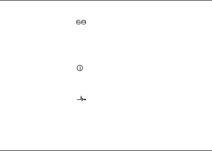
Table 1-1. Front-Bezel Indicators
Item |
LED Indicator |
LED Icon Condition |
|
|
|
|
|
1 |
Split mode (green) |
|
Because this mode is unused in the system, |
|
|
|
this LED should always be unlit. |
|
|
|
NOTE: This LED comes on if the enclosure |
|
|
|
mode switch on the enclosure’s front panel is |
|
|
|
in the split mode position before the |
|
|
|
enclosure is turned on. |
|
|
|
|
2 |
Power (green) |
|
When lit, at least one power supply is |
|
|
|
supplying power to the enclosure. |
|
|
|
|
3 |
Enclosure status |
|
Steady amber: Power is on and enclosure is |
|
(blue/amber) |
|
in reset state. |
Steady blue: Power is on and enclosure status is OK.
Flashing blue: Enclosure LED is being blinked by MD Storage Manager.
Flashing amber: Enclosure is in fault state.
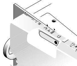
Front-Panel Indicators and Features
Figure 1-2 shows the LED indicators and components on the enclosure’s front panel (optional locking bezel not shown). Table 1-2 lists the conditions and functions indicated by each.
14 |
About Your System |
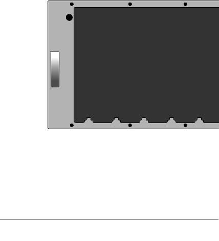
Figure 1-2. Front-Panel Features
1
2 


3 
4 
|
|
|
|
5 |
1 |
enclosure status |
2 |
power LED |
3 split mode LED (not |
|
LED |
|
|
used) |
4 |
enclosure mode |
5 |
physical disks (15) |
|
|
switch |
|
|
|
Table 1-2. Front-Panel Components
Component |
Icon |
Condition |
|
|
|
Enclosure status LED |
|
Steady amber: Power is on and enclosure is in |
(blue/amber) |
|
reset state. |
|
|
Steady blue: Power is on and enclosure status |
|
|
is OK. |
|
|
Flashing blue: Enclosure LED is being blinked |
|
|
by MD Storage Manager. |
|
|
Flashing amber: Enclosure is in fault state. |
About Your System |
|
15 |
|
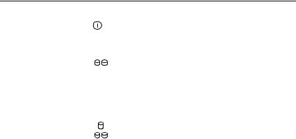
Table 1-2. Front-Panel Components (continued)
Component |
Icon |
Condition |
|
|
|
|
|
Power LED (green) |
|
|
When lit, at least one power supply is |
|
|
|
supplying power to the enclosure. |
|
|
|
|
Split mode LED (green) |
|
|
Because this mode is unused in the system, this |
|
|
|
LED should always be unlit. |
|
|
|
|
|
|
|
NOTE: This LED comes on if the enclosure mode |
|
|
|
switch on the enclosure’s front panel is in the |
|
|
|
split mode position before the enclosure is |
|
|
|
turned on. |
|
|
|
|
Enclosure mode switch |
|
|
The function of this switch is not applicable to |
|
|
|
your MD3000i. However, if additional MD1000 |
|
|
|
|
|
|
|
expansion enclosures are daisy chained to your |
|
|
|
system, the enclosure mode switch on those |
|
|
|
enclosures must be in unified-mode position. |
|
|
|
NOTE: This switch must be set prior to turning |
|
|
|
on the system. Changing the switch setting after |
|
|
|
the system is turned on will have no effect on |
|
|
|
enclosure configuration until the system goes |
|
|
|
through a complete power cycle. |
|
|
|
|
Physical Disk Carrier LED Indicators
Each physical disk carrier in your enclosure has two LEDs: an activity LED (green) and a bicolor (green/amber) status LED (see Figure 1-3). The activity LED flashes whenever the physical disk is accessed. Table 1-3 lists the flash patterns for the status LED.
16 |
About Your System |
Figure 1-3. Physical Disk Carrier LED Indicators
1 |
|
|
|
|
|
|
|
|
|
2 |
|
|
|
|
|
|
|
|
|
|
|
|
|
|
|
|
|
|
|
|
|
|
|
|
|
|
|
|
|
|
|
|
|
|
|
|
|
|
|
|
|
|
|
|
|
|
|
|
|
|
|
|
|
|
|
1 activity LED |
2 |
status LED |
Table 1-3. Physical Disk Carrier Status LEDs |
|
|
|
|
|
Status LED |
Description |
|
|
|
|
Off |
Physical disk not yet discovered by host server or an |
|
|
unsupported disk is present |
|
|
|
|
Steady green |
Physical disk is online |
|
|
|
|
Green flashing (250 milliseconds |
Physical disk is being identified |
|
[ms]) |
|
|
|
|
|
Green flashing |
Physical disk rebuilding |
|
On 400 ms |
|
|
Off 100 ms |
|
|
|
|
|
Amber flashing (125 ms) |
Physical disk failed |
|
|
|
|
Flashing green, amber, and off |
Physical disk failure predicted (SMART) |
|
|
|
|
Green 3 seconds, amber |
Physical disk rebuild aborted |
|
3 seconds, and off 3 seconds |
|
|
|
|
|
About Your System |
|
17 |
|
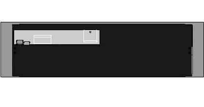
Back-Panel Indicators and Features
Figure 1-4 shows the back-panel features of the enclosure. A fully populated enclosure with dual RAID controllers and two power supply/cooling fan modules is shown. However, a single RAID controller module is supported, and the enclosure can run temporarily on one power supply/cooling fan module. For more information, see "Power Supply and Cooling Fan Features" on page 24.
Figure 1-4. Back-Panel Features
1 |
|
|
|
|
|
|
|
|
|
|
|
|
|
|
|
|
|
|
|
|
|
|
|
|
2 |
|
|
|
|
|||||||||||||||||||||||||
|
|
|
|
|
|
|
|
|
|
|
|
|
|
|
|
|
|
|
|
|
|
|
|
|
|
|
|
|
|
|
|
|
|
|
|
|
|
|
|
|
|
|
|
|
|
|
|
|
|
|
|
|
|
|
|
|
|
|
|
|
|
|
|
|
|
|
|
|
|
|
|
|
|
|
|
|
|
|
|
|
|
|
|
|
|
|
|
|
|
|
|
|
|
|
|
|
|
|
|
|
|
|
|
|
|
|
|
|
|
|
|
|
|
|
|
|
|
|
|
|
|
|
|
|
|
|
|
|
|
|
|
|
|
|
|
|
|
|
|
|
|
|
|
|
|
|
|
|
|
|
|
|
|
|
|
|
|
|
|
|
|
|
|
|
|
|
|
|
|
|
|
|
|
|
|
|
|
|
|
|
|
|
|
|
|
|
|
|
|
|
|
|
|
|
|
|
|
|
|
|
|
|
|
|
|
|
|
|
|
|
|
|
|
|
|
|
|
|
|
|
|
|
|
|
|
|
|
|
|
|
|
|
|
|
|
|
|
|
|
|
|
|
|
|
|
|
|
|
|
|
|
|
|
|
|
|
|
|
|
|
|
|
|
|
|
|
|
|
|
|
|
|
|
|
|
|
|
|
|
|
|
|
|
|
|
|
|
|
|
|
|
|
|
|
|
|
|
|
|
|
|
|
|
|
|
|
|
|
|
|
|
|
|
|
|
|
|
|
|
|
|
|
|
|
|
|
|
|
|
|
|
|
|
|
|
|
|
|
|
|
|
|
|
|
|
|
|
|
|
|
|
|
|
|
|
|
|
|
|
|
|
|
|
|
|
|
|
|
|
|
|
|
|
|
|
|
|
|
|
|
|
|
|
|
|
|
|
|
|
|
|
|
|
|
|
|
|
|
|
|
|
|
|
|
|
|
|
|
|
|
|
|
|
|
|
|
|
|
|
|
|
|
|
|
|
|
|
|
|
|
|
|
|
|
|
|
|
|
|
|
|
|
|
|
|
|
|
|
|
|
|
|
|
|
|
|
|
|
|
|
|
|
|
|
|
|
|
|
|
|
|
|
|
|
|
|
|
|
|
|
|
|
|
|
|
|
|
|
|
|
|
|
|
|
|
|
|
|
|
|
|
|
|
|
|
|
|
|
|
|
|
|
|
|
|
|
|
|
|
|
|
|
|
|
|
|
|
|
|
|
|
|
|
|
|
|
|
|
|
|
|
|
|
|
|
|
|
|
|
|
|
|
|
|
|
|
|
|
|
|
|
|
|
|
|
|
|
|
|
|
|
|
|
|
|
|
|
|
|
|
|
|
|
|
|
|
|
|
|
|
|
|
|
|
|
|
|
|
|
|
|
|
|
|
|
3 |
|
1 RAID controller |
2 RAID controller |
3 power supply/cooling |
module 0 |
module 1 |
fan modules (2) |
RAID Controller Modules
The RAID controller modules provide high-performance, advanced virtual disk configuration, and fault-tolerant disk subsystem management. Each RAID controller module contains 512 MB of cache that is mirrored with the other controller's cache for high availability and protected by a battery for up to 72 hours.
18 |
About Your System |

Each RAID controller module provides data path and enclosure management functions for your enclosure, including:
•Monitoring and controlling enclosure environment elements (temperature, fans, power supplies, and enclosure LEDs)
•Controlling access to the physical disks
•Communicating enclosure attributes and states to the host server
Each RAID controller module has dual iSCSI In ports for host access. The two iSCSI ports provide redundant host connections and support a high availability storage environment. Various configurations can be utilized, in both single controller and dual controller mode, to connect the storage enclosure to hosts depending on specific redundancy needs. For example:
•Single Path Data Configuration – The single path provides a large number of nonredundant physical connections to the array through an industry-standard Gigabit Ethernet Switch.
•Redundant Dual Path (RDP) Data Configuration – The RDP allows two separate physical paths for each client through a Gigabit Ethernet Switch. In addition, this configuration provides full redundancy through the use of either redundant disk array controller (RDAC) drivers or multipathing I/O (MPIO) drivers.
For detailed information on cabling, see the PowerVault MD3000i Installation Guide.
RAID Controller Module Connectors and Features
Figure 1-5 shows a single RAID controller module as it appears from the rear of the enclosure. RAID controller module connectors and components shown include:
•Two iSCSI In port connectors
•Management port Ethernet connector
NOTE: The RAID controller module network configuration can be assigned using a DHCP server (the default setting). If a DHCP server is not available (time-out is 10 seconds) then the RAID controller modules uses the static IP addresses of 192.168.128.101 for controller 0 and 192.168.128.102 for controller 1.
About Your System |
|
19 |
|
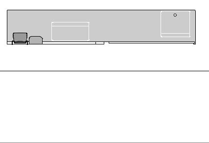
•Eleven LEDs (two iSCSI In link speed/activity, two iSCSI In link duplex mode, two Ethernet link/speed, battery fault, SAS link fault/connectivity, cache active, controller fault, and controller power)
•One SAS Out port connector
•Debug port
For a description of each component on the front panel of the RAID controller module, see Table 1-4. For an explanation of how to connect the enclosure using the RAID controller module ports, see the PowerVault MD3000i Installation Guide.
Figure 1-5. RAID Controller Module External Panel (front view)
1 |
2 |
3 |
4 |
|
5 |
|
|
6 |
7 |
8 |
9 |
10 |
|
11 |
12 13 |
14 |
15 |
16 |
||||||||||||||
|
|
|
|
|
|
|
|
|
|
|
|
|
|
|
|
|
|
|
|
|
|
|
|
|
|
|
|
|
|
|
|
|
|
|
|
|
|
|
|
|
|
|
|
|
|
|
|
|
|
|
|
|
|
|
|
|
|
|
|
|
|
|
|
|
|
|
|
|
|
|
|
|
|
|
|
|
|
|
|
|
|
|
|
|
|
|
|
|
|
|
|
|
|
|
|
|
|
|
|
|
|
|
|
|
|
|
|
|
|
|
|
|
|
|
|
|
|
|
|
|
|
|
|
|
|
|
|
|
|
|
|
|
|
|
|
|
|
|
|
|
|
|
|
|
|
|
|
|
|
|
|
|
|
|
|
|
|
|
|
|
|
|
|
|
|
|
|
|
|
|
|
|
|
|
|
|
|
|
|
|
|
|
|
|
|
|
|
|
|
|
|
|
|
|
|
|
|
|
|
|
|
|
|
|
|
|
|
|
|
|
|
|
|
|
|
|
|
|
|
|
|
|
|
|
|
|
|
|
|
|
Table 1-4. RAID Controller Module Component Functions
Item |
Component |
Icon |
Function |
|
|
|
|
1 |
iSCSI In Port 0 Link |
|
Green: Link is operating at 1000 Mbps. |
|
Speed/Activity |
|
Amber: Link is operating at 100 Mbps. |
|
Status LED |
|
|
|
|
Off: iSCSI connection is not active. |
|
|
|
|
|
|
|
|
|
2 |
iSCSI In Port 0 |
In-0 |
Provide host-to-controller iSCSI |
|
|
|
connection. If LED is solid, there is no |
activity on the link. If the LED is blinking, there is activity on the link.
3iSCSI In Port 0 Link Duplex Mode
Green: Full-duplex mode.
Off: Half-duplex mode.
NOTE: Half-duplex mode is supported only if the link speed is 100Mbps.
20 |
About Your System |
Table 1-4. RAID Controller Module Component Functions (continued)
Item |
Component |
Icon |
Function |
|
|
|
|
|
|
4 |
iSCSI In Port 1 Link |
|
|
Green: Link is operating at 1000 Mbps. |
|
Speed/Activity |
|
|
Amber: Link is operating at 100 Mbps. |
|
Status LED |
|
|
|
|
|
|
Off: iSCSI connection is not active. |
|
|
|
|
|
|
|
|
|
|
|
5 |
Battery Fault LED |
|
|
Amber: Battery backup unit or battery has |
|
(amber) |
|
|
failed or is missing. |
|
|
|
|
Off: Battery backup unit and battery is |
|
|
|
|
operating normally. |
|
|
|
|
|
6 |
Cache Active LED |
|
|
Green: On-board controller memory |
|
(green) |
|
|
contains data. |
|
|
|
|
Off: On-board controller memory is empty. |
|
|
|
|
|
7 |
iSCSI In Port 1 |
In-1 |
Provide host-to-controller iSCSI |
|
|
|
|
|
connection. If LED is solid, there is no |
|
|
|
|
activity on the link. If the LED is blinking, |
|
|
|
|
there is activity on the link. |
|
|
|
|
|
8 |
iSCSI In Port 1 Link |
|
|
Green: Full-duplex mode. |
|
Duplex Mode |
|
|
Off: Half-duplex mode. |
|
|
|
|
|
|
|
|
|
NOTE: Half-duplex mode is supported only if |
|
|
|
|
the link speed is 100Mbps. |
|
|
|
|
|
9 |
Controller Fault |
|
|
Amber: Controller fault detected. |
|
LED (amber) |
|
|
Off: Controller is operating normally. |
|
|
|
|
|
|
|
|
|
|
10 |
Controller Power |
|
|
Green: Controller power is on. |
|
LED (green) |
|
|
Off: Controller is not powered. |
|
|
|
|
|
|
|
|
|
|
11 |
Ethernet Link LED |
|
|
Green: Ethernet connection is active. |
|
(green) |
|
|
Off: Ethernet connection is not active. |
|
|
|
|
|
|
|
|
|
|
12 |
Management Port |
|
|
Provide a 10/100 Mbps Ethernet |
|
Ethernet Connector |
|
|
connection for out-of-band management of |
|
|
|
|
the enclosure. |
About Your System |
|
21 |
|

Table 1-4. RAID Controller Module Component Functions (continued)
Item |
Component |
Icon |
Function |
|
|
|
|
|
|
13 |
Ethernet Speed |
|
|
Green: Ethernet connection is operating at |
|
LED (green) |
|
|
100 Mbps. |
|
|
|
|
Off: Ethernet connection is operating at |
|
|
|
|
10 Mbps or is not active. |
|
|
|
|
|
14 |
Debug Port |
|
|
Dell support only. |
|
|
|||
|
|
|
|
|
|
|
|
|
|
15 |
SAS Link Fault |
|
|
Amber: Between 1–3 links are connected. |
|
LED |
|
|
Green: All four links are connected. |
|
|
|
|
|
|
|
|
|
Off: All links are down. |
|
|
|
|
|
16 |
SAS Out Port |
Out |
Provides SAS connection for cabling to a |
|
|
|
|
|
downchain expansion enclosure. |
|
|
|
|
|
The RAID controller module connects to the enclosure midplane via the two midplane connectors on its internal (rear) panel. The RAID controller module is shown in Figure 1-6.
Figure 1-6. RAID Controller Module
1
2 


1 |
battery cover |
2 |
midplane connectors (2) |
22 |
About Your System |

Battery Backup Unit
Each RAID controller contains a three-cell lithium-ion battery backup unit (BBU) that powers the controller’s cache memory and preserves the cache contents in the event of a power outage of up to 72 hours. The RAID controller firmware performs a test of the BBU at startup and will illuminate the battery fault LED if the battery is not operating within specified ranges, or if the battery is missing. The battery begins recharging automatically if the test determines that it is necessary. For a description of the battery fault LED, see Table 1-4. For information on removing and installing the BBU, see "Removing and Installing a RAID Controller Module Backup Battery Unit" on page 62.
NOTE: For virtual disks, the RAID controller firmware changes the data cache setting based on the state of the battery. If the battery is missing or does not have sufficient charge, the controller flushes the cache and sets the write cache attribute to Write Through for all virtual disks. When the battery is replaced, Write Back is reenabled.
The RAID controller module logs the age of the battery and issues a replacement reminder message approximately six weeks before expiration. After replacing the battery, you must use MD Storage Manager to reset the battery age.
RAID Enclosure Thermal Shutdown
Enclosure management provides a feature that automatically shuts down the enclosure when the temperature within the storage enclosure exceeds a safe threshold. Thermal shutdown protects the data on the physical disks from corruption in the event of cooling system failure. Because the battery backup unit protects against cache data loss for up to 72 hours, all data in the cache is saved. It is not necessary to shut down any expansion enclosures attached to the storage enclosure.
Temperature threshold values are used to determine the temperature at which shutdown occurs. These thresholds are default settings and cannot be changed. If the temperature sensors on the backplane detect a temperature exceeding the Nominal Failure Threshold, a critical event is set. If the Maximum Failure Threshold is reached, shutdown of the enclosure power supplies occurs within 3 minutes. A third threshold, the Shutdown Threshold, shuts down the enclosure power supplies within 5 seconds after it is reached.
About Your System |
|
23 |
|

Cache Functions and Features
Cache Mirroring
The cache mirroring function copies accepted host-write data from the primary controller to the partner controller. This action ensures that hostwrite data is safely mirrored to the partner controller before successful completion status is returned to the host. If a controller fails, the surviving controller safely retains all mirrored data. Cache mirroring is enabled by default.
Write-Back Cache
Write-back cache is a caching strategy whereby write operations result in a completion signal being sent to the host operating system as soon as the cache receives the data to be written. The target physical disk will receive the data at a more appropriate time in order to increase controller performance. In dual-active controller configurations with write-back caching enabled, the write data is always copied to the cache of the second controller before completion status is issued to the host initiator. Write Back is enabled by default.
Write-Through Cache
Write-through cache is a caching strategy whereby data is written to the physical disk before completion status is returned to the host operating system. Write-through cache is considered more secure than write-back cache, since a power failure is less likely to cause loss of data. The RAID controller automatically switches to write-through if cache mirroring is disabled or if the battery is missing or has a fault condition.
NOTE: Write cache settings are not user-configurable.
Power Supply and Cooling Fan Features
Your RAID enclosure supports two integrated, hot-pluggable power supply/cooling fan modules. Both modules must be installed to ensure proper cooling. Each module contains two separate cooling fans. The enclosure requires at least three of the cooling fans to operate to avoid overheating.
24 |
About Your System |
CAUTION: A power supply/cooling fan module can be removed from a poweredon enclosure for a maximum period of no more than 5 minutes. Beyond that time, the enclosure may automatically shut down to prevent damage to the enclosure and/or enclosure components.
A power supply/cooling fan module can be replaced without powering down the enclosure. For information on removing and replacing the modules, see "Removing and Installing the Power Supply/Cooling Fan Module" on page 64.
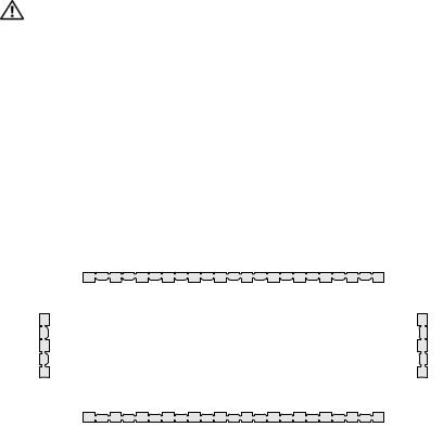
Figure 1-7 shows the power supply/cooling fan module features and LED indicators. Table 1-5 lists the LED indicator descriptions.
Figure 1-7. Power Supply and Cooling Fan Module LED Features and Indicators
1 |
2 |
3 |
4 |
|
|
|
|
|
|
|
|
|
|
||||||||||||
|
|
|
|
|
|
|
|
|
|
|
|
|
|
|
|
|
|
|
|
|
|
|
|
|
|
|
|
|
|
|
|
|
|
|
|
|
|
|
|
|
|
|
|
|
|
|
|
|
|
|
|
|
|
|
|
|
|
|
|
|
|
|
|
|
|
|
|
|
|
|
|
|
|
|
|
|
|
|
|
|
|
|
|
|
|
|
|
|
|
|
|
|
|
|
|
|
|
|
|
|
|
|
|
|
|
|
|
|
|
|
|
|
|
|
|
|
|
|
|
|
|
|
|
|
|
|
|
|
|
|
|
|
|
|
|
|
|
|
|
|
|
|
|
|
|
|
|
|
|
|
|
|
|
|
|
|
|
|
|
|
|
|
|
|
|
|
|
|
|
|
|
|
|
|
|
|
|
|
|
|
|
|
|
|
|
|
|
|
|
|
|
|
|
|
|
|
|
|
|
|
|
|
|
|
|
|
|
|
|
|
|
|
|
|
|
|
|
|
|
|
|
|
|
|
|
|
|
|
|
|
|
|
|
|
|
|
|
|
|
|
|
|
|
|
|
|
|
|
|
|
|
|
|
|
|
|
|
|
|
|
6 |
|
|
|
5 |
1 |
DC power LED |
2 |
Power supply/cooling fan |
3 |
AC power LED |
|
|
|
fault LED |
|
|
4 |
cooling fans (2) |
5 |
on/off switch |
6 |
AC power connector |
About Your System |
|
25 |
|
Table 1-5. Power Supply/Cooling Fan Module LED Indicators
Type |
Color |
Icon |
Function |
|
|
|
|
DC power |
Green |
|
On: DC output voltages are within |
|
|
|
specifications. |
|
|
|
Off: No power or voltages not within |
|
|
|
specifications. |
|
|
|
|
Power |
Amber |
|
On: DC output voltages are not within |
supply/cooling |
|
|
specifications or one (or both) fans are in fault. |
fan fault |
|
|
Off: No fault condition is present. |
|
|
|
|
|
|
|
|
AC power |
Green |
|
On: AC input voltage is within specifications. |
|
|
|
Off: No power or voltages not within |
|
|
|
specifications. |
|
|
|
|
26 |
About Your System |

Using Your RAID Enclosure
This section covers the following information:
•Basic concepts of a RAID solution including physical disks, virtual disks, and disk groups
•RAID levels supported by MD Storage Manager
•Hot spare operations and rebuilds
•Media errors and unreadable sectors
•RAID operations and features
•Advanced RAID features
•Hardware redundancy and failover including cabling
•Updating enclosure firmware
•Best practice recommendations
Physical Disks, Virtual Disks, and Disk Groups
Physical disks in your RAID array provide the physical storage capacity for your data. Before you can begin writing data to the storage array, you must configure the physical storage capacity into logical components, called disk groups and virtual disks.
A disk group is a set of physical disks upon which multiple virtual disks are created. The maximum number of physical disks supported in a disk group is 30. You create disk groups from unconfigured capacity on your storage array.
A virtual disk is a partition in a disk group that is made up of contiguous data segments of the physical disks in the disk group. A virtual disk consists of data segments from all physical disks in the disk group. Virtual disks and disk groups are set up according to how you plan to organize your data. For example, you might have one virtual disk for inventory, a second virtual disk for financial and tax information, and a third virtual disk for customer information.
Using Your RAID Enclosure |
|
27 |
|

All virtual disks in a disk group support the same RAID level. The RAID enclosure supports up to 256 virtual disks (minimum size of 10 MB each) that can be assigned to host servers. Each virtual disk is assigned a Logical Unit Number (LUN) that is recognized by the host operating system.
Physical Disks
Only Dell-supported 3.0-Gbps SAS physical disks are supported in the storage array. If the RAID controller module detects unsupported physical disks, it marks the disk as unsupported and the physical disk becomes unavailable for all operations.
NOTE: The MD3000i enclosure must contain at least two physical disks for proper operation. This is necessary because the physical disks are used to store configuration information.
Physical Disk States
The RAID controller module recognizes the physical disk states (mode and status reported in MD Storage Manager) described in Table 2-1.
Table 2-1. RAID Controller Physical Disk States
Status |
Mode |
Description |
Physical Disk |
|
|
|
Status LED |
|
|
|
Indication |
|
|
|
|
Optimal |
Unassigned |
The physical disk in the indicated |
Steady Green |
|
|
slot is unused and available to be |
|
|
|
configured. |
|
|
|
|
|
Optimal |
Assigned |
The physical disk in the indicated |
Steady Green |
|
|
slot is configured as part of a disk |
|
|
|
group. |
|
|
|
|
|
Optimal |
Hot Spare Standby |
The physical disk in the indicated |
Steady Green |
|
|
slot is configured as a hot spare. |
|
|
|
|
|
Optimal |
Hot Spare In Use |
The physical disk in the indicated |
Steady Green |
|
|
slot is in use as a hot spare within |
|
|
|
a disk group. |
|
28 |
Using Your RAID Enclosure |

Table 2-1. RAID Controller Physical Disk States (continued)
Status |
Mode |
Description |
Physical Disk |
|
|
|
Status LED |
|
|
|
Indication |
|
|
|
|
Failed |
Assigned, |
The physical disk in the indicated |
Amber flashing |
|
Unassigned, Hot |
slot has been failed because of an |
(125 ms) |
|
Spare In Use, or |
unrecoverable error, an incorrect |
|
|
Hot Spare Standby |
drive type or drive size, or by its |
|
|
|
operational state being set to |
|
|
|
failed. |
|
|
|
|
|
Replaced |
Assigned |
The physical disk in the indicated |
Green flashing |
|
|
slot has been replaced and is ready |
(On 400 ms, Off |
|
|
to be, or is actively being, |
100 ms) |
|
|
configured into a disk group. |
|
|
|
|
|
Pending |
Assigned, |
A SMART error has been detected |
Flashing Green, |
Failure |
Unassigned, Hot |
on the physical disk in the |
Amber, and off |
|
Spare In Use, or |
indicated slot. |
|
|
Hot Spare Standby |
|
|
|
|
|
|
(none) |
(none) |
The indicated slot is empty, or the |
Off |
|
|
array cannot detect the physical |
|
|
|
disk. |
|
|
|
|
|
If a disk drive rebuild fails because of a source drive failure or because the drive is too small, the user interface reports a failure of the physical disk even though the LED state on the drive indicates the rebuild was aborted (green for 3 seconds, amber for 3 seconds, then off for 3 seconds).
Self-Monitoring Analysis and Reporting Technology (SMART)
Self-Monitoring Analysis and Reporting Technology (SMART) monitors the internal performance of all physical disk components to detect faults indicating the potential for physical disk failure. SMART uses this information to report whether failure is imminent so that a physical disk can be replaced before failure occurs. The RAID controller monitors all attached drives and notifies users when a predicted failure is reported by a physical disk.
Using Your RAID Enclosure |
|
29 |
|

Virtual Disks and Disk Groups
When configuring a storage array, you would normally proceed in this order:
•Organize the physical disks into disk groups.
•Create virtual disks within these disk groups.
•Determine which host servers you want to grant access to which virtual disks, then create mappings to associate the virtual disks with the host servers.
NOTE: Host server access must be created prior to mapping virtual disks to them.
Disk groups are always created in the unconfigured capacity of a storage array; virtual disks are created within the free capacity of a disk group. Unconfigured capacity is comprised of the available physical disk space that is not already assigned in the storage array. Free capacity is the space in a disk group that has not been assigned to a virtual disk.
Creating a Virtual Disk
To create a virtual disk, use one of the following methods:
•Create a new disk group from unconfigured capacity. You can define the RAID level and capacity (the number of physical disks) for the disk group, then define the parameters for the first virtual disk in the new disk group.
•Create a new virtual disk in the free capacity of an existing disk group. You only need to specify the parameters for the new virtual disk.
Virtual Disk States
The RAID controller module recognizes the following virtual disk states.
Table 2-2. RAID Controller Virtual Disk States
State |
Description |
|
|
Optimal |
The virtual disk contains physical disks that are all online. |
|
|
Degraded |
The virtual disk with a redundant RAID level contains an inaccessible |
|
physical disk. The system can still work properly, but performance may |
|
be affected and additional disk failures may result in data loss. |
|
|
Offline |
A virtual disk with one or more member disks in an inaccessible (failed, |
|
missing, or offline) state. Data on the virtual disk is no longer |
|
accessible. |
|
|
30 |
Using Your RAID Enclosure |
Loading...