


HydroPower TF250-8G(10H)
Bosch HydroPower TF250-8G(10H), HydroPower TF325-8G(13H), HydroPower TF400-8G(16H) Installation Manual And Operating Instructions
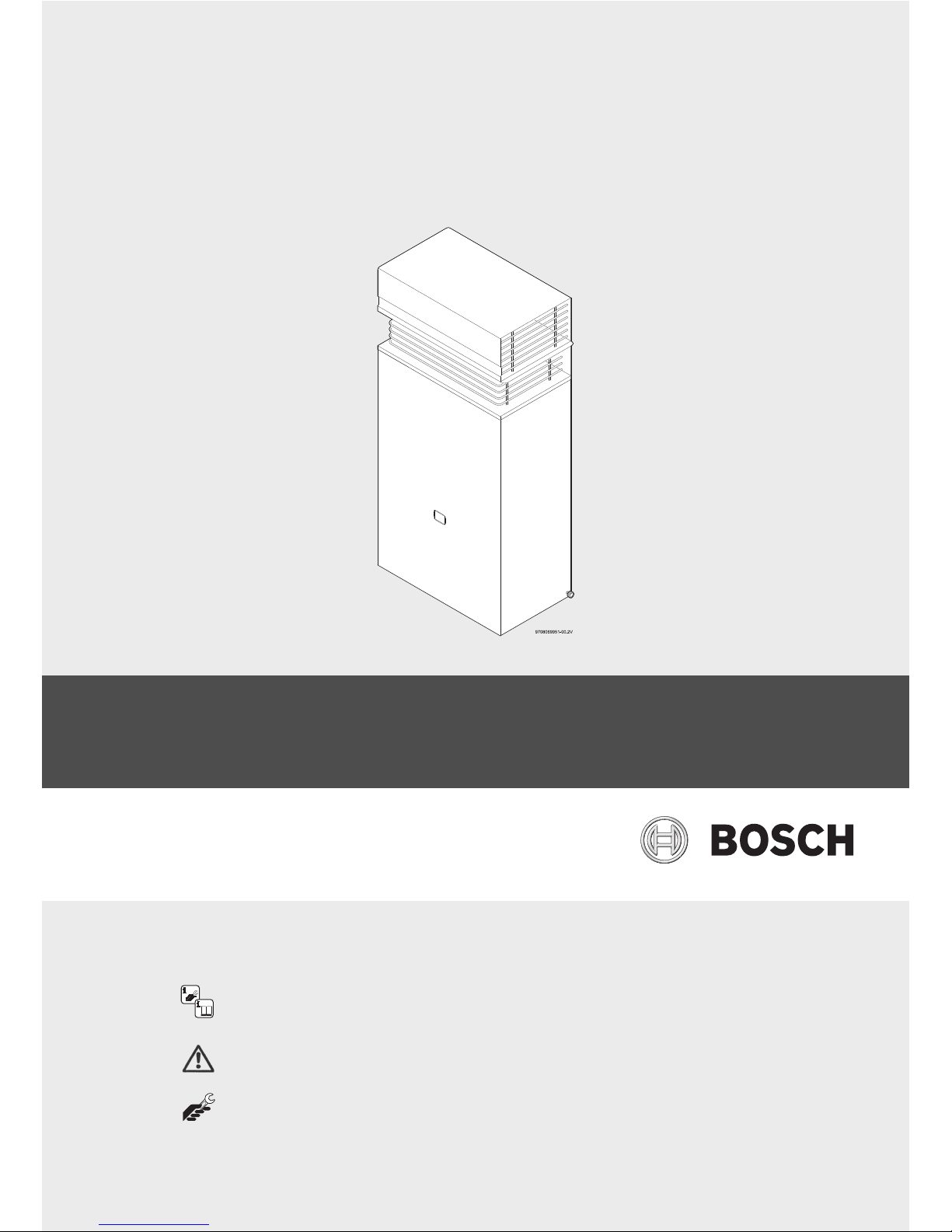
Installation Manual and Operating Instructions
Continuous Flow Gas Water Heaters (External Models)
HydroPower
TF250-8G(10H)/ TF325-8G(13H)/ TF400-8G(16H)
8 716 473 071 (2015/04) AU
Read installation manual prior to installation of this unit!
Read user manual before putting this unit in operation!
Observe the warnings in the manuals!
The installation room must fulfill the ventilation requirements!
Installation by an authorised person only!

8 716 473 071 (2015/04) HydroPower
2 | Table of contents
Table of contents
1 Safety information and symbols . . . . . . . . . . . . . . . . 3
1.1 Key to symbols . . . . . . . . . . . . . . . . . . . . . . . 3
1.2 Safety information . . . . . . . . . . . . . . . . . . . . . 3
2 Technical Characteristics and Dimensions . . . . . . . 4
2.1 General Description . . . . . . . . . . . . . . . . . . . 4
2.2 Explanation of Model Code . . . . . . . . . . . . . . 4
2.3 Package contents . . . . . . . . . . . . . . . . . . . . . 4
2.4 Product overview . . . . . . . . . . . . . . . . . . . . . 4
2.5 Description of the Hot Water Unit . . . . . . . . 4
2.6 Dimensions . . . . . . . . . . . . . . . . . . . . . . . . . . 6
2.7 Electrical scheme . . . . . . . . . . . . . . . . . . . . . 7
2.8 Technical characteristics . . . . . . . . . . . . . . . 7
3 Regulations . . . . . . . . . . . . . . . . . . . . . . . . . . . . . . . . . . 8
4 Installation . . . . . . . . . . . . . . . . . . . . . . . . . . . . . . . . . . 8
4.1 Important information . . . . . . . . . . . . . . . . . . 9
4.2 Requirements of the installation location . 10
4.3 Hot Water Unit mounting . . . . . . . . . . . . . . 11
4.4 Water connection . . . . . . . . . . . . . . . . . . . . 12
4.5 Gas connection . . . . . . . . . . . . . . . . . . . . . . 12
4.6 Testing . . . . . . . . . . . . . . . . . . . . . . . . . . . . . 12
5 Commissioning . . . . . . . . . . . . . . . . . . . . . . . . . . . . . . 12
5.1 Before starting up the heater . . . . . . . . . . . 12
5.2 Remove the front cover . . . . . . . . . . . . . . . . 12
5.3 Inlet pressure adjustment . . . . . . . . . . . . . . 13
5.4 Burner pressure adjustment . . . . . . . . . . . . 13
5.5 Conversion to a different type of gas . . . . . 14
6 Operating instructions . . . . . . . . . . . . . . . . . . . . . . . 14
6.1 Consumer gas adjustment . . . . . . . . . . . . . 14
6.2 Consumer temperature/flow adjustment . 14
7 Maintenance . . . . . . . . . . . . . . . . . . . . . . . . . . . . . . . . 15
8 Troubleshooting . . . . . . . . . . . . . . . . . . . . . . . . . . . . . 16
8.1 Problem/cause/solution . . . . . . . . . . . . . . . 16
9 Environmental protection . . . . . . . . . . . . . . . . . . . . 17
10 Water quality . . . . . . . . . . . . . . . . . . . . . . . . . . . . . . . 18
11 Warranty details . . . . . . . . . . . . . . . . . . . . . . . . . . . . 19
8 716 473 071 (2015/04)HydroPower
Safety information and symbols | 3
1 Safety information and symbols
1.1 Key to symbols
Warnings
The following keywords are defined and used in this document:
• NOTICE indicates a situation that could result in damage to
property or equipment.
• CAUTION indicates a situation that could result in minor to
medium injury.
• WARNING indicates a situation that could result in severe
injury or death.
• DANGER indicates a situation that will result in severe
injury or death.
Important information
Additional symbols
1.2 Safety information
If you smell gas:
▶ Close the gas supply valve to the appliance.
▶ Isolate gas supply from gas meter or LPG bottle.
▶ Do not operate any electrical appliances or switches (on/
off).
▶ Extinguish other sources of ignition.
▶ Go to a different location and call the gas supplier or an
authorised technician in order to check the gas supply.
If you notice dark combustion gases or sooting:
▶ Isolate the Gas supply to the heater.
▶ Notify an authorised technician.
Installation, Assembly and Modifications
▶ The installation, assembly and modifications to the heater
must only be performed by an authorised installer.
Maintenance
▶ The water heater is required to have a service and safety
inspection every two years.
▶ The Installer is responsible for the safety and
environmental compatibility of the installation.
▶ The Owner/User is responsible for keeping the area around
the water heater free from debris.
▶ Safe access to inspect and service the water heater is the
responsibilty of the property owner.
▶ Only original spare parts must be used, supplied by an
authorised distributor of Genuine Bosch parts.
Explosive and highly flammable material
▶ Do not store or use flammable material (paper, spray cans,
solvents, paints, etc) near the heater.
Combustion air and surrounding air
▶ To avoid corrosion, the combustion air and surrounding air
must be free from harmful substances.
▶ Do not spray aerosols or use chemicals around the heater
unless heater is isolated. (All valves closed).
Risk of damage due to operator error
Operator errors can result in injury and damage to property.
▶ Ensure that children never operate this appliance
unsupervised.
▶ Ensure that only personnel who can operate this appliance
correctly have access to it.
▶ Refer to the operating and user instructions before
adjusting the water heater.
To be installed and serviced only by an authorised person
The “authorised installing person” is responsible for:
▶ Correct installation and commissioning of this appliance.
▶ Ensuring the appliance performs to the specifications
stated on the rating label.
▶ Demonstrating the operation of the appliance to the
customer before leaving.
▶ Handing these instructions to customer.
THIS APPLIANCE IS NOT SUITABLE FOR POOL, SPA POOL OR
SOLAR BOOSTER APPLICATION.
NOT SUITABLE FOR COMMERCIAL BOOSTING OF A WARM
WATER RECIRCULATION SYSTEM.
Warnings in this document are identified by
a warning triangle printed against a grey
background.
Keywords at the start of a warning indicate
the type and seriousness of the ensuing risk
if measures to prevent the risk are not taken.
This symbol indicates important information
where there is no risk to people or property.
Symbol Explanation
▶ Step in an action sequence
Cross-reference to another part of the document
•List entry
– List entry (second level)
Table 1
8 716 473 071 (2015/04) HydroPower
4 | Technical Characteristics and Dimensions
2 Technical Characteristics and Dimensions
2.1 General Description
2.2 Explanation of Model Code
2.3 Package contents
•Gas hot water unit
• Documentation
2.4 Product overview
HydroPower Ignition is exclusive to Bosch - it does not require
a 240V power supply.
• HydroPower uses the energy created by the water flow to
ignite the burner and begin the heating process. The unit
only starts when a hot water tap is opened. Once the tap is
turned off, the unit turns off.
2.5 Description of the Hot Water Unit
• Hot Water Unit for external wall-mounting only
• Available in Natural gas or LP gas
• Hydrogenerator produces sufficient energy to ignite and
control the heater
– Water enters the Hydrogenerator
– The turbine spins with water flow
– A voltage is generated by the turbine
– This voltage causes the ignition control unit to light a
temporary pilot
– The water pressure opens the main burner gas valve
and the pilot ignites the main burner, the pilot then
goes out
– The water flows through the heat exchanger where it is
heated
•Safety devices:
– Flame rod to check for accidental extinction of the
burner flame
– Overtemperature switch to prevent overheating.
• Water filter on the inlet water supply
Economical
Only heating water when required, the Bosch range is
extremely economical to run.
Versatile
LPG models are particularly popular in country areas, where
Natural Gas is not available.
Low Temperature Areas
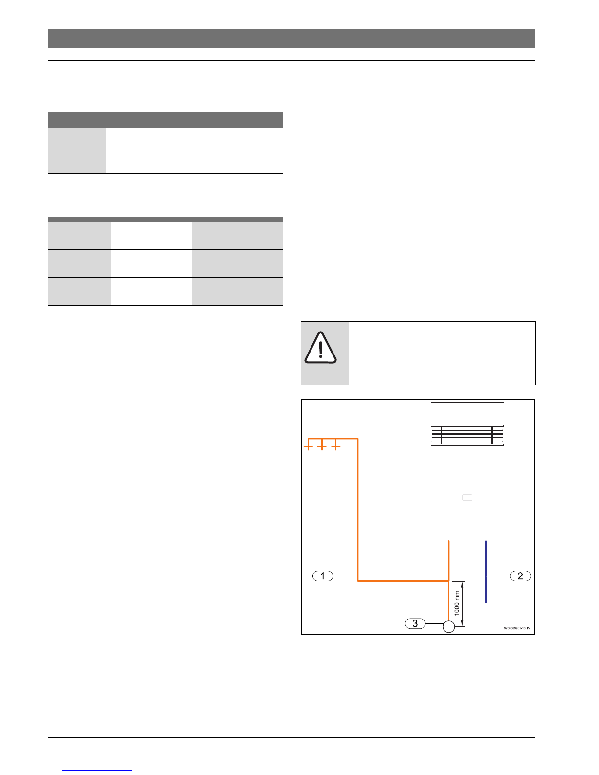
In areas where the atmospheric temperature may drop to 0 °C
for brief periods, the installation of an EXOGEL valve (part
number H707 060 151) will minimise the possibility of
damage to the appliance if the water freezes.
Fig. 1 EXOGEL valve
[1] Hot water
[2] Cold water
[3] EXOGEL valve
Models Bosch Hydropower TF250/325/400
Category CONTINUOUS FLOW
Type GAS - EXTERNAL INSTALLATION
Table 2
TF (Top Flue) 250 (10 litres/min
@ 25 °C Rise)
G (Hydrogenerator)
TF (Top Flue) 325 (13 litres/min
@ 25 °C Rise)
G (Hydrogenerator)
TF (Top Flue) 400 (16 litres/min
@ 25 °C Rise)
G (Hydrogenerator)
Table 3
NOTICE:
This water heater MUST NOT be installed in
areas where the temperature remains below
0 °C for extended periods.

8 716 473 071 (2015/04)HydroPower
Technical Characteristics and Dimensions | 5
Low Flow Rates
This gas water heater is designed to operate at a minimum flow
rate between 3.2 to 4.0 litres per minute. Sufficient flow must
be provided to ensure the correct operation of the appliance.
There are various causes of a low flow rate including, but not
limited to:
• Low flow tapware
• Flow restrictors/aerators
•Hand held showers
• Poor inlet pressure to property
• Restrictive pipework and/or fittings
Water fixtures with a flow rate of 7.5 litres per min for hand
basins and 9 litres per min for shower roses are recommended.
Failure of the unit to operate correctly due to poor flow rate will
not be covered by warranty.
8 716 473 071 (2015/04) HydroPower
6 | Technical Characteristics and Dimensions
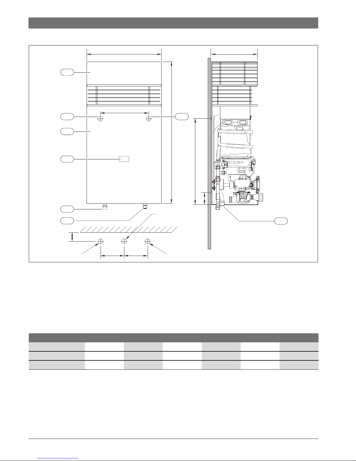
2.6 Dimensions
Fig. 2
[1] Top flue
[2] Front cover
[3] Inspection window
[4] Wall mounting point
[5] Cold water inlet
[6] Gas inlet
[7] Hot water outlet
265
B
9708069951-01.2V
A
C
E
2
D
3
6
1
50
120120
Ø1/2" Ø1/2"
NG: Ø3/4"
LPG: Ø1/2"
4 4
7
5
Dimensions (mm) A B C D E Weight (kg)
TF250(10H) 405 845 533 240 68 21
TF325(13H) 405 845 533 240 68 22
TF400(16H) 460 936 533 240 82 25
Table 4 Dimensions
8 716 473 071 (2015/04)HydroPower
Technical Characteristics and Dimensions | 7
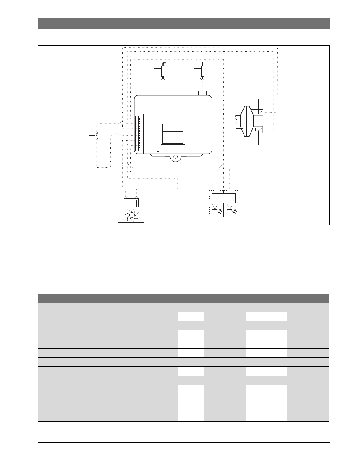
2.7 Electrical scheme
Fig. 3
[1] Main Solenoid Valve
[2] Diaphragm Switch
[3] Pilot Solenoid Valve
[4] Ionisation electrode (Flame Rod)
[5] Ignition electrode (Spark Electrode)
[6] Temperature limiter
[7] Hydrogenerator
[8] LED (green)
[9] LED (red)
2.8 Technical characteristics
45
3
1
2
9
6
8
SHV
9708069951-11.1V
7
Technical characteristics Units TF250H / 10H TF325H / 13H TF400H / 16H
Gas Consumption
Nominal Gas Consumption MJ/h 79 104 130
Supply pressure flowing
Natural gas (When operating) kPa 1.13 1.13 1.13
LP gas (When operating) kPa 2.75 2.75 2.75
Number of injectors 12 14 18
Water data
Maximum permissible pressure (Static) kPa 800 800 800
Temperature selector in fully clockwise position
Temperature rise (Above incoming water temperature) °C 50 50 50
Water flow range (Litres per minute) l/min 3.2 to 5 3.2 to 6.5 3.2 to 8
Minimum operating water pressure kPa 30 40 50
Minimum constant water pressure for minimum flow kPa 60 100 130
Table 5
8 716 473 071 (2015/04) HydroPower
8 | Regulations
3Regulations
All local by-laws and regulations pertaining to installation and
use of gas appliances must be observed.
This appliance must be installed in accordance with the
manufacturers installation instructions, AS/NZS5601, AS/
NZS3500 and all Local Building & Gas fitting regulations.
This appliance must not be installed indoors or in an enclosed
space. This appliance is approved for outdoor installation only.
Do not install this appliance with any modification or alteration.
Failure to install this appliance in accordance with these
installation instructions will void the warranty and may create
an unsafe situation.
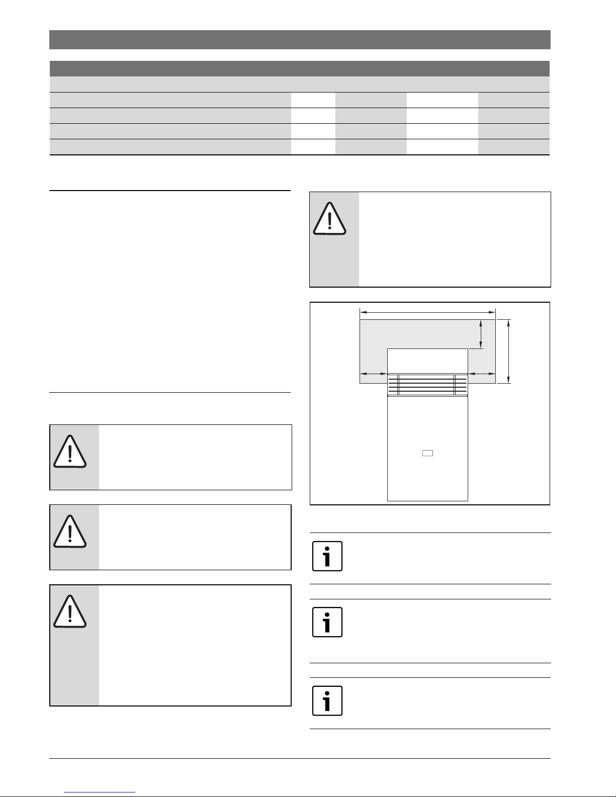
4 Installation
Fig. 4 Heat shield
Temperature selector in fully anti-clockwise position
Temperature rise (Above incoming water temperature) °C 25 25 25
Water flow range (Litres per minute) l/min 4 to 10 4 to 13 4 to 16
Minimum operating water pressure kPa 45 45 45
Minimum constant water pressure for maximum flow kPa 100 140 170
Technical characteristics Units TF250H / 10H TF325H / 13H TF400H / 16H
Table 5
DANGER:
This appliance must not be installed indoors
or in an enclosed space in accordance with
AS/NZS5601.
DANGER: Explosion Risk!
▶ Always turn off the gas valve before
carrying out any work on components
which carry gas.
DANGER: Appliance malfunction!
This appliance must be installed with no
obstructions to air entry openings at the
front, rear, side, or top.
▶ Periodic checking of openings to ensure
no blockage or obstruction of the air
openings from plants, debris, or insects
must be carried out.
NOTICE: Property damage!
If the appliance is to be installed on a
combustible surface:
▶ Use a heat shield as per AS/NZS5601 -
accessory
9 708 061 400.ZG1 ( Fig. 4).
The installation and the initial startup are to
be carried out only by an authorised person.
Not suitable for pool, spa pool, or solar
booster application.
Not suitable for commercial boosting of a
warm water recirculation system.
This appliance should only be installed in
applications where incoming cold water
temperature does not exceed 40 °C.
400 mm
850 mm
230 mm
=
9708069951-12.1V
=
 Loading...