


HP270-2
DOMESTIC HOT WATER
HEAT PUMP 200 / 250 / 270 L
This document is confidential and restricted to exclusive use by the official technical
assistance of Bosch in the countries of destination of this product.
TECHNICAL MANUAL FOR AFTER SALES AND
SERVICE TECHNICIANS

Page 2 from 56 6-720-821-364 SM HP270 – 250 - 200 2016/12 en
1) Introduction
Domestic Hot Water Heat Pumps (DHW-HP), with or without air connections ducts, use the heat existing in the
surrounding air, or the wasted heat from the indoor air, as energy source for DHW preparation.
This model of domestic hot water heat pump provides hot water for residential purposes, using a closed refrigerant
unit filled with R134a. This ensures the energy production taking out the energy from the air – the cold source –
and delivers the energy to a secondary circuit – the water – where a simple circulation pump, ensures the water
movement through a plate heat exchanger, heating the water that is stored in a tank.
2) Working Principle
There are 2 variants of heat pumps, depending on the working conditions:
- Positive working temperatures: +5ºC / +35ºC
- Negative working temperatures: -10ºC / +35ºC
Note: In case the air temperature is out of the specified working range, the appliance automatically activates the
electrical back up (if in Combi mode). One hour after the warning display (HOT or COLD) has appeared; the
appliance checks the air temperature and, in case it is within the range values, returns to heat pump mode
operation.
The control loop for air temperature check is done every hour, while the electrical backup is in operation.
Stand-by mode
HMI actuation
LCD Backlight ON
Active Operation Mode
(default from factory: combi mode + manual operation)
LCD Backlight OFF
(after 15 sec without any selection)
Current Temperature of the Tank
(measured at the top)
Clock & Day Function
(defined at start up and/or current day and hour)
Temperature Selection
(default from factory = 50ºC)
(except FD>555: software
Temperature Blinks
until confirmation with
OK button
Temperature remains as
previous after 10 sec in
case of any other selection
Page 3 from 56 6-720-821-364 SM HP270 – 250 - 200 2016/12 en
2.1) Operation Modes
Operation Modes (HP 270-2)
Comment
Combi Mode
(default selection from factory)
T
set
= 50ºC / 54ºC (default value depends
software version)
Temperature adjustment: 30ºC to 70ºC
Heat Pump Mode
Temperature adjustment: 30ºC to 60ºC
Electric Heater Mode
Temperature adjustment: 30ºC to 70ºC
New Platform (HP270-3 and HP200/250-1)
Combi Mode
(default selection from factory)
Standby
Operation
T
set
= 53ºC
Temperature adjustment: 30ºC to 70ºC
Economic Mode
Temperature adjustment: 30ºC to 60ºC
Electric Heater Mode
Temperature adjustment: 30ºC to 70ºC
Table 1 – Operation Modes
Conditions for operation:
The heat pump compressor is activated according to the following conditions and control unit settings,
nevertheless, following sequence is always verified when connecting to the main power, when an error code is
reseated or the appliance stops due to reaching the selected temperature.
In the current service manual version, the software specific functions are indicated according Software Version at
control unit identification sticker.
0 – 1 min: Water Pump
ON
1 – 3 min: Standby (Duct off)
or
1 – 2 min: Standby (Duct on)
3 – 4 min: Fan activation when
Duct OFF
or
2 – 4 min: Fan activation when
> 4 min: Compressor and water
pump activation
Page 4 from 56 6-720-821-364 SM HP270 – 250 - 200 2016/12 en
From FD ≥ 306 (June 2013) until FD ≤ 453 (May 2014):
HPAF0501 (-10ºC / + 35ºC models)
HPAF0701 (+5ºC / +35ºC models)
Operation Mode described during manual.
From FD ≥ 454 (June 2014):
HPAF0502 (-10ºC / + 35ºC models)
HPAF0702 (+5ºC / +35ºC models)
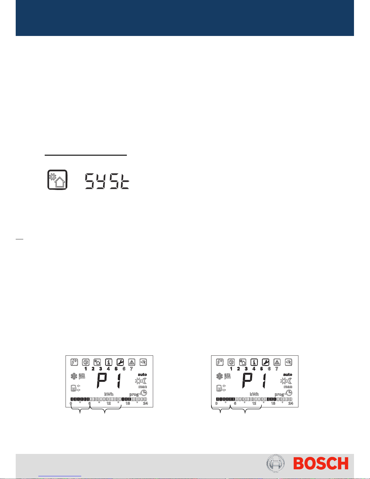
Changes done in new version:
- “Syst” message indication in case of detection of PV energy production;
+
- Introduction of new parameter “Rcir” (see IM) for software information about existence of external recirculation of
domestic hot water;
- E09 / E11 lockout activates automatically electrical heater to ensure minimum 40ºC hot water in tank (in combi or
in heat pump mode).
From FD ≥ 555 (July 2015):
HPAF0503 (-10ºC / + 35ºC models)
HPAF0703 (+5ºC / +35ºC models)
o Set Point – default set point of 50ºC was changed to 54ºC due to ErP directive;
o Operation in Automatic Mode – in previous version was not possible to deactivate the external booster
heater (boiler = boil ON) according the defined automatic program mode (P1, P2, P3) in combination with
boiler. The boiler did not switch off after reaching the set point and the correction was using only manual mode.
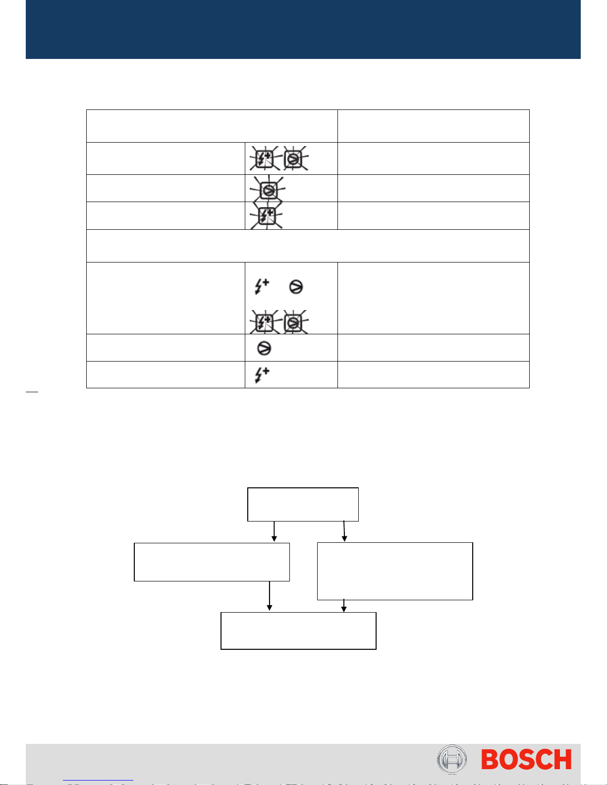
o Full Mode – the manual (FULL) activation will have from now on, priority even in inactivity periods defined in
P1 / P2 / P3.
Current New
Pict.1 – Behaviour of FULL = Compressor + E-heater / Compressor + Boiler
ON
OFF
ON
ON
Page 5 from 56 6-720-821-364 SM HP270 – 250 - 200 2016/12 en
o Comfort Improvement – to improve comfort a waiting time was introduced, so while heating, the appliance will
be able to detect if the user is tapping water. In situations where the storage tank has an uniform temperature
near the set point and a tapping is detected, the heat pump will stop for 1 hour to maximize the use of hot water
in top part.
o Changes in Air Defrost sequence
(Attention: only +5ºC / +35ºC model)
Current Behavior:
Air defrost sequence is activated during 10 min with fan On and compressor Off when 5ºC < T
air
(3d) < 10ºC for
more than 60 min and compressor is ON for more than 60 min. The number of air defrost (8d) will depend on other
conditions listed in this manual.
This new software version brings additionally an air defrost sequence activated during 45 min when 0ºC < T
air
<
5ºC, as due to ErP directive and to decrease electrical consumption for cold climate the appliance wilkl be allowed
to operate when possible below minimum limit.
2.2) HMI Configuration (see Installation Manual for details)
HP 270-2: From FD ≥ 306 (June 2013) until FD ≤ 660 (Dec 2016):
HPAF0501 / 0502 / 0503 (-10ºC / + 35ºC models)
HPAF0701 / 0702 / 0703 (+5ºC / +35ºC models)
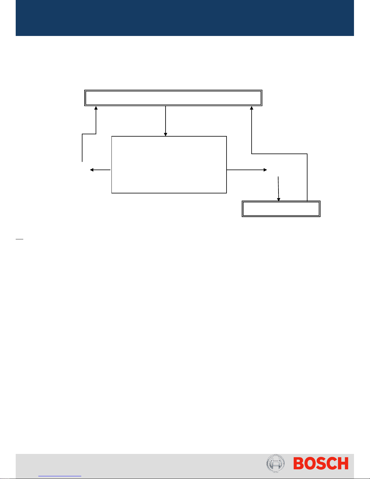
HP Heating Water
T bot < 25ºC
&
Check Tapping Process
(T top - Tbot < 8ºC
&
T set – Ttop < 5ºC for 5 min)
False
True
HP stops for 1 h
Page 6 from 56 6-720-821-364 SM HP270 – 250 - 200 2016/12 en
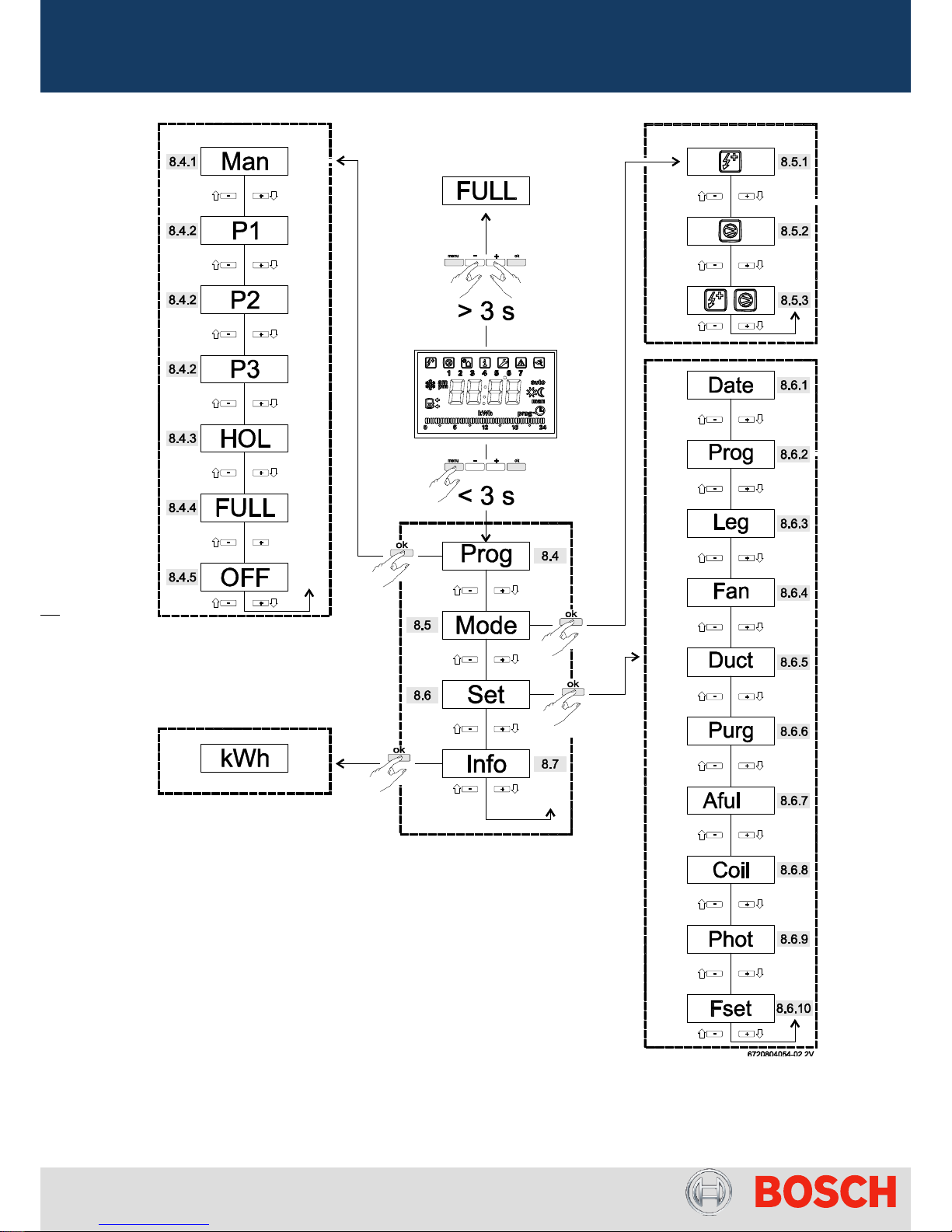
Pict.2 – Parameters overview in main and sub menu of HP270-2
Page 7 from 56 6-720-821-364 SM HP270 – 250 - 200 2016/12 en
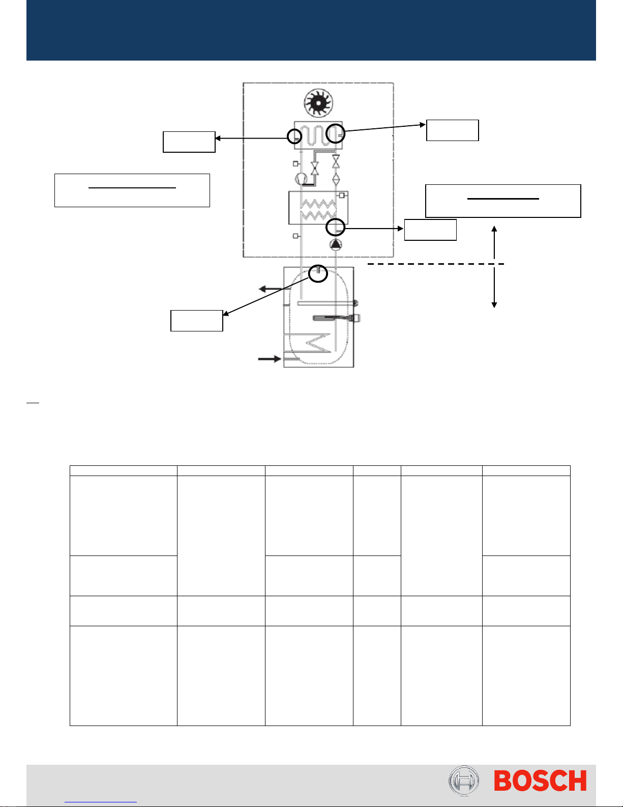
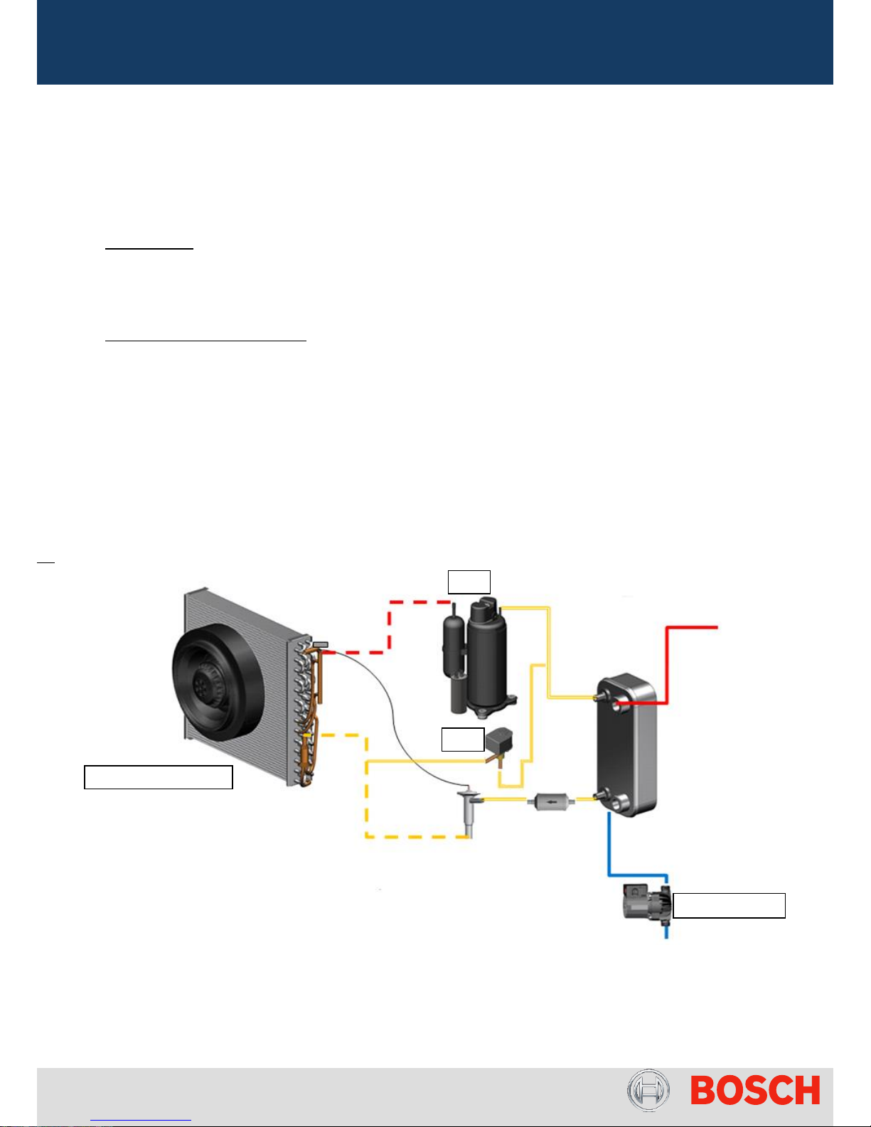
Pict.3 – Heat Pump Diagram (Model HP270-2: -10ºC / +35ºC)
Operation Modes
Applicable to HP-2 with software version:
HPAF0501 / 0502 / 0503 (-10ºC / + 35ºC models)
HPAF0701 / 0702 / 0703 (+5ºC / +35ºC models)
Operation Mode
Evaporator
Compressor
Solenoid
Pump
E-Heater
Combi Mode
Conditions (Man / Aut)
ON if compressor is
ON
Note: If Duct On
starts 2 min before
compressor and if
Duct Off starts 1
min before
compressor in order
to update air
temperature value
ON if -10ºC < T
air
<
+35ºC
and T
bot
< 55ºC
and T
top
< 60ºC
OFF
ON if compressor
is ON or
1 min ON
everyday if
compressor is
OFF
ON if compressor
cannot work due air
temperature
conditions
(T
air
< -10ºC or T
air
>
35ºC)
or Tbot > 55ºC or T
top > 60ºC
Heat Pump Mode
Conditions (Man / Aut)
ON if -10ºC < T
air
<
+35ºC
and T
bot
< 60ºC
OFF
OFF
Electric Heater Mode
Conditions (Man / Aut)
OFF
OFF
OFF
1 min ON every
hour
ON
Full Mode Conditions
ON if compressor is
ON:
Note: If Duct On
starts 2 min before
compressor and if
Duct Off starts 1
min before
compressor in order
to update air
temperature value
ON if -10ºC < T
air
<
+35ºC
and T
bot
< 55ºC
and T
top
< 60ºC
OFF
ON if compressor
is ON or
1 min ON every
hour if E-heater
ON when
compressor is
OFF
ON
Table 2 – Operation Modes Conditions
T
top
T
bottom
T
air
T
fins
Start Up Condition:
T
top
< (T
set
– 3ºC)
Stop Condition:
T
top
≥ T
set
module
tank
Page 8 from 56 6-720-821-364 SM HP270 – 250 - 200 2016/12 en
From FD ≥ 660 (Dec 2016):
HPAF2501 (-10ºC / + 35ºC models) (HP270-3)
HPAF2701 (+5ºC / +35ºC models) (HP270-3)
Introduction of HP 270-3 Model
Product Changes:
- New HMI concept;
- Remove of “Rcir” parameter;
- Replacement of Tank Bushes;
- Replacement of charging / measurement point cover;
- Magnesium Anode in tank bottom but possible control by measuring current;
- Electric heater integration in module;
- Change of pump: Electronically controlled with variable speed;
- Change of Fan: Electronically controlled;
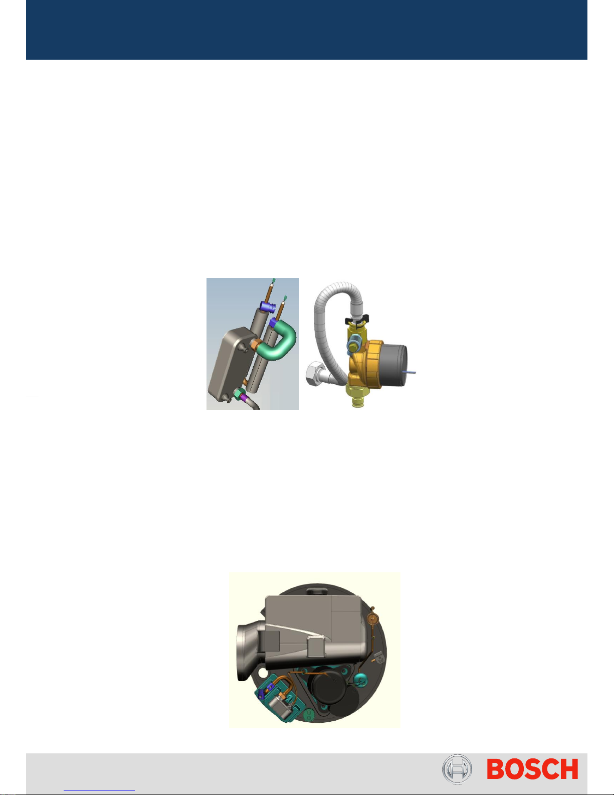
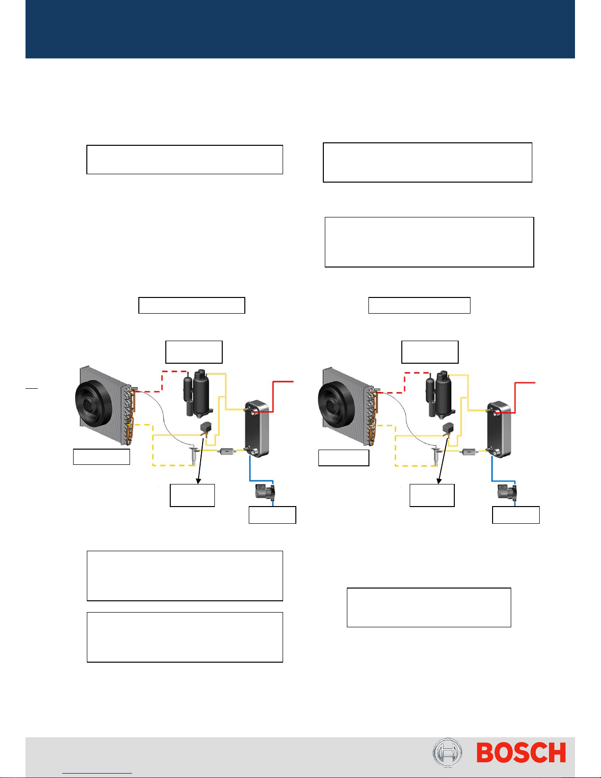
Pict. 4 – Detail of impact in hydraulic circuit with electric heater in top of module and new pump
From FD ≥ 660 (Dec 2016):
HPAF2801 (+5ºC / +35ºC models) (HP200/250-1)
Introduction of HP 200/250-1 Platform
Product Changes:
- New Tank Platform (200 / 250 litres)
- New Module design with side connections for air
- Electric heater integrated in module
- Anode in top of tank
Pict. 5 – Detail of new module platform in HP200/250-1

Page 9 from 56 6-720-821-364 SM HP270 – 250 - 200 2016/12 en
Pict.5 – Parameters overview in main and sub menu of HP270-3 / HP200/250-1
Applicable to HP-3 with software version:
HPAF2501 (-10ºC / + 35ºC models) (HP270-3)
HPAF2701 (+5ºC / +35ºC models) (HP270-3)
HPAF2801 (+5ºC / +35ºC models) (HP200/250-1)
Operation Mode
Evaporator
Compressor
Solenoid
Pump
E-Heater
Combi Mode
Conditions (Man /
Aut)
ON if compressor is
ON
Note: If Duct On
starts 2 min before
compressor and if
Duct Off starts 1 min
before compressor in
order to update air
temperature value
ON if -10ºC <
T
air
< +35ºC
and T
dis
< 61ºC
and T
top
< 58ºC
(same for +5ºC
model)
OFF
ON if
compressor is
ON
or
ON
if E-heater ON
when
compressor is
OFF
ON if compressor
cannot work due air
temperature
conditions
(T
air
< -10ºC or T
air
> 35ºC)
or T
dis
> 63ºC or T
top
> 60ºC
Economic Mode
Conditions (Man /
Aut)
ON if -10ºC <
T
air
< +35ºC
and T
top
< 60ºC
OFF
ON if T
air
< -10ºC
Or
T
air
> 35ºC
(same for +5ºC
model)
Electric Heater
Mode Conditions
(Man / Aut)
OFF
OFF
OFF
ON
ON
Page 10 from 56 6-720-821-364 SM HP270 – 250 - 200 2016/12 en
Boost Mode
Conditions
ON if compressor is
ON:
Note: If Duct On
starts 2 min before
compressor and if
Duct Off starts 1 min
before compressor in
order to update air
temperature value
ON if -10ºC <
T
air
< +35ºC
and T
dis
< 61ºC
and T
top
< 58ºC
OFF
ON if
compressor is
ON
or
ON if E-heater
ON when
compressor is
OFF
ON
Table 3 – Operation Modes Conditions
2.2) Protection Modes
Anti-Freeze Protection
The anti freeze protection is designed to protect both the module and the tank and is active in all conditions,
specially, when the appliance is set in Heat Pump, standby, OFF and Holyday (Hol) modes.
Note: In order to ensure the anti freeze protection activation, the mains plug must not be disconnected.
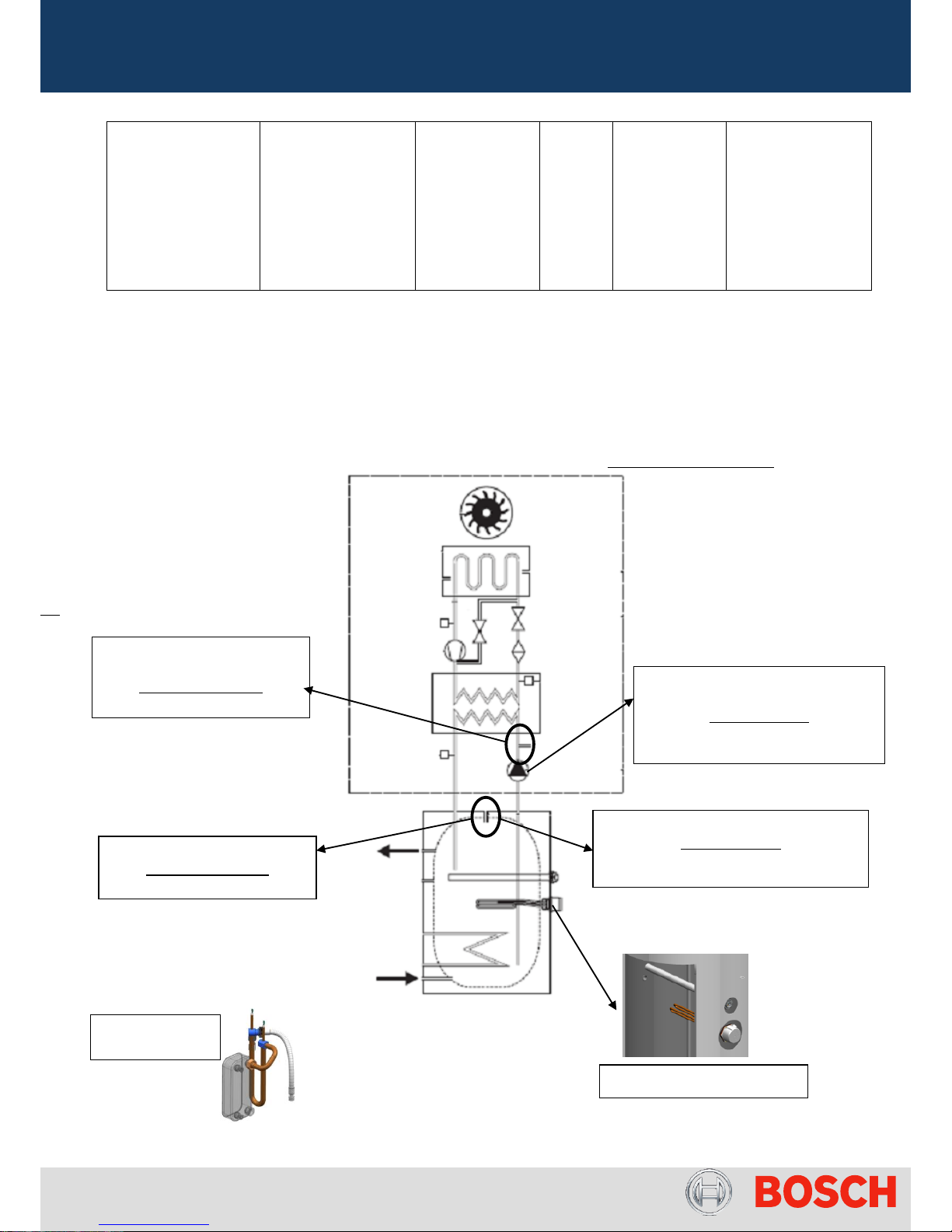
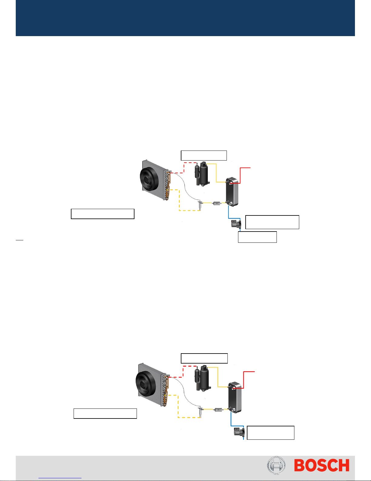
Pict.6 – Heat Pump Diagram (Model HP270-2: -10ºC / +35ºC)
Module Protection
Start Up Condition:
T
Bottom
< 4ºC
Module Protection
Stop Condition:
Until T
bottom
> 6ºC + Water Pump
ON during 1 min
Tank Protection
Start Up Condition:
T
top
< 5ºC
Tank Protection
Stop Condition:
E-Heater ON until T
top
> 8ºC
(not in case of Full or Legionela activation)
Pump + Electric Heater ON
Pump + Electric
Heater ON
Only HP270-3 and HP200/250-1:
Integrated E-Heater in module
Page 11 from 56 6-720-821-364 SM HP270 – 250 - 200 2016/12 en
Legionela disinfection:
From both manual (instantaneous) and automatic (weekly operation) selection, the legionela function will assure
the COMBI mode operation during the 1st 24 hours (compressor until T
top
> 60ºC and only E-Heater until T
top
>
70ºC), nevertheless and if this was not enough to complete LEG function, the HP switch to FULL mode.
Stop condition:
T
top
> 70ºC or T
bottom
> 60ºC or Leg function time > 48h (24 hours in combi and 24 hours in FULL)
Stop condition (only for HP270-3):
T
discharge
> 60ºC during 10 min or Leg function time > 48h (24 hours in combi and 24 hours in BOOST)
Conditions for air-defrost sequence:
Air defrost sequence is activated in both +5ºC / +35ºC and -10ºC / +35ºC models when 5ºC < T
air
< 10ºC for more
than 60 min and compressor is ON for more than 60 min as well with recurrence determined by the temperature
measured by T
bottom
sensor.
Pict.7 – Status diagram for air defrost
Condition HPAF0501/0701:
T
bottom
< 20ºC
(defrost every 90 min)
T
bottom
< 35ºC
(defrost every 360 min)
T
bottom
< 60ºC
(defrost every 840 min)
OFF
ON during 10 min
Water Pump OFF
OFF
Condition
HPAF0502/0702
HPAF0503/0703
T
bottom
< 20ºC
Or
Tair-Tfins > 6ºC
(defrost every 90 min)
Condition
HPAF2501/2701
HPAF2801
T
discharge
< 20ºC
Or
Tair-Tfins > 6ºC
(defrost every 90 min)
Page 12 from 56 6-720-821-364 SM HP270 – 250 - 200 2016/12 en
o Changes in Air Defrost sequence
(Attention: only +5ºC / +35ºC model)
Current Behaviour:
Air defrost sequence is activated when 5ºC < T
air
< 10ºC for more than 60 min and compressor is ON for more than
60 min. the nº of cycles depends on detection of following additional conditions.
Condition (HPAF0702 / HPAF0703):
T
bottom
< 20ºC
Or
T
air
- T
fins
> 6ºC
(defrost every 90 min)
Pict.8 – Air Defrost Sequence
New Behaviour (only in HPAF0703):
In addition to current function in +5ºC / +35ºC models an additional air defrost sequence is programmed. When 0ºC
< T
air
(3d) < + 5ºC will last for more than 60 min and compressor is ON for more than 60 min, the evaporator defrost
will start. The fan will run during 45 min to defrost evaporator and in the meanwhile the electric heater will heat up
the water.
Condition (HPAF0703 + 1701 + 2701):
Compressor is ON for more than 60 min and
T
air -Tfins
> 3.5ºC for more than 1 min or T fins < -17ºC
Pict.9 – Air Defrost Sequence
Fan ON during 10 min
T
bottom
Water Pump OFF
Compressor OFF
Fan ON during 45 min
Water Pump OFF
Compressor OFF
Page 13 from 56 6-720-821-364 SM HP270 – 250 - 200 2016/12 en
Conditions for gas-defrost sequence:
Gas Defrost sequence is activated only in -10ºC / +35ºC models when -10ºC < T
air
< 5ºC for more than 60 min,
performed in 2 steps (Pre-gas defrost + Gas defrost), according to the compressor operation conditions.
Or
or
Pict.10 – Status diagram for gas defrost procedure
1st step: Pre-Gas Defrost
2nd step: Gas Defrost
Fan ON
Fan OFF
Solenoid
ON
Compressor
ON
Compressor
ON
Time for pre-gas defrost (HP270-2):
T
bottom
< 25ºC / Time = 2 min
T
bottom
> 25ºC and < 40ºC / Time = 1 min
T
bottom
> 40ºC / Time = 0.5 min
Gas Defrost sequence stops when
T
fins
> 6ºC or gas defrost lasts for
more than 30 min
Condition 1:
Compressor is ON for more than 180 min
Condition 2.1:
Compressor is ON for more than 60 min and
T
air -Tfins
> 3.5ºC for more than 1 min
Solenoid
OFF
Condition 2.2:
Compressor is ON for more than 60 min and
T fins < -17ºC or compressor stopped for some
reason
OFF
OFF
Time for pre-gas defrost (HP270-3):
T
discharge
< 25ºC / Time = 2 min
T
discharge
> 25ºC and < 40ºC / Time = 1 min
T
discharge
> 40ºC / Time = 0.5 min
Page 14 from 56 6-720-821-364 SM HP270 – 250 - 200 2016/12 en
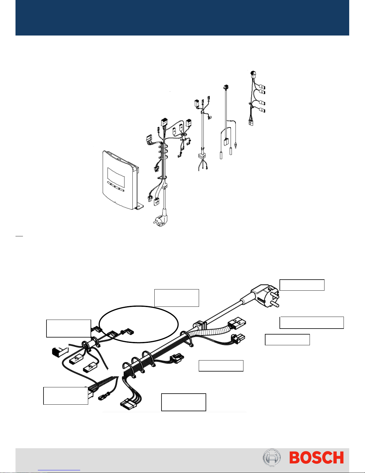
3) Electric Measurements
Pict.11 – Control Unit and cables overview
Main Cable supply
Pict.12 – Mains Power Supply
Mains Plug
Solenoid
Water Pump
High Pressure Switch
PCB: AC
Connector
PCB
Connector
Compressor
Connections
Capacitor
Connection
Brown -
Blue
Brown -
Blue
Grey-Grey
White
Blue
Black
Grey
Black
Page 15 from 56 6-720-821-364 SM HP270 – 250 - 200 2016/12 en
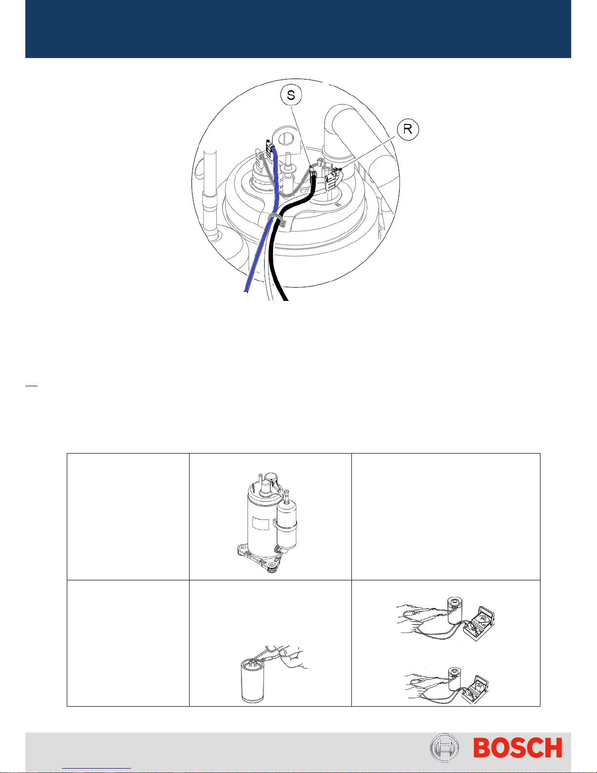
Pict.13 – Compressor Connection Detail
Compressor
- After turn ON the appliance, the compressor should operate for more than 5 minutes.
- The compressor should be operated for more than 20 seconds within 15 minutes after charging refrigerant
into the system to ensure proper lubrication
- The compressor should never be operated while under vacuum, otherwise, internal arcing can damage
some parts.
- The compressor should not be left opened in the atmosphere for more than 5 minutes.
Highly
(model WHP01900BSV)
Specification from supplier:
- Standard condition: 1.9 kW of heating
capacity / 475 W input
- Thermal protection included
(temperature limiter: opens at 160ºC,
closes at 70ºC)
- 270 ml of oil capacity
Capacitor (15 µF)
In case of check capacitor, discharge
electric charge with a resistance of
20kΩ
OK – scale decrease to 0 and pass to ∞
Not OK – 0Ω
Page 16 from 56 6-720-821-364 SM HP270 – 250 - 200 2016/12 en
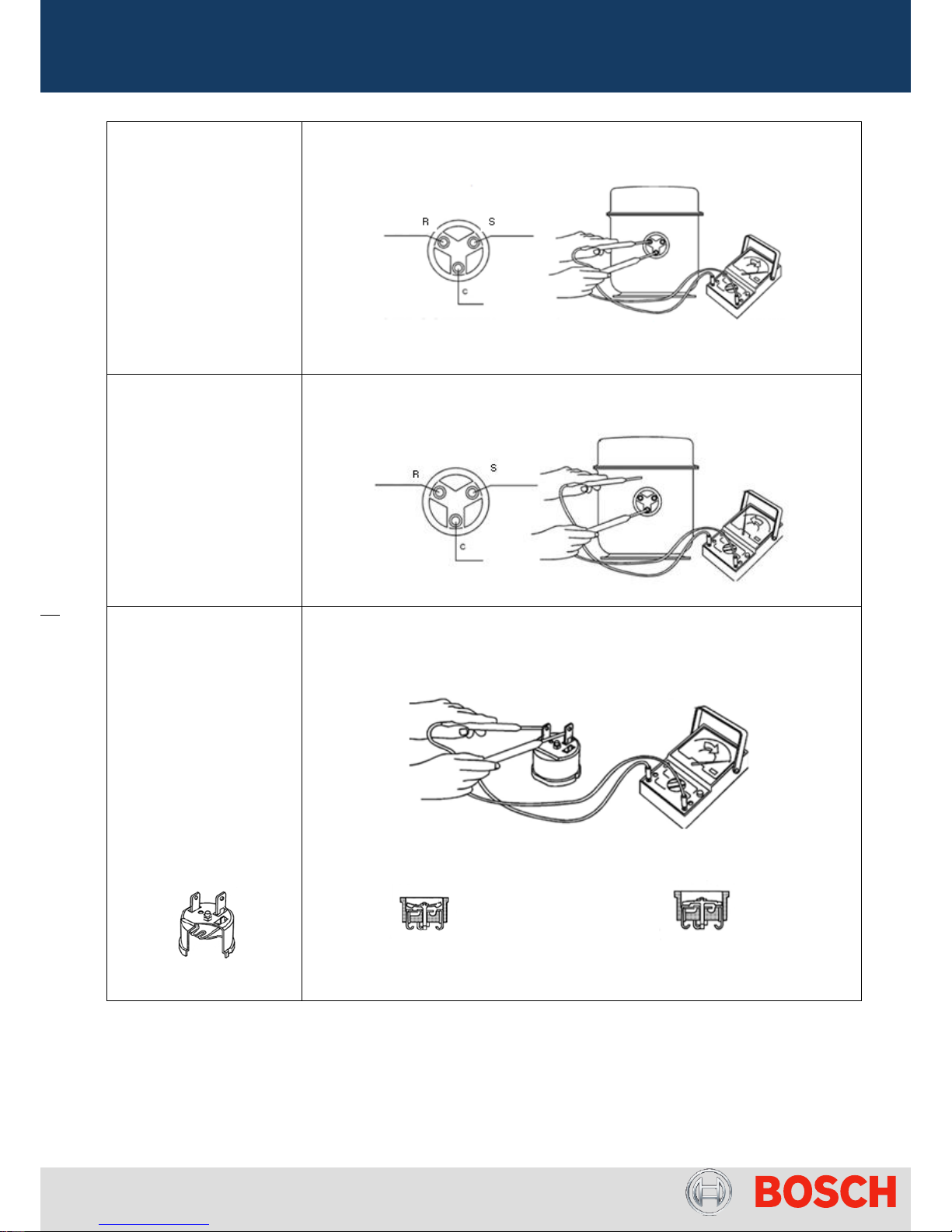
Between C – R > 0
Highly ≈ 5.84 Ω
Between C – S > 0
Highly ≈ 7.62 Ω
Between R – S > 12 Ω
(values @ 20ºC)
Checking Continuity and Resistance (Ω):
Check earth connection
C – chassis ≠ 0
S – chassis ≠ 0
R – chassis ≠ 0
Attention: In case of
continuity the compressor
is defected
Electric test to compressor:
Thermal Protection
This function is ensured by
a bimetallic temperature
limiter which opens its
contact when high
temperature (T=160ºC
±10ºC) is reached during
operation.
Testing of thermal protection limiter:
Open contact Close contact
temperature activation – T≥160ºC normal operation – T<70ºC
Table 4 – Compressor components overview
Page 17 from 56 6-720-821-364 SM HP270 – 250 - 200 2016/12 en
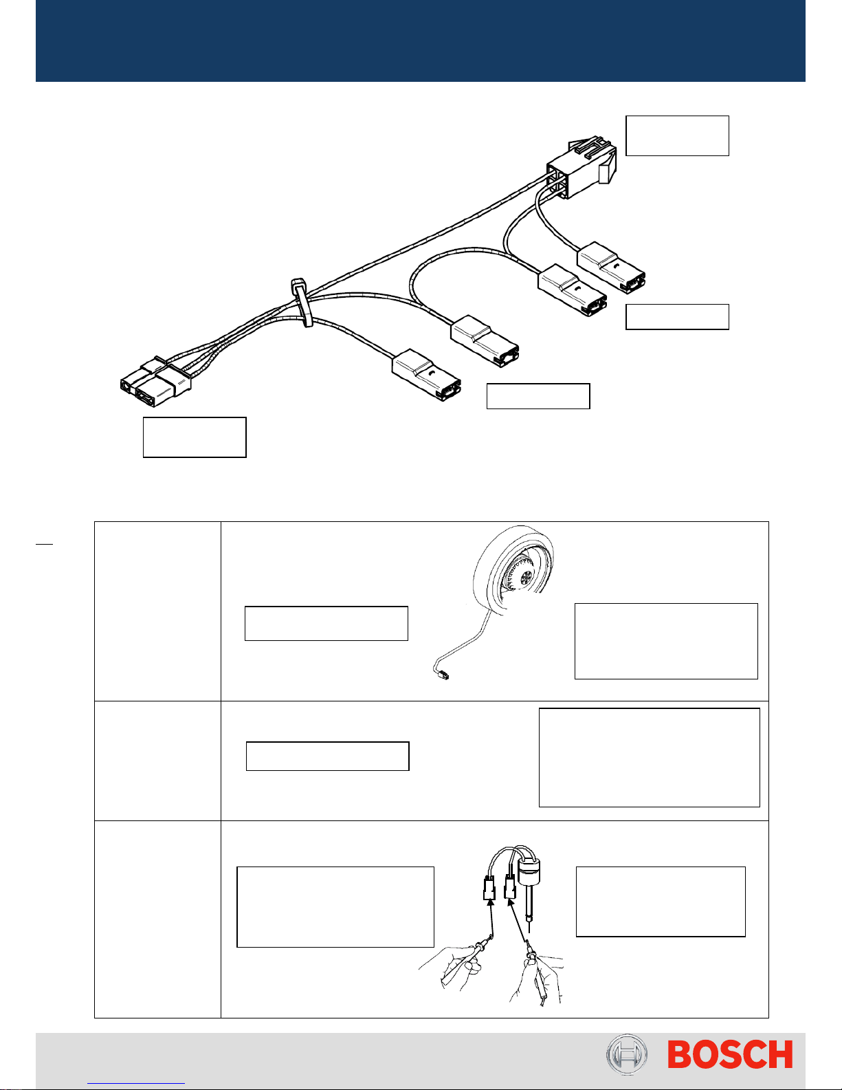
Capacitor / Fan Cable
Pict.14 – Fan Connection (HP270-2)
Fan
(EBM Papst)
AC controlled
Note: Only
HP270-2 and
HP200-250-1
Fan
EC: electronically
controlled
Note:
only HP270-3
High Pressure
Switch connection
(use of multimeter:
continuity or
resistance
measurement)
PCB
Connector
Capacitor 2
Capacitor 1
Fan
Connector
Brown
Brown
Brown
Black
Blue
Contact Normally Closed
Not OK - ∞ (contact opened)
OK - 0Ω (contact closed)
230 V ac between L / N
Note: Continuity Test
performed at atmospheric
pressure or when
component is stopped
HP 270-2
Controlled by 2 capacitors
Start = 2µF
Speed Control = 6.3 µF
230 V ac between L / N
Input Voltage is fix
Variable speed using PWM signal
White: Feedback of speed
Red: Not used
Yellow: PWM Signal
Blue: Ground
 Loading...