


 Loading...
Photobeam 5000
ISC-FPB1-W60QF, ISC-FPB1-W120QF, ISC-FPB1-W200QF
en Installation and Operation Guide

Photobeam 5000 Table of Contents | en 3
Table of contents
1 |
Introduction |
4 |
1.1 |
About documentation |
4 |
1.2 |
Bosch Security Systems, Inc |
4 |
2 |
|
|
System overview |
5 |
|
2.1 |
Features |
5 |
2.2 |
Photobeam overview |
6 |
2.3 |
Console overview |
7 |
2.4 |
Transmitter/receiver dimensions |
8 |
3 |
|
|
Installation |
9 |
|
3.1 |
Beam spread |
9 |
3.2 |
Pole mount installation |
10 |
3.3 |
Wall mount installation |
12 |
4 |
|
|
Wiring |
13 |
|
4.1 |
Terminal strip overview |
13 |
4.2 |
Wiring distance |
14 |
4.3 |
Wiring routes |
14 |
5 |
|
|
Special features |
16 |
|
5.1 |
Selectable beams |
16 |
5.2 |
Selectable AND/OR Gate |
16 |
5.3 |
Level LED |
16 |
5.4 |
EDC (Environmental Discrimination Circuit) |
16 |
5.5 |
Beam interruption time |
17 |
5.6 |
Beam power control |
17 |
5.7 |
High Density |
18 |
6 |
|
|
Setup |
21 |
|
7 |
|
|
Installing multiple sets (stacking) |
25 |
|
7.1 |
Group selection |
25 |
7.2 |
Channel selection |
27 |
7.3 |
Synchro wiring |
29 |
7.4 |
Stacking examples |
30 |
7.4.1 |
Single stacking |
30 |
7.4.2 |
Double stack |
30 |
7.4.3 |
Triple stack |
31 |
7.4.4 |
Quadruple stack |
32 |
8 |
|
|
Optical alignment |
35 |
|
8.1 |
Level LED – alignment of the Upper Beam |
35 |
8.2 |
Level LED - alignment of the Lower Beam |
35 |
8.3 |
Volt meter alignment |
36 |
9 |
|
|
Operational check |
38 |
|
10 |
|
|
Troubleshooting |
39 |
|
10.1 |
Additional information |
39 |
11 |
|
|
Certifications |
40 |
|
12 |
|
|
Specifications |
41 |
Bosch Security Systems, Inc. |
Installation and Operation Guide |
2015.01 | 02 | F.01U.303.478 |

4 en | Introduction Photobeam 5000
1 |
Introduction |
|
This document contains information that a trained installer needs to install the Photobeam |
|
5000 quad-beam photoelectric detector contained inside the packaging. |
1.1 |
About documentation |
|
Copyright |
|
This document is the intellectual property of Bosch Security Systems, Inc. and is protected by |
|
copyright. All rights reserved. |
|
Trademarks |
|
All hardware and software product names used in this document are likely to be registered |
|
trademarks and must be treated accordingly. |
1.2 |
Bosch Security Systems, Inc |
|
Use the serial number located on the product label and refer to the Bosch Security Systems, |
Inc. website at http://www.boschsecurity.com/datecodes/.
Manufacturing date information is contained in digit no 1 – 3: DDD.
2015.01 | 02 | F.01U.303.478 |
Installation and Operation Guide |
Bosch Security Systems, Inc. |

Photobeam 5000 System overview | en 5
2 System overview
The ISC-FPB1-W60QF, ISC-FPB1-W120QF, and ISC-FPB1-W200QF are quad-beam photoelectric detectors designed for indoor and outdoor applications. Consisting of a separate transmitter and receiver, an alarm is activated when a person passes through the beams. Combination of features and adjustable parameters allow for better catch performance, lower false alarm rates, and reduced effects of environmental disturbances.
2.1 Features
For stable operation, the detectors are equipped with the following feautres:
100% Sensitivity Allowance
Maintains stable operation even if 99% of beam energy is cut, for example by rain, fog, frost, and so on.
Quad Beam Detection
Fewer false alarms caused by birds and other small animals because all four beams must be blocked simultaneously to cause an alarm.
Beam Power Control
Select the appropriate beam intensity relative to the detection range to minimize reflection on nearby walls and cross-talk with other detectors.
Beam Interruption Time Control
Use to change the beam interruption time to best fit the application.
Bosch Security Systems, Inc. |
Installation and Operation Guide |
2015.01 | 02 | F.01U.303.478 |
6 en | System overview Photobeam 5000
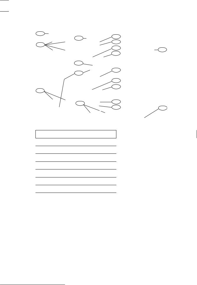
2.2 |
Photobeam overview |
|
|
|
|
|
2 |
|
|
|
|
6 |
7 |
|
|
|
|
|
|
|
|
|
8 |
|
|
|
1 |
|
|
|
|
|
9 |
12 |
|
|
|
|
|
|
|
|
10 |
|
|
|
5 |
|
|
|
|
|
11 |
|
|
|
4 |
|
|
|
|
|
10 |
|
|
|
|
9 |
|
|
|
1 |
|
|
|
|
3 |
8 |
|
|
|
|
|
|
|
|
|
7 |
13 |
|
Figure 2.1: Photobeam components overview |
|
|
|
|
Callout Description |
|
Callout Description |
|
|
1 |
Mounting holes |
|
8 Optical alignment |
|
2 |
Mounting plate |
|
9 Vertical adjustment |
|
3 |
Device securing screws |
|
10 Horizontal adjustment |
|
4 |
Wire entry |
|
11 Console |
|
5 |
Wiring terminals |
|
12 Cover |
|
6 |
Detector |
|
13 Cover securing screws |
|
7 |
Optical module |
|
|
2015.01 | 02 | F.01U.303.478 |
Installation and Operation Guide |
Bosch Security Systems, Inc. |
Photobeam 5000 System overview | en 7
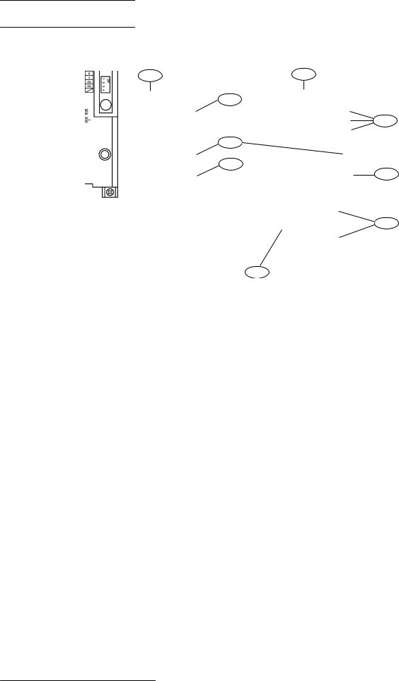
2.3 Console overview
5
2
6
3
4
7
8
9
Figure 2.2: Console components overview
Callout Description |
Callout Description |
||
|
|
|
|
1 |
Transmitter console |
6 |
Status indicators |
|
|
|
|
2 |
Power indicator |
7 |
Sensitivity control |
|
|
|
|
3 |
Function switches |
8 |
ALIGNMENT CHECK TERMINALS |
|
|
|
|
4 |
BEAM POWER CONTROL |
9 |
HIGH DENSITY terminals |
|
|
|
|
5 |
Receiver console |
|
|
|
|
|
|
Bosch Security Systems, Inc. |
Installation and Operation Guide |
2015.01 | 02 | F.01U.303.478 |

8 en | System overview Photobeam 5000
2.4 |
Transmitter/receiver dimensions |
|
|
103 MM (4.0 IN) |
96 MM (3.77 IN) |
|
77.1 MM |
(3.03 IN) |
3 |
|
) |
|
244 MM (9.60 IN) |
IN |
398 MM (15.66 IN) |
337.7 MM (13.29 |
4
1
19.3 |
MM |
2 |
|
||
(0.75 IN) |
|
|
Figure 2.3: Transmitter/receiver dimensions
56 MM
(2.20 IN)
39.7 MM |
(1.56 IN) |
39 MM |
(1.5 IN) |
220 MM (8.66 IN)
Callout Description |
Callout Description |
||
|
|
|
|
1 |
Knockout wire entrance |
3 |
Center of the Upper Beam |
|
|
|
|
2 |
Center of the Lower Beam |
4 |
Wire entrance |
|
|
|
|
2015.01 | 02 | F.01U.303.478 |
Installation and Operation Guide |
Bosch Security Systems, Inc. |

Photobeam 5000 |
Installation | en |
9 |
|
|
|
3 Installation
Prior to installing the devices, please review the installation considerations below:
–Install in an area that is clear of objects
–Install the transmitter/receiver within the maximum protection range of the model
–Do not install:
–Receivers into intense sources of light (for example, rising and setting sun)
–On movable surfaces subject to vibrations
–Detectors where immersion to water, corrosive liquids, or exposure to high levels of dust can occur
–Detectors in close proximity to strong electromagnetic noises
–Do not use detectors with other photobeam detectors or receivers
–Do not disassemble or modify this detector
–Do not install while the power is on
–Avoid extreme temperature and humidity ranges as defined in the products specifications
–Avoid installing detectors near magnets and/or magnetized materials
–Avoid beam interference between other units when multiple units are installed
–Use the selectable beam’s feature when stacking detectors
3.1 Beam spread
The beam spread angle is ±0.7 °from the transmitter to the receiver. Refer to the diagram and table below to determine the installation conditions.
2
3
1
4
5
Figure 3.1: Beam distance and spread
Callout Description |
Callout Description |
||
|
|
|
|
1 |
Transmitter |
4 |
Receiver |
|
|
|
|
2 |
Horizontal spread (B) |
5 |
Distance (A) |
|
|
|
|
3 |
Vertical spread (C) |
|
|
|
|
|
|
Bosch Security Systems, Inc. |
Installation and Operation Guide |
2015.01 | 02 | F.01U.303.478 |
10 en | Installation Photobeam 5000
|
Distance, horizontal and vertical spread values: (A) / (B) / (C) |
|
|
|
|
|
Metric |
Imperial unit |
|
|
|
|
20 m / 0.5 m / 0.8 m |
65 ft / 1.6 ft / 2.6 ft |
|
|
|
|
40 m / 1.0 m /1.3 m |
13.1 ft / 3.2 ft / 4.2 ft |
|
|
|
|
60 m / 1.5m / 1.8 m |
196 ft / 4.9 ft / 5.9 ft |
|
|
|
|
80 m / 2.0 m / 2.2 m |
262 ft / 6.5 ft / 7.2 ft |
|
|
|
|
100 m / 2.5 m / 2.7 m |
328 ft / 8.2 ft / 8.8 ft |
|
|
|
|
120 m / 3.0 m / 3.2 m |
393 ft / 9.8 ft / 10.4 ft |
|
|
|
|
140 m / 3.5 m / 3.7 m |
459 ft / 11.4 ft / 12.1 ft |
|
|
|
|
160 m / 4.0 m / 4.2 m |
524 ft / 13.1 ft / 13.7 ft |
|
|
|
|
180 m / 4.5 m / 4.7 m |
590 ft / 14.7 ft / 15.4 ft |
|
|
|
|
200 m / 5.0 m / 5.2 m |
656 ft / 16.4 ft / 17.0 ft |
|
|
|
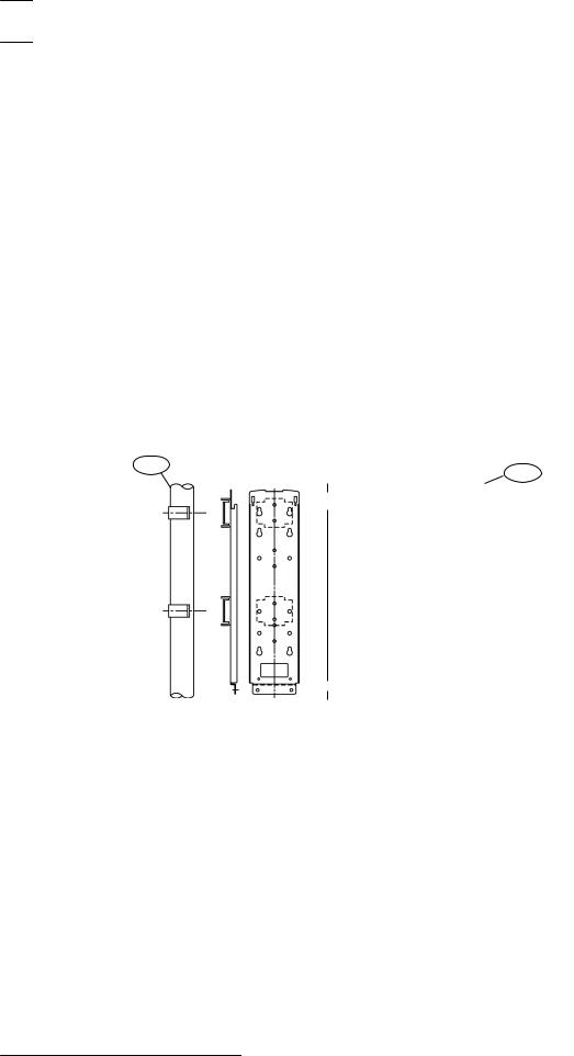
3.2 |
Pole mount installation |
|
|
1 |
2 |
|
|
|
Figure 3.2: Pole mounting view
Callout Description |
Callout Description |
|
|
1 Diameter 38.0 – 42.7 mm (1.50 – 1.68 |
2 Back-to-back pole mounting |
in) |
|
|
|
Attaching the mounting bracket:
1.Choose an appropriate mounting location for the devices. Install the mounting poles with a clear line-of-sight between the transmitter and receiver.
2.Loosen the transmitter’s cover mounting screw and remove the cover.
3.Loosen the two base mounting screws and remove the mounting plate by sliding it down.
4.Attach the mounting hardware to the mounting plate using the clamping screws. Refer to the figure below.
2015.01 | 02 | F.01U.303.478 |
Installation and Operation Guide |
Bosch Security Systems, Inc. |
Photobeam 5000 Installation | en 11
1 |
2 |
|
3
Figure 3.3: Attaching the mounting bracket
Callout Description
1 Mounting hardware
2 Mounting plate
3 Clamping screws (short)
Attaching the mounting plate:
1.Attach the mounting plate to the poles using the U-clamps.
2.Use the U-clamps and clamping screws to attach the mounting plate firmly to the poles.
2
3
1
4
Figure 3.4: Attaching the U-clamp
Callout Description
1 U-clamp
2 Mounting pole
3 Mounting plate
4 Clamping screws (long)
Wire routing:
1.Route the wire through the wire entry location of the mounting plate, leave enough wire to reach the terminal strip.
2.Route the wire through the transmitter’s wire entry.
3.Slide the transmitter onto the mounting plate, and secure using the included screws.
4.Repeat this procedure for the receiver, verify line-of-sight with the transmitter.
5.Wire to the terminal strips. Refer to Wiring for wiring procedures.
Bosch Security Systems, Inc. |
Installation and Operation Guide |
2015.01 | 02 | F.01U.303.478 |
12 en | Installation |
Photobeam 5000 |
|
|
|
|
Caution!
!Ensure that the pole mount installation is secure and stable. Failure to do so may result in personal injury, or damage the device.
3.3 |
Wall mount installation |
Installing the transmitter and receiver:
1.Remove the cover and mounting plate from the transmitter.
2.Route the wire through the mounting plate wire entry if the wire is routed through a wall opening. If the wire is routed on the wall surface, knock-out the thin wall wire hole at the bottom of the transmitter and cover. Route the wire through the opening after the mounting plate is secured onto the wall.
3.Secure the mounting plate to the wall surface.
4.Route the wire through the detector wire entry location.
5.Secure the transmitter to the mounting plate.
6.Wire to the terminal strips. Refer to Wiring for wiring procedures.
7.Repeat this procedure for mounting the receiver.
2
3
1
6
5
4
Figure 3.5: Wall mount installation
|
Callout Description |
Callout Description |
||
|
|
|
|
|
|
1 |
Mounting screws |
4 |
Device securing screws |
|
|
|
|
|
|
2 |
Mounting plate |
5 |
Knockout |
|
|
|
|
|
|
3 |
Detector |
6 |
Wire entry |
|
|
|
|
|
|
|
|
|
|
2015.01 | 02 | F.01U.303.478 |
Installation and Operation Guide |
Bosch Security Systems, Inc. |

Photobeam 5000 |
Wiring | en 13 |
|
|
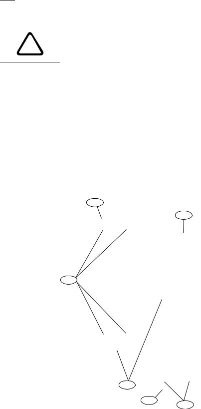
4 Wiring
Refer to Terminal strip below for transmitter/receiver terminal locations. Use duct pipes for outdoor wiring. Do not use aerial wiring.
Caution!
!Complete all electrical connections and inspect them prior to applying power.
Notice!
Tamper and EDC terminals should be connected to a 24-hour supervisory loop
Notice!
Power is to be provided by a UL Listed burglar alarm power supply or burglar alarm control panel. In case of power failure, the power supply or control unit shall have a minimum of 4 hours of standby power.
Notice!
All wiring is to be in accordance with the National Electric Code, ANSI/NFPA 70.
Notice!
This system should be tested at least once a week to ensure proper function.
4.1 |
Terminal strip overview |
|
|
1 |
2 |
|
4 |
6 |
5 |
3 |
|
4 |
3 |
Figure 4.1: Terminal strip component overview |
|
|
|
||||
|
|
|
|||||
Callout Description |
|
Callout Description |
|||||
|
|
|
|
|
|
||
1 |
Receiver |
|
|
4 |
Tamper |
||
|
|
|
|
|
|
||
2 |
Transmitter |
|
|
5 |
Alarm output |
||
|
|
|
|
||||
3 |
Power (non-polarized) |
6 |
EDC output |
||||
|
|
|
|
|
|
|
|
Bosch Security Systems, Inc. |
Installation and Operation Guide |
2015.01 | 02 | F.01U.303.478 |

14 en | Wiring Photobeam 5000
4.2 Wiring distance
Refer to the table to determine the minimum wire gauge for a single sensor system (one transmitter and one receiver). The distances specified are between the power source and the last (farthest) unit on the single wire run. For multiple detector configurations, divide the wire distance in the table by the number of systems in the configuration (1 system = 1 transmitter and 1 receiver).
Wire Gauge |
Maximum wiring distance |
|
|
|
|||
|
|
|
|
|
|
|
|
|
|
ISC-FPB1-W60QF |
ISC-FPB1-W120QF |
ISC-FPB1-W200QF |
|||
|
|
|
|
|
|
|
|
AWG |
Ø mm |
12V |
24V |
12V |
24V |
12V |
24V |
|
|
|
|
|
|
|
|
22 |
0.65 |
90 m |
820 m |
80 m |
790 m |
80 m |
770 m |
|
|
(295 ft) |
(2690 ft) |
(262 ft) |
(2591 ft) |
(262 ft) |
(2526 ft) |
|
|
|
|
|
|
|
|
19 |
0.90 |
170 m |
1600 m |
170 m |
1550 m |
160 m |
1500 m |
|
|
(557 ft) |
(5249 ft) |
(557 ft) |
(5085 ft) |
(524 ft) |
(4921 ft) |
|
|
|
|
|
|
|
|
17 |
1.14 |
320 m |
2930 m |
310 m |
2830 m |
300 m |
2740 m |
|
|
(1049 ft) |
(9612 ft) |
(1017 ft) |
(9284 ft) |
(984 ft) |
(8989 ft) |
|
|
|
|
|
|
|
|
14 |
1.62 |
570 m |
5150 m |
550 m |
4980 m |
530 m |
4820 m |
|
|
(1870 ft) |
(18896 ft) |
(1804 ft) |
(16338 ft) |
(1738 ft) |
(15813 ft) |
|
|
|
|
|
|
|
|
4.3 Wiring routes
Refer to the graphics below for wiring routes examples. The illustrations depict both one, and two sets of detector systems on a single wire run.
The graphics below show simple examples of wiring concepts, depicting how to power the transmitter and receiver pairs, and how to combine alarm outputs. Local regulatory requirements and technical parameters specific to a connected control panel determine the exact details of the wiring. Review local regulations and the connected control panels technical documentation before planning wire routes and connections. Selecting the proper wire routes and gauges depend on the number of devices, overall distance, and voltage drop parameters for each individual device.
2015.01 | 02 | F.01U.303.478 |
Installation and Operation Guide |
Bosch Security Systems, Inc. |
Loading...