


 Loading...
GPRS/GSM IP Communicator
Conettix ITS-DX4020-G
en Installation and Operation Guide

GPRS/GSM IP Communicator |
Table of Contents | en |
3 |
|
|
|
Table of Contents
1 |
Introduction |
5 |
1.1 |
Trademarks |
5 |
1.2 |
Technical Specifications |
5 |
1.3 |
Certifications and Approvals |
6 |
1.4 |
Control Panel Compatibility |
6 |
2 |
Overview |
7 |
2.1 |
System Overview |
7 |
2.2 |
Device Overview |
8 |
2.3 |
Modes of Operation |
9 |
2.4 |
Configuration Options |
10 |
3 |
Installation |
11 |
3.1 |
Installation Prerequisites |
11 |
3.2 |
Insert the SIM Card |
12 |
3.3 |
Mount the ITS-DX4020-G in the Control Panel Enclosure |
13 |
3.4 |
Connect the ITS-DX4020-G to the Control Panel |
14 |
3.5 |
Check Signal Strength |
17 |
4 |
Configuration |
18 |
4.1 |
Use Short Message Service (SMS) to Configure the ITS-DX4020-G |
18 |
4.1.1 |
Enter CONFIG MODE |
18 |
4.1.2 |
Compose the Configuration SMS |
19 |
4.1.3 |
Send the Configuration SMS |
20 |
4.1.4 |
Exit from CONFIG MODE |
21 |
4.2 |
Use USB to Configure the ITS-DX4020-G |
21 |
4.2.1 |
Install the USB Driver |
22 |
4.2.2 |
Install a Communication Program |
24 |
4.2.3 |
Log Into the USB Interface |
25 |
4.2.4 |
USB Main Menu |
27 |
4.2.5 |
USB Option Menu |
27 |
4.3 |
Polling Configurations |
31 |
4.3.1 |
High Security Application (bank, jewelry store, UL fire, and so on) |
31 |
4.3.2 |
Medium Security Application |
32 |
4.3.3 |
Backup or Low Security Application (residential or other once-a-day reporting location) |
33 |
4.4 |
SIM Card Data Usage |
34 |
5 |
Testing |
35 |
5.1 |
GSM Trouble Indication |
35 |
5.2 |
Firmware Version |
35 |
|
|
|
6 |
Firmware Upgrade |
36 |
6.1 |
Download the Latest Firmware |
36 |
6.2 |
Install the Firmware |
36 |
6.2.1 |
Install the Firmware using Hyper Terminal |
36 |
Bosch Security Systems, Inc. |
Installation and Operation Guide |
F01U133268 | 03 | 2010.05 |

4 en | Table of Contents GPRS/GSM IP Communicator
6.2.2 |
Install the Firmware using Tera Term |
38 |
|
|
|
7 |
Troubleshooting |
41 |
7.1 |
Diagnostic LED Descriptions |
41 |
7.2 |
Troubleshooting Procedures |
45 |
7.2.1 |
The ITS-DX4020-G does not power on (no LEDs are lit). |
45 |
7.2.2 |
Initialization |
45 |
7.2.3 |
Hardware |
45 |
7.2.4 |
Firmware |
45 |
7.2.5 |
Radio Registration |
46 |
7.2.6 |
SIM Card |
46 |
7.2.7 |
PIN Code |
46 |
7.2.8 |
Control Panel Bus |
47 |
7.2.9 |
No Authorization |
47 |
7.2.10 |
Invalid Configuration SMS |
47 |
7.2.11 |
Firmware Upgrade In Process |
48 |
7.2.12 |
No Incoming IP Packets |
48 |
7.2.13 |
Control Panel Bus Problem |
48 |
7.2.14 |
Radio Initializing or No Signal Strength |
49 |
7.2.15 |
GSM Network Registration |
49 |
7.2.16 |
Unacceptable Signal Strength |
49 |
7.2.17 |
Marginal RF Signal |
50 |
7.2.18 |
Wireless Reception Issues |
50 |
F01U133268 | 03 | 2010.05 |
Installation and Operation Guide |
Bosch Security Systems, Inc. |

GPRS/GSM IP Communicator Introduction | en 5
1 Introduction
1.1 Trademarks
–Microsoft, Windows 2000, XP, Vista, and Windows 7 are either registered trademarks or trademarks of Microsoft Corporation in the United States and/or other countries.
–Molex is a registered trademark of Molex Incorporated.
1.2 |
Technical Specifications |
||
|
|
|
|
Electrical |
|
|
|
|
|
|
|
Current (operating) |
|
– |
Standby: 65 mA |
|
|
– |
Alarm: 200 mA |
|
|
|
|
Operating Voltage |
|
12 VDC nominal |
|
|
|
||
Maximum Wire Resistance for |
1.6 ohms |
||
Control Panel Connections |
|
|
|
|
|
||
Maximum Wire Distance |
– 0.64 mm (22 AWG): 30.5 m (100 ft) |
||
|
|
– 1.02 mm (18 AWG): 61 m (200 ft) |
|
|
|
|
|
Ripple/Noise |
|
200 mVpp maximum |
|
|
|
|
|
PSTN FSX Port |
|
17 V minimum supplied |
|
|
|
|
|
Radio |
|
GSM Quad band radio; 850 MHz and 1900 MHz |
|
|
|
– Europe: 900 MHz and 1800 MHz |
|
|
|
– North America: 850 MHz and 1900 MHz |
|
|
|
|
|
Terminals |
|
All terminals are power-limited. Separate power-limited wiring from non-power- |
|
|
|
limited wiring by 6.4 mm (0.25 in). |
|
|
|
|
|
Environmental |
|
|
|
|
|
|
|
Environment |
|
Indoors |
|
|
|
|
|
Relative Humidity |
|
5% to 93% non-condensing |
|
|
|
||
Temperature (operating) |
-10°C to +55°C (+14°F to +131°F) |
||
|
|
|
|
Mechanical |
|
|
|
|
|
||
Dimensions (H x W x D) |
133 mm x 80 mm x 23 mm (5.2 in. x3.1 in. x 1 in.) |
||
|
|
|
|
Antenna |
|
– Magnetic base omni-directional antenna |
|
|
|
– 2.5 m (8.2 ft) cable with SMA connector |
|
|
|
|
|
SIM Card |
|
3V/1.8V SIM (compliant with GSM 11.12 recommendation) |
|
|
|
|
|
USB |
|
Mini-B connector (cable not included) |
|
|
|
|
|
Accessories |
|
|
|
|
|
||
AE1 Standard Enclosure |
Standard gray enclosure made of 1.0 mm cold-rolled steel. Includes a keyed lock. |
||
|
|
The dimensions are 35.6 cm x 31.8 cm x 7.6 cm (14 in. x 12.5 in. x 3 in.). |
|
|
|
||
AE2 Standard Enclosure |
Standard red enclosure made of 1.0 mm cold-rolled steel. Includes a keyed lock. |
||
|
|
Measures 35.6 cm x 31.8 cm x 7.6 cm (14 in. x 12.5 in. x 3 in.). |
|
|
|
|
|
AE4 Large Enclosure |
|
Large red enclosure made of 1.2 mm coldrolled steel. Includes a keyed lock. |
|
|
|
Measures 52.7 cm x 38.1 cm x 10.8 cm (20.7 in. x 15 in. x 4.25 in.). |
|
|
|
|
|
D2203 Enclosure |
|
Grey steel enclosure measuring 37 cm x 34 cm x 8.9 cm |
|
|
|
(14.6 in. x 13.4 in. x 3.5 in.). Includes a lock and accepts an optional tamper |
|
|
|
switch. |
|
|
|
|
|
Bosch Security Systems, Inc. |
Installation and Operation Guide |
F01U133268 | 03 | 2010.05 |

6 en | Introduction GPRS/GSM IP Communicator
D8103 |
Enclosure |
Grey steel enclosure measuring 41 cm x 41 cm x 9 cm (16 in. x 16 in. x 3.5 in.). |
|
|
|
D8109 |
Fire Enclosure |
Red steel enclosure measuring 40.6 cm x 40.6 cm x 8.9 cm |
|
|
(16 in. x 16 in. x 3.5 in). UL Listed. Includes a lock and key set. |
|
|
|
1.3 |
Certifications and Approvals |
|||
|
|
The ITS-DX4020-G is designed to comply with the following certifications and approvals: |
||
|
|
|
|
|
|
|
Agency |
Certification |
|
|
|
|
|
|
|
|
Australia |
A-Tick Approved |
|
|
|
|
|
|
|
|
CE |
– |
EN60950 Safety |
|
|
|
– |
EN50130-4 Electromagnetic Compatibility |
|
|
|
– |
EN55022 Radiated/Conducted Emissions |
|
|
|
|
|
|
|
FCC |
FCC, Part 15 Radiated/Conducted Emissions |
|
|
|
|
|
|
|
|
NIST |
FIPS 197 Certificate No. |
|
|
|
|
|
|
|
|
PTCRB |
Approved |
|
|
|
|
|
|
|
|
CSFM |
Approved |
|
|
|
|
|
|
|
|
UL |
– UL 365, Police Station Burglar Alarm Units and Systems |
|
|
|
|
– UL 864, UL Commercial Fire Alarm Signaling |
|
|
|
|
– UL 985, Household Fire Warning System Units |
|
|
|
|
– UL 1023 Household Burglar-alarm System Units |
|
|
|
|
– UL 1610, Central Station Burglary |
|
|
|
|
|
|
1.4 |
Control Panel Compatibility |
|||
–DS7200V2 Series (firmware version 2.10 or later)
–DS7400XiV4 (firmware version 4.10 or later)
–FPD-7024 Fire Alarm Control Panel
–Easy Series (firmware version 3.0 or later)
–GV2 Series (firmware version 7.07 or 7.081
–GV3 Series
Refer to your control panel's documentation for programming instructions. When programming the ITS-DX4020-G, follow your control panel’s DX4020 network programming instructions.
F01U133268 | 03 | 2010.05 |
Installation and Operation Guide |
Bosch Security Systems, Inc. |
GPRS/GSM IP Communicator |
Overview | en |
7 |
|
|
|
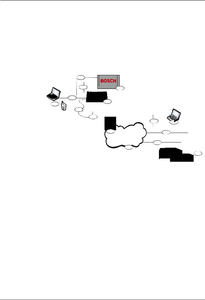
2 Overview
The ITS-DX4020-G enables two-way IP or dialed communication over a commercial GPRS / GSM network. Typical applications are event reporting to a central monitoring station and remote access to Bosch intrusion control panels. For a list of compatible control panels, refer to Section 1.4 Control Panel Compatibility, page 6.
For installations using a PSTN receiver, the ITS-DX4020-G uses GSM to dial the receiver and communicate using Contact ID.
2.1 |
System Overview |
|
|
|
|
|
|
|
|
|
|
|
|||||||||||
|
|
|
|
|
|
|
|
|
|
|
|
|
|
|
|
|
|
|
|
|
|
|
|
|
|
|
|
4 |
|
|
|
|
|
|
|
|
|
|
|
|
|
|
|
|
|||
|
|
|
|
|
|
|
|
|
|
|
|
|
|
|
|
|
|
|
|
||||
|
|
|
|
33 |
|
|
|
|
|
|
|
|
|
|
|
|
|
|
|
||||
|
|
|
|
|
|
2 |
|
|
|
|
|
|
|
|
|
||||||||
|
|
|
|
|
5 |
|
|
|
|
|
|
|
|
|
|
|
|
|
|
|
|||
|
|
|
|
|
|
|
|
|
|
|
|
|
|
|
|
|
|
|
|
|
|
||
|
|
|
|
|
|
|
|
|
|
|
|
|
|
|
|
|
|
|
|
|
|
||
|
|
|
|
|
|
|
|
|
|
|
|
|
|
|
|
|
|
|
|
|
|
||
|
|
|
6 |
|
1 |
|
|
|
|
|
|
|
|
|
|
|
|||||||
|
|
6 |
|
|
|
|
|
|
|
|
|
|
|
|
|
|
|
|
|
|
|
||
|
|
|
|
7 7 |
|
|
|
|
|
|
|
|
|
|
|
|
|
|
|
|
|||
|
|
|
|
88 |
|
|
|
|
|
|
|
|
|
|
|
|
|
||||||
|
|
|
|
|
|
11 |
|
|
|
|
|
||||||||||||
|
|
|
|
|
|
|
|
|
|
|
|
|
|
|
|
|
|
||||||
|
|
|
|
|
|
|
|
|
|
|
|
|
9 |
|
|
|
|
|
13 |
|
|
|
|
|
|
|
|
|
|
|
|
|
|
|
|
|
|
14 |
|
|
|
|
|||||
|
|
|
|
|
|
|
|
|
|
|
|
|
|
|
|
|
|||||||
|
|
|
|
|
|
|
|
|
|
|
|
|
10 |
|
|
|
|
|
|||||
|
|
|
|
|
|
|
|
|
|
|
|
|
|
|
|
|
|
|
|
|
|
||
|
|
|
|
|
|
|
|
|
|
|
|
|
|
|
|
|
|
|
|
|
|
15 |
|
|
|
|
|
|
|
|
|
|
|
|
|
|
|
|
|
|
|
|
|
||||
|
|
|
|
|
|
|
|
|
|
|
|
|
|
|
|
||||||||
|
|
Figure 2.1 |
|
System Overview |
|
|
|
|
|
|
|
|
|
|
|
||||||||
|
|
|
|
|
|
|
|
|
|
|
|
|
|
|
|
|
|
|
|
|
|
|
|
|
|
Callout |
|
|
Description |
|
|
|
|
|
|
|
|
|
|
|
|||||||
|
|
|
|
|
|
|
|
|
|
|
|
|
|
|
|
|
|
|
|
|
|
|
|
|
|
1 |
|
|
|
ITS-DX4020-G GPRS/GSM Communicator |
|
|
|
|
|
||||||||||||
|
|
|
|
|
|
|
|
|
|
|
|
|
|
|
|
|
|
|
|
|
|
|
|
|
|
2 |
|
|
|
Compatible Control Panel |
|
|
|
|
|
|
|
|
|
|
|
||||||
|
|
|
|
|
|
(refer to Section 1.4 Control Panel Compatibility, page 6) |
|
|
|
|
|
||||||||||||
|
|
|
|
|
|
|
|
|
|
|
|
|
|
|
|
|
|
|
|
|
|
|
|
|
|
3 |
|
|
|
Control Panel Dialer Connection (optional) |
|
|
|
|
|
||||||||||||
|
|
|
|
|
|
|
|
|
|
|
|
|
|
|
|
|
|
|
|
|
|
|
|
|
|
4 |
|
|
|
Control Panel Bus and Power Connection |
|
|
|
|
|
||||||||||||
|
|
|
|
|
|
|
|
|
|
|
|
|
|
|
|
|
|
|
|
|
|
||
|
|
5 |
|
|
|
USB Type A (host)-to-USB Mini B (device) Cable (not included) |
|||||||||||||||||
|
|
|
|
|
|
|
|
|
|
|
|
|
|
|
|
|
|
|
|
|
|
|
|
|
|
6 |
|
|
|
Local PC or SMS-capable Cell Phone for Configuration |
|
|
|
|
|
||||||||||||
|
|
|
|
|
|
|
|
|
|
|
|
|
|
|
|
|
|
|
|
|
|
|
|
|
|
7 |
|
|
|
Antenna Cable |
|
|
|
|
|
|
|
|
|
|
|
||||||
|
|
|
|
|
|
|
|
|
|
|
|
|
|
|
|
|
|
|
|
|
|
|
|
|
|
8 |
|
|
|
Magnetic Base Antenna |
|
|
|
|
|
|
|
|
|
|
|
||||||
|
|
|
|
|
|
|
|
|
|
|
|
|
|
|
|
|
|
|
|
|
|
|
|
|
|
9 |
|
|
|
Base Station on Wireless Carrier’s Network |
|
|
|
|
|
||||||||||||
|
|
|
|
|
|
|
|
|
|
|
|
|
|
|
|
|
|
|
|
|
|
|
|
|
|
10 |
|
|
|
Internet, WAN, Ethernet, or PSTN network |
|
|
|
|
|
||||||||||||
|
|
|
|
|
|
|
|
|
|
|
|
|
|
|
|
|
|
|
|
|
|
|
|
|
|
11 |
|
|
|
Remote PC’s Network Connection |
|
|
|
|
|
||||||||||||
|
|
|
|
|
|
|
|
|
|
|
|
|
|
|
|
|
|
|
|
|
|
||
|
|
12 |
|
|
|
Remote PC Running Remote Programming Software (RPS) |
|||||||||||||||||
|
|
|
|
|
|
|
|
|
|
|
|
|
|
|
|
|
|
|
|
|
|
|
|
|
|
13 |
|
|
|
Ethernet Connection |
|
|
|
|
|
|
|
|
|
|
|
||||||
|
|
|
|
|
|
|
|
|
|
|
|
|
|
|
|
|
|
|
|
|
|
|
|
|
|
14 |
|
|
|
PSTN Connection |
|
|
|
|
|
|
|
|
|
|
|
||||||
|
|
|
|
|
|
|
|
|
|
|
|
|
|
|
|
|
|
|
|
|
|
||
|
|
15 |
|
|
|
Conettix D6600 with Serial Network Adapter or Conettix D6100i Receiver |
|||||||||||||||||
|
|
|
|
|
|
|
|
|
|
|
|
|
|
|
|
|
|
|
|
|
|
|
|
Bosch Security Systems, Inc. |
Installation and Operation Guide |
F01U133268 | 03 | 2010.05 |

8 en | Overview GPRS/GSM IP Communicator
2.2 Device Overview
Figure 2.2 shows an overview of the ITS-DX4020-G printed circuit board (PCB).
|
Figure 2.2 |
ITS-DX4020-G PCB Overview |
|
|
|
|
|
|
Callout |
|
Description |
|
|
|
|
|
1 |
|
PNL/PSTN terminals (for GSM/PSTN Mode) |
|
|
|
Refer to Section 2.3 Modes of Operation, page 9. |
|
|
|
PNL = Panel |
|
|
|
PSTN = Public Switched Telephone Network |
|
|
|
|
|
2 |
|
Molex connector and bus terminals (for IP over GPRS Mode) |
|
|
|
Refer to Section 2.3 Modes of Operation, page 9. |
|
|
|
|
|
3 |
|
Mini-B USB Port |
|
|
|
|
|
4 |
|
ANTENNA Connector |
|
|
|
|
|
5 |
|
CONFIG MODE (J200) Jumper Pins |
|
|
|
|
|
6 |
|
LED DIS (J201) Jumper Pins (LED Disable Jumper Pins) |
|
|
|
|
|
7 |
|
Diagnostic LEDs. Refer to Table 7.2, Page 44, for more information. |
|
|
|
|
|
8 |
|
SIM card in card holder |
|
|
|
|
|
|
|
|
NOTICE!
To conserve power, disable the diagnostic LEDs by placing a jumper plug across the
LED DIS jumper pins. Refer to Figure 2.2 for more information.
F01U133268 | 03 | 2010.05 |
Installation and Operation Guide |
Bosch Security Systems, Inc. |

GPRS/GSM IP Communicator Overview | en 9
2.3 Modes of Operation
NOTICE!
The IP over GPRS Mode requires a data plan enabled SIM from a cellular provider.
The ITS-DX4020-G supports two modes of operation. Refer to Table 2.1 for a description of each mode.
IP over GPRS (General Packet Radio Services) Mode
Overview:
This mode provides a wireless IP connection over the GPRS network.
The control panel supervises the communication path through the ITS-DX4020-G either by control panel heartbeats, or by periodic test reports.
Wiring connections:
Connect the bus terminals on the control panel and the ITS-DX4020-G.
Refer to Figure 3.3, Page 14.
Supported control panels:
Refer to Section 1.4 Control Panel Compatibility, page 6.
Table 2.1 IP over GPRS Mode of Operation
PSTN (Contact ID) over GSM
Overview:
This mode:
–Provides a GSM dial-out option for installation sites where GPRS service is not available or a Conettix receiver is not available
–Supports only the Contact ID reporting format
NOTICE: For control panels that detect a dial tone before dialing, disable dial tone detection. The ITS-DX4020-G supplies phone voltage of 22 - 25 VDC and US dial tone frequencies (350 Hz+ 440 Hz).
Wiring connections:
Connect the R (Ring) and T (Tip) phone terminals from the control panel to the PNL/PSTN terminals on the ITS-DX4020-G.
Refer to Figure 3.4, Page 15
Supported control panels:
All. Refer to Section 1.4 Control Panel Compatibility, page 6.
Table 2.2 PSTN (Contact ID) over GSM Mode
Dual Wireless Mode (Default Mode)
Overview:
This mode combines the IP over GPRS and PSTN (Contact ID) over GSM modes.
Wiring connections:
–Connect the bus terminals on the control panel and the ITS-DX4020-G.
–Connect the R (Ring) and T (Tip) phone terminals from the control panel to the
PNL/PSTN terminals on the ITS-DX4020-G.
Refer to Figure 3.5, Page 16.
Supported control panels:
Easy Series (firmware version 3.0 or later).
Bosch Security Systems, Inc. |
Installation and Operation Guide |
F01U133268 | 03 | 2010.05 |

10 en | Overview GPRS/GSM IP Communicator
2.4 Configuration Options
You can configure the ITS-DX4020-G using one of two methods:
–Short Message Service (SMS). Refer to Section 4.1 Use Short Message Service (SMS) to Configure the ITS-DX4020-G, page 18.
–USB user interface. Refer to Section 4.2 Use USB to Configure the ITS-DX4020-G, page 21. You can configure in one of three different modes, depending on the control panel. For a list of modes allowed by the different control panels, refer to Table 4.1, Page 18.
NOTICE!
The configuration options provide temporary connections to the ITS-DX4020-G for configuration purposes only. They are not intended for long-term, or permanent, connection.
F01U133268 | 03 | 2010.05 |
Installation and Operation Guide |
Bosch Security Systems, Inc. |
GPRS/GSM IP Communicator |
Installation | en 11 |
|
|
3 Installation
3.1 |
Installation Prerequisites |
Before you install the ITS-DX4020-G, ensure that the following prerequisites are met:
–Before installing the ITS-DX4020-G in an existing system, inform the operator and local authority.
–Before installing the ITS-DX4020-G, disconnect all system power (AC and standby battery).
–If you are mounting the ITS-DX4020-G in a separate enclosure, ensure that all external wiring does not exceed 1.6 ohms: 30.5 m (100 ft) of 0.64 mm (22 AWG) or 61 m (200 ft) of 1.02 mm (18 AWG) wire. Refer to Section 1.2 Technical Specifications, page 5, for optional enclosures (if required).
–Separate power-limited wiring from non-power-limited wiring by 6.4 mm (0.25 in).
–Contact the central monitoring station for destination IP address and port number settings. Provide the central monitoring station with the poll rate setting.
NOTICE!
Depending on the SIM card used, first-time registration of the SIM card might take up to 3 minutes to complete. During this time, the signal levels displayed by the signal strength LEDS might fluctuate.
Bosch Security Systems, Inc. |
Installation and Operation Guide |
F01U133268 | 03 | 2010.05 |

12 en | Installation GPRS/GSM IP Communicator
3.2 Insert the SIM Card
Figure 3.1 |
SIM Card and Card holder Overview |
|
|
|
|
Callout |
|
Description |
|
|
|
1 |
|
SIM card orientation |
|
|
|
2 |
|
SIM card holder door unlock instruction |
|
|
|
3 |
|
SIM card holder door open instruction |
|
|
|
4 |
|
SIM card insert instruction |
|
|
|
5 |
|
SIM card holder door close and lock instruction |
|
|
|
1.Hold the ITS-DX4020-G communicator as shown in Figure 3.1.
2.Slide the SIM card holder door upward to unlock it.
3.Lift the SIM card holder door.
NOTICE!
The SIM card holder door does not open very far. Do not force the door open beyond its normal range of motion.
4.Insert the SIM card into the guides on the card holder door.
The notched edge is away from the hinge, and the contacts are positioned as shown in
Figure 3.1.
5.Close the card holder door, and then slide the door away from the hinge to lock it.
F01U133268 | 03 | 2010.05 |
Installation and Operation Guide |
Bosch Security Systems, Inc. |

GPRS/GSM IP Communicator Installation | en 13
3.3 Mount the ITS-DX4020-G in the Control Panel Enclosure
Refer to Figure 3.2, Page 13.
1.Mount the ITS-DX4020-G into the control panel's enclosure using the supplied mounting screws.
Use any of the standard three-hole mounting patterns on the control panel’s enclosure. If necessary, remove the three knockouts.If necessary, use the D137 Mounting Bracket (not supplied) to mount the ITS-DX4020-G on the control panel enclosure.
2.Place the magnetic antenna in the vertical position on the top of the control panel enclosure or other metal surface.
NOTICE!
The antenna must be placed on a magnetic metal surface for proper operation.
For best performance, ensure that the surface area extends 10 cm (4 in.) or more in all directions around the antenna.
3.Connect the antenna cable to the ITS-DX4020-G.
Figure 3.2 |
Sample Mounting Location in Control Panel Enclosure |
|
|
|
|
Callout |
|
Description |
|
|
|
1 |
|
Sample mounting location and ITS-DX4020-G mounted at that location with |
|
|
supplied mounting screws |
|
|
|
2 |
|
Magnetic antenna (mount on top of the enclosure or other metallic surface); |
|
|
route the antenna cable through the enclosure knockout |
|
|
|
3 |
|
ANTENNA connector on ITS-DX4020-G |
|
|
|
Bosch Security Systems, Inc. |
Installation and Operation Guide |
F01U133268 | 03 | 2010.05 |

14 en | Installation GPRS/GSM IP Communicator
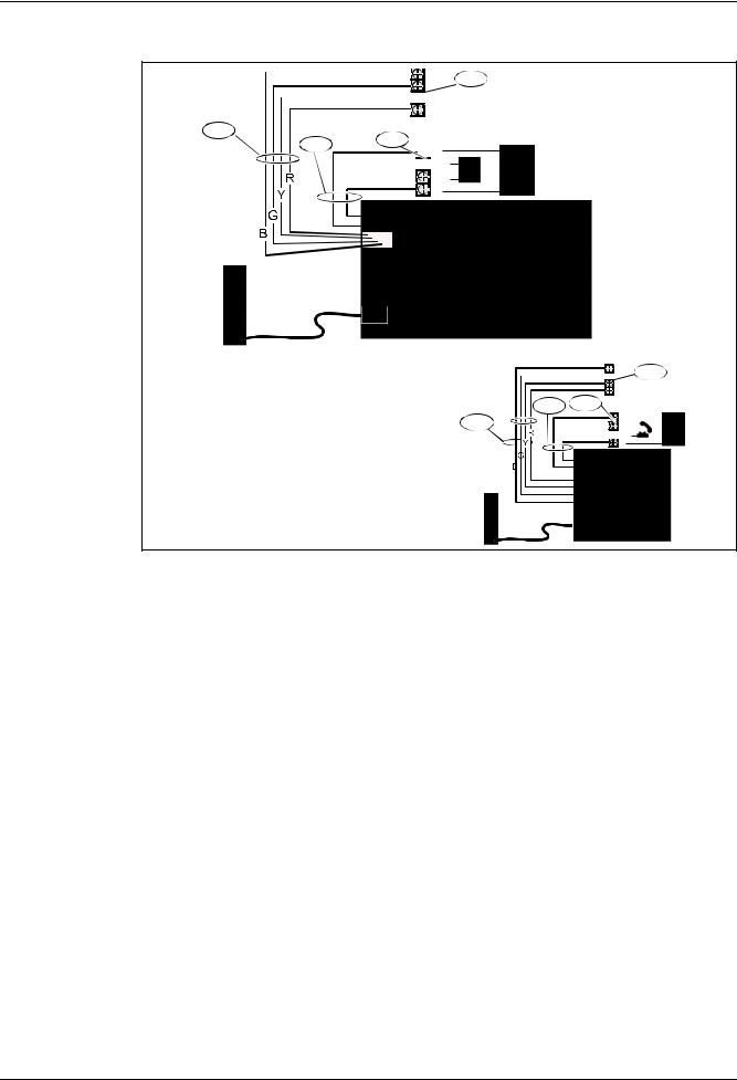
3.4 Connect the ITS-DX4020-G to the Control Panel
Depending on the selected mode of operation, refer to Figure 3.3 below, or Figure 3.4,
Page 15 for wiring connections.
NOTICE!
The bus terminals are shown in only one order. Terminal order is specific to control panel type. Refer to the control panel documentation for more information.
For more information on the modes of operation, refer to Section 2.3 Modes of Operation, page 9.
 B
B
 G 2
G 2
1a  Y
Y
 R
R
B
 G 2
G 2
1b |
|
|
|
|
|
|
Y |
|||
|
|
|
|
|
|
R |
||||
|
|
|
|
|
|
|||||
|
|
|
|
|
|
|
|
|
|
|
|
|
|
|
|
|
|
|
|
|
|
|
|
|
|
|
|
|
|
|
|
|
|
|
|
|
|
|
|
|
|
|
|
|
|
|
|
|
|
|
|
|
|
|
|
|
|
|
|
|
|
|
|
|
|
|
|
|
|
|
|
|
|
|
|
|
|
|
|
|
|
|
|
|
|
|
|
Figure 3.3 |
Connections for IP over GPRS Mode |
|
|
|
|
Callout |
|
Description |
|
|
|
1a |
|
Bus connection from ITS-DX4020-G to the control panel using the supplied |
|
|
Molex cable |
|
|
|
1b |
|
Bus connection from the ITS-DX4020-G to the control panel using the bus |
|
|
power terminals |
|
|
|
2 |
|
Bus power terminals on the control panel |
|
|
|
F01U133268 | 03 | 2010.05 |
Installation and Operation Guide |
Bosch Security Systems, Inc. |

GPRS/GSM IP Communicator Installation | en 15
|
|
|
|
B |
2 |
|||
|
|
|
|
G |
||||
|
|
|
|
|||||
|
|
|
|
Y |
|
|
||
|
|
|
|
|
|
|||
|
|
4 |
|
R |
|
|
||
|
|
|
|
|
||||
|
|
|
R |
|
|
|
|
|
|
3 |
|
|
|
|
|
||
1a |
|
|
RH |
|
|
|
||
|
|
|
|
|
|
|||
 TH
TH
T
|
|
|
|
|
|
|
|
|
|
|
|
|
B |
2 |
||
|
|
|
|
|
|
|
|
|
|
|
|
|
||||
|
|
|
|
|
|
|
|
|
|
|
|
|
||||
|
|
|
|
|
|
|
|
|
|
|
|
|
||||
|
|
|
|
|
|
|
|
|
|
|
|
|
||||
|
|
|
|
|
|
|
|
|
|
|
|
|
||||
|
|
|
|
|
|
|
|
|
|
|
|
|
||||
|
|
|
|
|
|
|
|
|
|
|
|
|
||||
|
|
|
|
|
|
|
|
|
3 |
4 |
|
G |
||||
|
|
|
|
|
|
|
|
|
|
Y |
|
|||||
|
|
|
|
|
|
|
|
|
|
|
|
|
R |
|
||
|
|
|
|
|
|
|
|
|
|
|
|
|
|
|||
|
|
|
|
|
|
|
|
|
|
1b |
|
|
R |
|
|
|
|
|
|
|
|
|
|
|
|
|
|
|
RH |
|
|
||
|
|
|
|
|
|
|
|
|
|
|
|
|
|
|||
 TH
TH
T
|
|
|
|
|
|
|
|
|
|
|
|
|
|
|
|
|
|
|
|
|
|
|
|
|
|
|
|
|
|
|
|
|
|
|
|
|
|
|
Figure 3.4 |
Connections for PSTN (Contact ID) over GSM Mode |
|||||||||||
|
|
|
|
|
|
|
|
|
|
|
|
|
Callout |
Description |
|||||||||||
|
|
|
|
|
|
|
|
|
|
|
|
|
1a |
Power connection from ITS-DX4020-G to the control panel (12 VDC only) using |
|||||||||||
|
the supplied Molex cable |
|||||||||||
|
|
|
|
|
|
|
|
|
|
|
|
|
1b |
Power connection from ITS-DX4020-G to the control panel (12 VDC only) using |
|||||||||||
|
the bus terminals |
|||||||||||
|
|
|
|
|
|
|
|
|
|
|
|
|
2 |
Bus terminals on the control panel |
|||||||||||
|
|
|
|
|
|
|
|
|
|
|
|
|
3 |
PNL/PSTN connection from ITS-DX4020-G to the control panel |
|||||||||||
|
|
|
|
|
|
|
|
|
|
|
|
|
4 |
Phone terminals on the control panel (connect to the Ring [R] and Tip [T] |
|||||||||||
|
terminals) |
|||||||||||
|
|
|
|
|
|
|
|
|
|
|
|
|
Bosch Security Systems, Inc. |
Installation and Operation Guide |
F01U133268 | 03 | 2010.05 |
16 en | Installation |
GPRS/GSM IP Communicator |
|
|
 B
B
2
 Y
Y
R
1a
34  R
R
 RH
RH
 TH
TH
T
B
 G 2
G 2
 Y
Y
R
3 4
1b |
|
R |
|
|
|
|
RH |
|
|
||
|
|
|
|||
 TH
TH
T
|
|
|
|
|
|
|
|
|
|
|
|
|
|
|
|
|
|
Figure 3.5 |
Connections for Dual Wireless Mode |
||||
|
|
|
|
|
|
Callout |
Description |
||||
|
|
|
|
|
|
1a |
Bus connection from ITS-DX4020-G to the control panel using the supplied Molex |
||||
|
connector |
||||
|
|
|
|
|
|
1b |
Bus connection from ITS-DX4020-G to the control panel using the supplied Molex |
||||
|
connector using the bus power terminals |
||||
|
|
|
|
|
|
2 |
Power terminals on the control panel |
||||
|
|
|
|
|
|
3 |
PNL/PSTN connection from ITS-DX4020-G to control panel |
||||
|
|
|
|
|
|
4 |
Phone terminals on the control panel (connect to the Ring [R] and Tip [T] |
||||
|
terminals) |
||||
|
|
|
|
|
|
F01U133268 | 03 | 2010.05 |
Installation and Operation Guide |
Bosch Security Systems, Inc. |
Loading...