


HSLP751UC

Built-in Combination Ovens
Installation Manual
HSLP751UC, HBL57M52UC, HBL8752UC, HBLP752UC,
HBL87M52UC

Table of Contents
Installation instructions
Safety Definitions .......................................................... 2
IMPORTANT SAFETY INSTRUCTIONS ........................ 3
Appliance Handling Safety ................................................. 3
Safety Codes and Standards ............................................. 3
Electric Safety ....................................................................... 3
Related Equipment Safety .................................................. 4
Bosch Combination Ovens ........................................... 5
Before you Begin ........................................................... 5
Tools and Parts Needed ..................................................... 5
Power Requirements and Grounding ............................... 5
For Best Installation ............................................................. 5
Checklist ................................................................................ 6
Cabinet Dimension Requirements ............................... 6
Combination Oven and Speed Oven or Steam
Convection Oven 30” Traditional Installation .................. 7
Combination Oven and Speed Oven or Steam
Convection Oven 30” Flush Mount Installation .............. 7
Removing Packaging .................................................... 8
Packaging Bracket Removal-Left and Right Sides ........ 8
Preparing Ovens ................................................................... 8
Installation ...................................................................... 8
Pre-Assembly of the Combination Oven .......................... 8
Parts Provided ....................................................................... 8
Installation with the Speed Oven or Microwave ............. 9
Installation with the Steam Convection Oven .............. 10
Connecting the Speed Oven or Steam Convection
Oven Electrical Conduit to the Lower Oven ................. 11
Microwave Models ........................................................... 12
Electrical Installation of Combination
Oven-Grounding Instructions .................................... 13
Electrical Connection to Main Power Supply ............... 13
Four-wire Connection ....................................................... 13
Three-wire Connection ..................................................... 13
Installing Combination Oven into Wall Cabinet ....... 14
Remove Lower Oven Door Prior to Installation ........... 14
Correctly Lifting the Combination Oven ........................ 15
Lifting Recommendations ................................................ 15
Placing Combination Oven Into Cabinet Opening ...... 16
Installing the Oven into the Cabinet .............................. 16
Re-Install the Lower Oven Door ..................................... 16
Before Calling Service ...................................................... 16
Rating Label ....................................................................... 17
Lower Oven Rating Label ................................................ 17
Steam Convection Oven Rating Label .......................... 17
Speed Oven and Microwave Rating Label .................. 17
7KLV%RVFK$SSOLDQFHLVPDGHE\
%6++RPH$SSOLDQFHV&RUSRUDWLRQ
0DLQ6WUHHW6XLWH
ZZZERVFKKRPHFRPXV
:HORRNIRUZDUGWRKHDULQJIURP\RX
Safety Definitions
9 WARNING
This indicates that death or serious injuries may
occur as a result of non-observance of this warning.
9 CAUTION
,UYLQH&$
4XHVWLRQV"
NOTICE: This indicates that damage to the appliance or
property may occur as a result of non-compliance with
this advisory.
Note: This alerts you to important information and/or
tips.
This indicates that minor or moderate injuries may
occur as a result of non-observance of this warning.
2
9 IMPORTANT SAFETY INSTRUCTIONS
READ AND SAVE THESE INSTRUCTIONS
IMPORTANT SAFETY INS READ AND SAVE THESE INSTRUCTIONS
IMPORTANT: SAVE THESE INSTRUCTIONS FOR THE
LOCAL ELECTRICAL INSPECTOR’S USE.
INSTALLER: LEAVE THESE INSTALLATION
INSTRUCTIONS WITH THE UNIT FOR THE OWNER.
Electric Safety
WARNING
Before you plug in an electrical cord or turn on power
supply, make sure all controls are in the OFF position.
OWNER: PLEASE RETAIN THESE INSTRUCTIONS FOR
FUTURE REFERENCE.
WARNING
When properly cared for, your new appliance has been
designed to be safe and reliable. Read all instructions
carefully before use. These precautions will reduce the
risk of burns, electric shock, fire and injury to persons.
When using kitchen appliances, basic safety precautions
must be followed including those in the following pages.
WARNING
Do not repair, replace or remove any part of the
appliance unless specifically recommended in the
manuals. Improper installation, service or maintenance
can cause injury or property damage. Refer to this
manual for guidance. All other servicing should be done
by an authorized servicer.
Appliance Handling Safety
CAUTION
▯ Unit is heavy and requires at least two people
or proper equipment to move.
▯ Do not lift appliance by door handle.
▯ Hidden surfaces may have sharp edges. Use
caution when reaching behind or under
appliance.
Do not let cord hang over edge of table or counter or
touch hot surfaces.
Always attach plug to appliance first, then plug cord into
wall outlet. To disconnect, turn any control to “off”, then
remove plug from wall outlet.
Do not operate any appliance with a damaged cord or
plug or after the appliance malfunctions or has been
damaged in any manner. It is unsafe to operate any
appliance with a damaged power cord or plug. If the
appliance has been damaged or malfunctions, safely
disconnect the appliance from the power supply, then
immediately contact an authorized servicer to inspect the
product.
To protect against electrical shock, do not immerse cord,
plugs or other electrical parts in water or other liquid.
For appliances equipped with a cord and plug, do not
cut or remove the ground prong. It must be plugged in to
a matching grounding type receptacle to avoid electrical
shock. If there is any doubt as to whether the wall
receptacle is properly grounded, the customer should
have it checked by a qualified electrician. DO NOT use
an adaptor or extension cord.
If required by the National Electrical Code (or Canadian
Electrical Code), this appliance must be installed on a
separate branch circuit.
Installer-show the owner the location of the circuit
breaker or fuse. Mark it for easy reference.
Safety Codes and Standards
This appliance complies with the latest version of one or
more of the following standards:
▯ UL 858, Household Electric Ranges
▯ UL 923, Microwave Cooking Appliances
▯ UL 507, The Standard for the Safety of Electric Fans
▯ CAN/CSA-C22.2 No. 113-M1984 Fans and Ventilators
It is the responsibility of the owner and the installer to
determine if additional requirements and/or standards
apply to specific installations.
WARNING
Before installing, turn power OFF at the service panel.
Lock service panel to prevent power from being turned
ON accidentally.
Refer to Rating Label for more information. See Rating
Label section for rating label location.
Be sure your appliance is properly installed and
grounded by a authorized technician. Installation,
electrical connections and grounding must comply with
all applicable codes.
3
9 IMPORTANT SAFETY INSTRUCTIONS
READ AND SAVE THESE INSTRUCTIONS
Related Equipment Safety
Remove all tape and packaging before using the
appliance. Discard or recycle packaging materials
according to local codes after unpacking the appliance.
Never modify or alter the construction of the appliance.
For example, do not remove panels or covers.
CAUTION
For units with glass panels, use care when handling
glass to avoid breaking. Broken glass could cause a
laceration type injury.
State of California Proposition 65 Warnings
WARNING
This product contains chemicals known to the State of
California to cause cancer, birth defects or other
reproductive harm.
IMPORTANT SAFETY NOTICE: The California Safe
Drinking and Toxic Enforcement Act requires the
Governor of California to publish a list of substances
known to the state to cause cancer, birth defects or other
reproductive harm, and requires businesses to warn
customers of potential exposure to such substances.
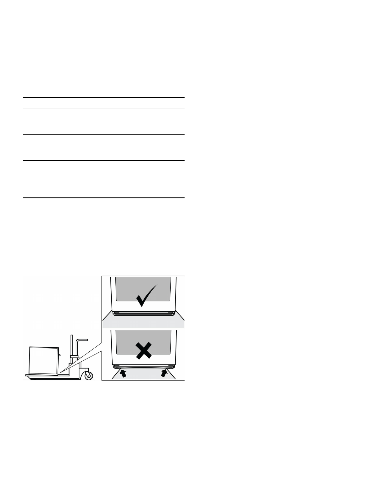
Note: To avoid damage to the oven vent, use the
transport method shown in the picture below.
Support the bottom of the oven from side to side when
moving it into the installation location. Leave the unit
attached to the shipping pallet until it is in front of the
cabinet opening, ready to lift into place.
Save these instructions.
4
Bosch Combination Ovens
The HSLP751UC, HBL57M52UC, HBL87M52UC,
HBL8752UC, and HBLP752UC Bosch combination
ovens are sold as sets, each of which includes two builtin oven components: a traditional wall oven (lower oven)
and an upper oven that is either a built-in speed oven, a
steam convection oven or a microwave.
▯ For ease of installation and improved alignment, the
▯ Each traditional oven component is designed with an
oven-mounted junction box on top, which is used for
connecting the upper oven power cable.
▯ The hardware required for mounting the speed oven or
steam convection oven on top of the traditional oven
will be found inside the traditional oven box.
▯ Each of the oven components has its own rating label,
the component model number, FD number, etc.
oven components are assembled together in the
customer’s home rather than at the factory.
▯ Each of the components are packed in separate
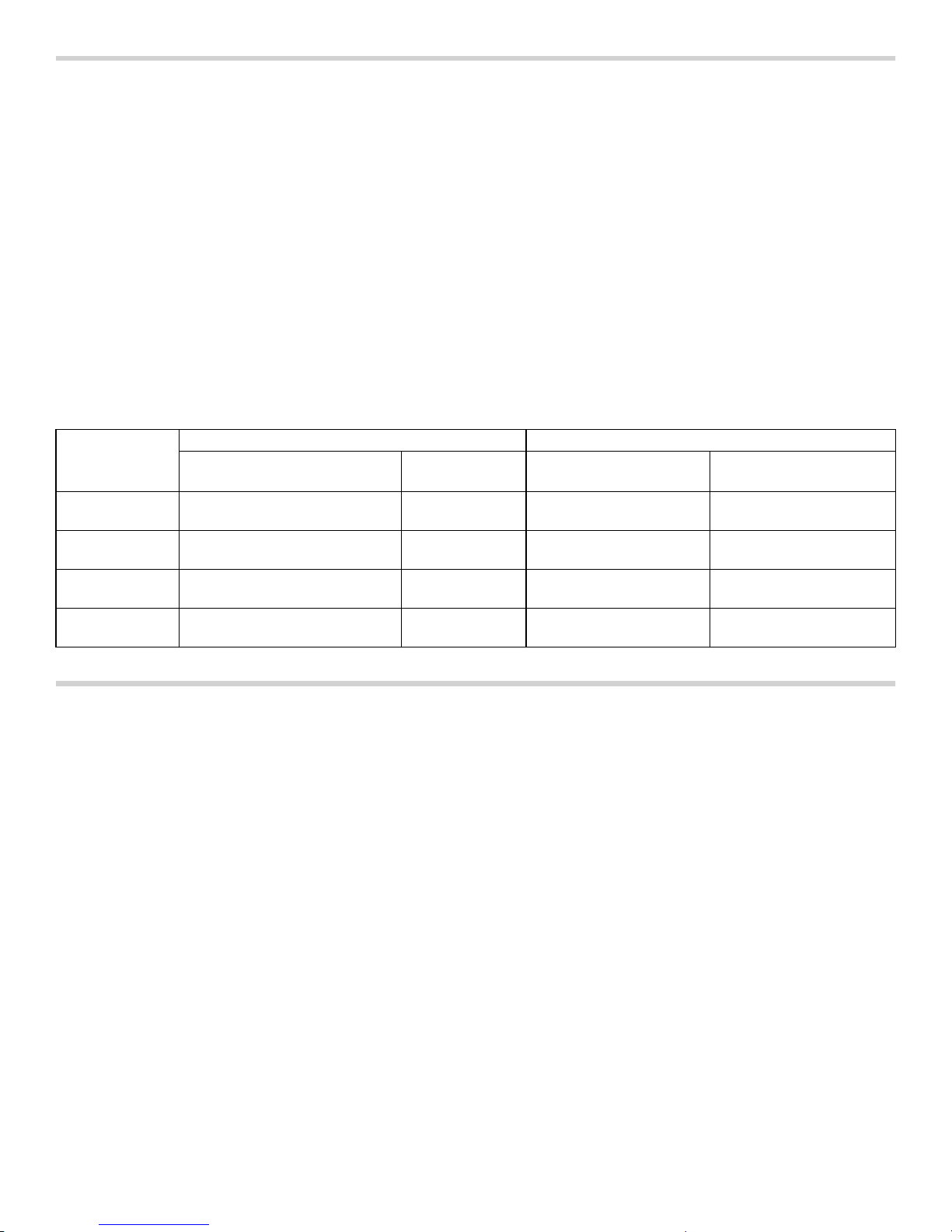
The following table identifies each of the Bosch
combination oven SKUs and its two built-in components.
boxes, which are strapped together prior to shipping.
▯ The combination ovens listed here are approved for
use in a single cutout, using single power connection.
Only the Bosch combination oven components in the
configurations listed in the table below are agencyapproved for use in a single cutout, using single power
connection. Other models cannot be substituted.
Combination
Oven
SKU/Model
HBL57M52UC HBL5451UC HMB50152UC 500 Series Combi Oven
BOSCH Combination Oven Components Reference
Traditional Oven Speed Oven or
Microwave
Built-In Oven/Micro-
wave Combination
Solo MW, 120V, 15 Amp
Microwave Type
& MW
HBL87M52UC HBL8451UC HMB50152UC 800 Series Combi Oven
Solo MW, 120V, 15 Amp
& MW
HBL8752UC HBL8451UC HMC80252UC 800 Series Oven +
240V Speed MW
HBLP752UC HBLP451UC HMCP0252UC Benchmark Oven +
240V Speed MW
Speed MW w/LCD,
240V, 20 Amp
Speed MW w/TFT,
240V, 20 Amp
Before you Begin
Tools and Parts Needed
▯ Phillips-head screwdriver
▯ Star-head screwdriver (T20)
▯ Measuring tape
▯ Drill with bit (1/8”)
▯ Gloves
▯ Utility Knife
Power Requirements and Grounding
The outlet must be properly grounded in accordance with
all applicable codes.
For Best Installation
The oven can be difficult for two people to handle during
installation. It is recommended that three or more people
be available to assist with lifting the unit in to place.
Removal of the lower oven door (to reduce the unit
weight and to provide necessary gripping points) can be
cumbersome unless the detailed door removal
instructions are followed carefully. Do not attempt to
remove the speed oven door or steam convection oven
door.
Please take time to read and follow the instructions
provided for an improved installation experience.
5

Checklist
Use this checklist to verify that you have completed each
step of the installation process. This can help you avoid
mistakes.
▯ Before installing the oven, be sure to verify the cabinet
dimensions are correct and the required electrical
connections are present.
▯ Refer to additional information in this manual
regarding Safety, Cabinet Dimensions, Removing
Packaging, Electrical Installation, Testing the
Installation and Customer Service.
▯ Remove the lower oven door to reduce the unit weight
and to provide access to gripping points for lifting. See
“Remove Lower Oven Door Prior to Installation”
information.
▯ Move the oven units into place in front of the cabinet
opening, leaving the bottom packaging on the units to
avoid damaging flooring.
▯ Remove the Star-head screws (T-20 size using Star-
head screwdriver) holding the speed microwave oven
or steam convection oven to the base of its carton.
▯ Assemble the two units of the combination oven. See
“Pre-Assembly of the Combination Oven”.
▯ Connect the power cable from the lower oven to the
junction box in the cabinet.
▯ Remove the Star-head screws (T-20 size using Star-
head screwdriver) holding the lower oven to the base
of its carton.
▯ Team-lift the unit directly into the cabinet cutout taking
care not to pinch fingers, scratch arms or hands.
▯ Slide the unit all the way in to place.
▯ Fasten the combination unit to the cabinetry opening
with the screws supplied (using Philips screwdriver).
▯ Reinstall the oven door removed in Step 3 above.
▯ Consult the complete installation instructions and
follow the remainder of the procedures listed,
including performing operation test.
▯ INSTALLER- Leave the literature pack and the
accessories with the customer.
Cabinet Dimension Requirements
It is good practice, when an oven is installed at the end
of a cabinet run, adjacent to a perpendicular wall, or
cabinet door, to allow at least 1/4” (6.4 mm) space
between the side of the oven and the wall/door.
For oven support, install 2x4s extending front to back
flush with the bottom and the sides of the opening. The
supporting base must be well secured to the floor/
cabinet and level.
Junction boxes can be located anywhere within reach of
the oven’s power cable.
The cabinet base must be flat and capable of supporting
the weight of the combination oven up to 429 lbs. (195
kg).
6
 Loading...