


 Loading...
Hood
Installation Manual
HUI50351UC, HUI56551UC

Table of Contents |
|
9 Safety Definitions ..................................................... |
3 |
IMPORTANT SAFETY INSTRUCTIONS ........................ |
4 |
Appliance Handling Safety ................................................. |
5 |
Safety Codes and Standards ............................................. |
5 |
Electric Safety ....................................................................... |
5 |
Related Equipment Safety .................................................. |
6 |
Proposition 65 Warning: ..................................................... |
6 |
Causes of Damage ........................................................ |
7 |
Protecting the environment .......................................... |
7 |
General Notes ................................................................ |
7 |
Exhaust air mode ................................................................. |
7 |
Ventilation line ....................................................................... |
7 |
Electrical connection ........................................................... |
7 |
Before you begin ........................................................... |
8 |
Tools and parts needed ...................................................... |
8 |
Parts included ....................................................................... |
8 |
Appliance dimensions ......................................................... |
8 |
Safety clearances ................................................................. |
9 |
Planning air channels ................................................. |
10 |
Preparing the appliance .............................................. |
11 |
Air outlet position on top .................................................. |
11 |
Air outlet position at rear ................................................. |
11 |
Preparing the units ...................................................... |
12 |
Installing the appliance ............................................... |
13 |
Connect appliance ....................................................... |
14 |
Establishing the connection for the exhaust air .......... |
14 |
Establishing the connection for the circulated air ....... |
14 |
Electrical Installation ......................................................... |
15 |
Removing the appliance ............................................. |
16 |
Customer service ........................................................ |
16 |
Additional information on products, accessories, replacement parts and services can be found at www.bosch-home.com and in the online shop
www.bosch-home.com/us/store
2

9Safety Definitions
9WARNING
This indicates that death or serious injuries may occur as a result of non-observance of this warning.
9CAUTION
This indicates that minor or moderate injuries may occur as a result of non-observance of this warning.
NOTICE: This indicates that damage to the appliance or property may occur as a result of non-compliance with this advisory.
Note: This alerts you to important information and/or tips.
3

9 IMPORTANT SAFETY INSTRUCTIONS
READ AND SAVE THESE INSTRUCTIONS
INSTALLER: LEAVE THESE INSTRUCTIONS WITH THE APPLIANCE AFTER INSTALLATION IS COMPLETE.
IMPORTANT: SAVE THESE INSTRUCTIONS FOR THE LOCAL ELECTRICAL INSPECTOR'S USE.
WARNING
If the information in this manual is not followed exactly, fire or shock may result causing property damage or personal injury.
WARNING
Do not repair, replace or remove any part of the appliance unless specifically recommended in the manuals. Improper installation, service or maintenance can cause injury or property damage. Refer to this manual for guidance. All other servicing should be done by an authorized servicer.
WARNING
WARNING – TO REDUCE THE RISK OF FIRE, ELECTRIC SHOCK, OR INJURY TO PERSONS, OBSERVE THE FOLLOWING:
Installation work and electrical wiring must be done by qualified person(s) in accordance with all applicable codes and standards, including fire-rated construction.
Sufficient air is needed for proper combustion and exhausting of gases through the flue (chimney) of fuel burning equipment to prevent back drafting. Follow the heating equipment manufacturer’s guideline and safety standards such as those published by the National Fire Protection Association (NFPA), and the American Society for Heating, Refrigeration and Air Conditioning Engineers (ASHRAE), and the local code authorities.
When cutting or drilling into wall or ceiling, do not damage electrical wiring and other hidden utilities.
Ducted fans must always be vented to the outdoors.
WARNING
The applicable regulations of the energy supply companies and the regional construction regulations must be observed when installing the hood.
WARNING
RISK OF FIRE
Grease deposits in the grease filter can catch fire. Never work with a naked flame near the appliance (e.g. flambéing). Install the unit near a heat-producing appliance for solid fuels (e.g. wood or coal) only if there is a closed, non-detachable cover. There must be no flying sparks.
WARNING
RISK OF FIRE
Operating several gas burners at the same time gives rise to a great deal of heat. The ventilation appliance may become damaged or catch fire. The ventilation appliance must only be combined with gas burners that do not exceed the maximum total output of 61,000 BTU/hr (18 kW). If 41,000 BTU/hr (12 kW) is exceeded, the local regulations concerning room ventilation, room size, and combination with ventilation devices in exhaust and recirculating operation must be followed.
WARNING
To reduce risk of fire and to properly exhaust air, be sure to duct air outside. Do not vent exhaust air into spaces within walls, ceilings, attics, crawl spaces or garages.
WARNING
To reduce the risk of fire, use only metal ductwork.
WARNING
When the hood is operated in exhaust-air mode simultaneously with a different burner which also makes use of the same chimney (such as gas, oil or coal-fired heaters, continuous-flow heaters, hot-water boilers) care must be taken to ensure that there is an adequate supply of fresh air which will be needed by the burner for combustion.
Safe operation is possible provided that the under pressure in the room where the burner is installed does not exceed 4 Pa (0.04 mbar).
This can be achieved if combustion air can flow through non-lockable openings, e.g. in doors, windows and via the air-intake/exhaust-air wall box or by other technical measures, such as reciprocal interlocking, etc.
4
9 IMPORTANT SAFETY INSTRUCTIONS
READ AND SAVE THESE INSTRUCTIONS
WARNING
Avoid carbon monoxide poisoning – Provide adequate air intake so combustion gases are not drawn back into the room.
An air-intake/exhaust-air wall box by itself is no guarantee that the limiting value will not be exceeded.
Note: When assessing the overall requirement, the combined ventilation system for the entire household must be taken into consideration. This rule does not apply to the use of cooking appliances, such as cooktops and ovens.
CAUTION
For general ventilating use only. Do not use to exhaust hazardous or explosive materials and vapors.
Risk of damage from condensation back flow. Install exhaust vent at a slight downward slope away from the appliance (1° slope).
Appliance Handling Safety
Unit is heavy and requires at least two people or proper equipment to move.
Hidden surfaces may have sharp edges. Use caution when reaching behind or under appliance.
WARNING
RISK OF INJURY
The appliance may fall from the wall if it is not attached properly. All fastening components must be fixed firmly and securely in place.
Safety Codes and Standards
This appliance complies with the latest version of one or more of the following standards:
UL 507 - Electric Fans
CAN/CSA C22.2 No. 113 - Fans and Ventilators
It is the responsibility of the installer to determine if additional requirements and/or standards apply to specific installations.
Electric Safety
WARNING
RISK OF ELECTRICAL SHOCK OR FIRE
Frame grounded to neutral through a ground strap. Grounding through the neutral conductor is prohibited for new branch-circuit installations (1996 NEC), mobile homes, and recreational vehicles, or in an area where local codes prohibit grounding through the neutral conductor.
For installations where grounding through the neutral conductor is prohibited,
a.disconnect the link from the neutral,
b.use grounding terminal or lead to ground unit,
c.connect neutral terminal to lead branch circuit neutral in usual manner (when the appliance is to be connected by means of a cord kit, use a UL listed 4- conductor cord for this purpose).
GROUNDING INSTRUCTIONS
This appliance must be grounded. Grounding reduces the risk of electric shock by providing a safe pathway for electric current in the event of a short circuit.
The appliance must be connected to a grounded, metallic, permanent wiring system, or an equipment grounding conductor should be run with the circuit conductors and connected to the equipment grounding terminal or lead on the appliance.
WARNING
Improper grounding can result in a risk of electric shock. Consult a qualified electrician if the grounding instructions are not completely understood, or if doubt exists as to whether the appliance is properly grounded. Do not use an extension cord. If the power supply cord is too short, have a qualified electrician install an outlet near the appliance.
WARNING
Before you plug in an electrical cord or turn on power supply, make sure all controls are in the OFF position.
5
9 IMPORTANT SAFETY INSTRUCTIONS
READ AND SAVE THESE INSTRUCTIONS
WARNING
RISK OF ELECTRICAL SHOCK OR FIRE
Frame grounded to neutral through a ground strap. Grounding through the neutral conductor is prohibited for new branch-circuit installations (1996 NEC), mobile homes, and recreational vehicles, or in an area where local codes prohibit grounding through the neutral conductor.
For installations where grounding through the neutral conductor is prohibited,
a.disconnect the link from the neutral,
b.use grounding terminal or lead to ground unit,
c.connect neutral terminal to lead branch circuit neutral in usual manner (when the appliance is to be connected by means of a cord kit, use a UL listed 4- conductor cord for this purpose).
If required by the National Electrical Code (or Canadian Electrical Code), this appliance must be installed on a separate branch circuit.
WARNING
To reduce the risk of fire or electric shock, do not use this fan with any solid-state speed control device.
Installer – show the owner the location of the circuit breaker or fuse. Mark it for easy reference.
Before installing, turn power OFF at the service panel. Lock service panel to prevent power from being turned ON accidentally.
WARNING
TO REDUCE THE RISK OF FIRE, ELECTRIC SHOCK, OR INJURY TOPERSONS, OBSERVE THE FOLLOWING:
Use this unit only in the manner intended by the manufacturer. If you have questions, contact the manufacturer.
Related Equipment Safety
Remove all tape and packaging before using the appliance. Destroy the packaging after unpacking the appliance. Never allow children to play with packaging material.
To ensure safe operation of the appliance, it must be installed by a qualified technician according to these installation instructions. The installer is liable for any damage resulting from incorrect installation.
Never modify or alter the construction of the appliance. For example, do not remove leveling legs, panels, wire covers or anti-tip brackets/screws.
Proposition 65 Warning:
This product may contain a chemical known to the State of California, which can cause cancer or reproductive harm. Therefore, the packaging of your product may bear the following label as required by California:
67$7( 2) &$/,)251,$ 352326,7,21 :$51,1*
:$51,1*
&DQFHU DQG 5HSURGXFWLYH +DUP ZZZ3 :DUQLQJV FD JRY
Before servicing or cleaning unit, switch power off at service panel and lock out the service disconnect to prevent power from being switched on accidentally.
When the service disconnect cannot be locked, securely fasten a prominent warning device, such as a tag, to the service panel.
Be sure your appliance is properly installed and grounded by a qualified technician. Installation, electrical connections and grounding must comply with all applicable codes.
WARNING
RISK OF ELECTRIC SHOCK
Parts inside the appliance can have sharp edges. The connection cable can be damaged. Do not bend or pinch connection cables during installation.
6

Causes of Damage
NOTICES:
Risk of damage due to corrosion. Always turn appliance on when cooking to avoid condensation buildup. Condensation can lead to corrosion damages.
Always replace defective bulbs immediately to avoid an overload of the remaining bulbs.
Risk of damage due to ingress of humidity into the electronic circuitry. Never clean operator controls with a wet cloth.
Surface damage due to incorrect cleaning. Clean stainless steel surfaces in the grind direction only. Do not use any stainless steel cleaners for operator controls.
Surface damage due to strong or abrasive cleaning agents. Never use strong and abrasive cleaning agents.
Risk of damage from condensation back flow. Install exhaust vent at a slight downward slope away from the appliance (1° slope).
Protecting the environment
Unpack the appliance and dispose of the packaging in an environmentally friendly manner.
General Notes
Exhaust air mode
Note: Ventilation may not exit through an already operational smoke or exhaust chimney, nor a duct used for ventilating furnace installation areas.
If the ventilation is intended to pass through a smoke or exhaust chimney that is not in operation, the responsible area heating inspector must give approval.
If the ventilation passes through an external wall, use a telescope wall sleeve.
Ventilation line
Note: The installer is responsible for proper installation and functionality related to the duct section. Improper installation affecting the use of the appliance is not the responsibility of the appliance manufacturer.
The appliance achieves its optimum performance by means of a short, straight exhaust air duct and as large a duct diameter as possible.
As a result of long rough exhaust air ducts, too many duct bends or duct diameters that are smaller than 6" (150 mm), the optimum extraction performance is not achieved and fan noise is increased.
The ducts or hoses for laying the exhaust air line must consist of non-combustible material.
Round ducts
An inside diameter of 6" (150 mm) is recommended, with a minimum being 4 _" (120 mm).
Flat ducts
The inner cross-section must correspond to the diameter of the round ducts.
dia. 6" (150 mm) approx. 27^sq in (177 cm2) dia. 4 _" (120 mm) approx. 26_ sq in (113 cm2)
Flat ducts should have no sharp deflections.
Use sealing strip for deviating duct diameters.
Electrical connection
9WARNING
RISK OF ELECTRIC SHOCK
Parts inside the appliance can have sharp edges. The connection cable can be damaged. Do not bend or pinch connection cables during installation.
A 120 volt, 60 Hz AC-only electrical supply is required on a separate 15 amp fused circuit.
Before connecting the appliance, check the household electricity installation. Ensure sufficient fuse protection of the household electricity installation. The voltage and frequency of the appliance must match the electrical installation (see rating plate).
The appliance complies with protection class 1 and must only be operated in conjunction with a protective conductor terminal.
An all-pole isolating switch with at least a X" (3 mm) contact gap must be fitted in the installation. This must remain accessible after installation.
Only a qualified electrician following the appropriate codes and regulation may install, lay, or replace the connecting cables.
7

Follow all valid standards and laws.
Ensure that the electrical connection meets the requirements of the latest version of all applicable standards and laws in the appropriate country, especially the following standards: National Electrical Code, ANSI/ NFPA 70, or CSA Standards C22.1-94, Canadian Electrical Code, Part 1 and C22.2 No.0-M91.
Have a qualified electrical technician check the grounding of the appliance.
Do not ground with a gas line.
No fuse protection in the neutral or grounding circuit.
Keep the installation instructions. Only connect the appliance with a copper conductor. If possible, connect the appliance to a metal cable guide directly to the fuse box.
Ensure that the wire diameter meets the requirements of the latest version of all applicable standards and laws in the appropriate country, especially the following standards: National Electrical Code, ANSI/NFPA 70, or CSA Standards C22.1-94, Canadian Electrical Code, Part 1 and C22.2 No.0-M91.
Put a protecting hose that is listed in the U.L. or C.S.A. on both ends of the connecting cable, that is, on the appliance and on the fuse box.
Before you begin
Tools and parts needed
Saber Saw or Jig Saw
Drill
1 1/4" Wood Drill Bit
Pliers
Phillips Screwdriver
Wire Stripper or Utility Knife
Metal Snips
Measuring Tape or Ruler
Level
Pencil
Caulking Gun
Duct Tape
Parts included
Appliance dimensions
PP
PP
¼
PP
PP |
PP |
8

Safety clearances
9WARNING
RISK OF FIRE
Grease deposits in the grease filter can catch fire. The given safety clearance must be observed to avoid heat buildup. Observe the specifications for your cooking appliance. If gas and electric cooktops are used together, the largest given clearance applies.
The appliance may only be installed directly next to a cabinet or wall on one side. The wall or cabinet clearance must be at least 2" (50 mm).
The clearance between the shelf on the cooktop and the bottom of the extractor hood may not be less than 24" (610 mm) in the case of electric cooktops and 25 3/5" (650 mm) in case of gas or combined ranges.
If the installation instructions for the gas cooking appliance specify a larger distance, that distance must be observed.
PP
PP
9

Planning air channels
For satisfactory performance the duct run should not exceed 50 equivalent feet if ducted using the required minimum 6" round duct.
|
|
6,=( (48,9$/(17 48$17,7< |
727$/ |
|
|
6,=( (48,9$/(17 48$17,7< |
727$/ |
||||
'8&7 3,(&(6 |
(48,9$/(17 |
'8&7 3,(&(6 |
(48,9$/(17 |
||||||||
|
|
|
/(1*7+ |
86(' |
/(1*7+ |
|
|
|
/(1*7+ |
86(' |
/(1*7+ |
|
|
|
|
|
|
|
|
|
|
||
|
|
µ |
· |
|
|
|
éµ[ µ |
|
|
|
|
|
5281' |
µ |
· |
|
|
|
&(17(5 |
|
|
|
|
|
675$,*+7 |
µ |
· |
|
|
|
5(9(56( |
1 $ |
· |
|
|
· |
|
|
|
|
|
|
(/%2: |
|
|
|
|
|
µ |
· |
|
|
|
/()7 |
|
|
|
|
|
|
|
|
|
|
|
|
|
|
|||
|
éµ[ µ |
· |
|
|
|
éµ[ µ |
|
|
|
|
|
|
675$,*+7 |
|
|
|
&(17(5 |
|
|
|
|
||
|
|
|
|
|
1 $ |
· |
|
|
|||
|
éµ[ µ |
|
|
|
|
5(9(56( |
|
|
|||
· |
· |
|
|
|
(/%2: |
|
|
|
|
||
675$,*+7 |
|
|
|
5,*+7 |
|
|
|
|
|||
|
|
|
|
|
|
|
|
|
|||
|
|
µ |
· |
|
|
|
éµ[ µ |
|
|
|
|
|
|
|
|
|
|
5,*+7 |
1 $ |
· |
|
|
|
|
5281' |
µ |
· |
|
|
|
5(9(56( |
|
|
||
|
(/%2: |
µ |
· |
|
|
|
(/%2: |
|
|
|
|
|
|
|
|
|
|
|
|
|
|
||
|
|
µ |
· |
|
|
|
éµ[ µ |
|
|
|
|
|
|
|
|
|
|
/()7 |
|
|
|
|
|
|
5281' |
µ |
· |
|
|
|
5(9(56( |
1 $ |
· |
|
|
|
(/%2: |
µ |
· |
|
|
|
(/%2: |
|
|
|
|
|
|
|
|
|
|
|
|
|
|
||
|
|
|
|
|
|
|
5281' |
µ |
|
|
|
|
|
|
|
|
|
|
µ |
|
|
|
|
|
|
1 $ |
· |
|
|
|
:$// &$3 |
· |
|
|
|
|
éµ[ µ |
|
|
|
µ |
|
|
||||
|
|
|
|
|
|
0RGHO :& |
|
|
|
||
|
(/%2: |
|
|
|
|
|
0RGHO :& µ |
|
|
|
|
|
|
|
|
|
|
|
5281' |
µ |
|
|
|
|
|
1 $ |
· |
|
|
|
µ |
· |
|
|
|
|
éµ[ µ |
|
|
|
522) |
|
|
||||
|
|
|
|
|
|
&$3 |
µ |
|
|
|
|
|
(/%2: |
|
|
|
|
|
|
|
|
||
|
|
|
|
|
|
|
|
|
|
||
|
éµ[ µ |
|
|
|
|
|
· |
|
|
|
|
|
1 $ |
· |
|
|
|
/21* |
· |
|
|
||
|
)/$7 |
|
|
|
|
|
|||||
|
|
|
|
éµ[ µ )/(; |
|
|
|||||
|
(/%2: |
|
|
|
|
|
|
|
|
||
|
|
|
|
|
|
02'(/ 5' |
|
|
|
||
|
|
|
|
|
|
|
|
|
|
||
|
5281' 72 |
µ |
· |
|
|
|
éµ |
|
|
|
|
|
|
|
µ |
éµ[ µ |
· |
|
|
||||
|
éµ[ µ |
|
|
|
|
|
72 5281' |
|
|
||
|
µ |
· |
|
|
|
|
|
|
|||
|
|
|
|
|
µ |
|
|
|
|
||
|
|
|
|
|
|
|
|
|
|
|
|
|
éµ[ µ |
µ |
· |
|
|
|
éµ[ µ |
|
|
|
|
|
72 5281' |
|
|
|
|
|
· |
|
|
||
|
|
|
|
|
|
:$// &$3 |
|
|
|||
|
|
µ |
· |
|
|
|
|
|
|
||
|
|
|
|
|
|
|
|
|
|
||
|
5281' 72 |
µ |
· |
|
|
|
µ ,Q /LQH |
|
|
|
|
|
éµ[ µ |
|
|
|
|
|
%DFNGUDIW |
· |
|
|
|
|
(/%2: |
|
|
|
|
|
|
|
|||
|
µ |
· |
|
|
|
'DPSHU |
|
|
|
|
|
|
éµ[ µ |
µ |
· |
|
|
|
éµ[ µ |
|
|
|
|
|
72 5281' |
|
|
|
5RRI -DFN |
|
· |
|
|
||
|
|
|
|
|
|
|
|
|
|||
|
(/%2: |
µ |
· |
|
|
|
6KXWWHU |
|
|
|
|
|
|
|
|
|
|
|
0RGHO 5- |
|
|
|
|
|
|
|
|
|
|
|
|
|
|
727$/ |
|
10 |
|
|
|
|
|
|
|
|
|
|
|
Preparing the appliance
In order to better suit the installation situation, you can position the air outlet at the top or at the rear by turning the motor unit.
Air outlet position on top
Note: In the appliance's condition as delivered, you can mount the exhaust air duct at the top on the extractor hood.
2.Carefully lift motor unit out of the cover body.
3.Turn the motor unit.
4.Screw the motor unit to the cover body.
The air outlet is positioned at the rear.
Air outlet position at rear
9WARNING
RISK OF INJURY
Components inside the appliance may have sharp edges. Wear protective gloves.
1. Remove the screws of the motor unit.
11
Preparing the units
Fitted units must be heat-resistant up to 194° F (90 °C). The stability of the fitted unit must also be ensured after the cut-out work.
After the cutting out work is complete, remove the shavings.
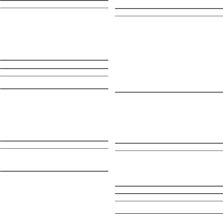
1. Make the cut-out in the fitted unit.
D
PP
D
 PP
PP
ô ô
PP
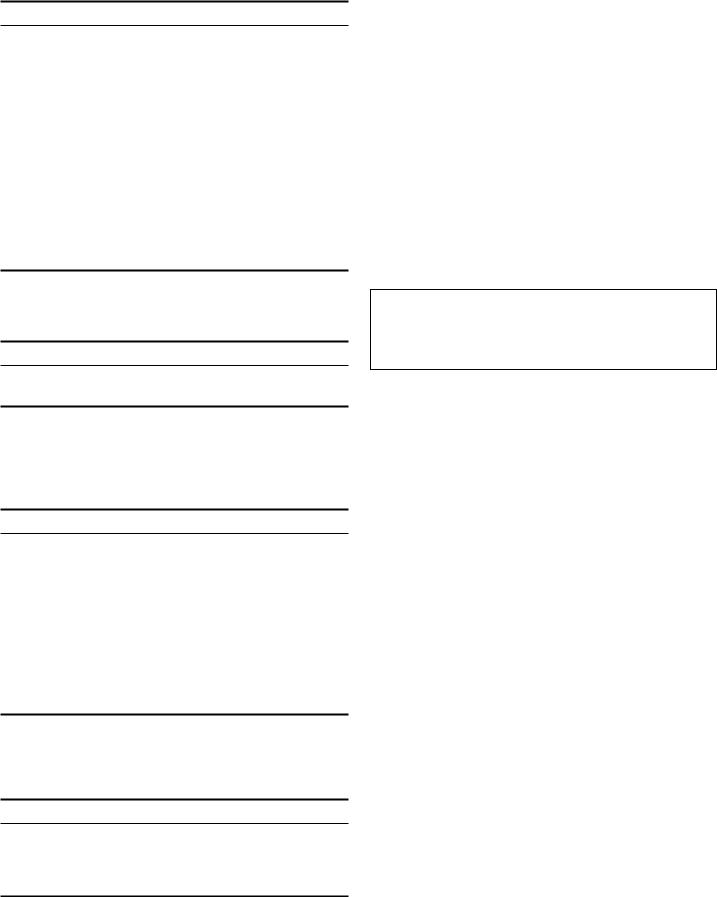
2.Make the cut-out for the exhaust air duct. Exhaust air opening above the fitted unit:
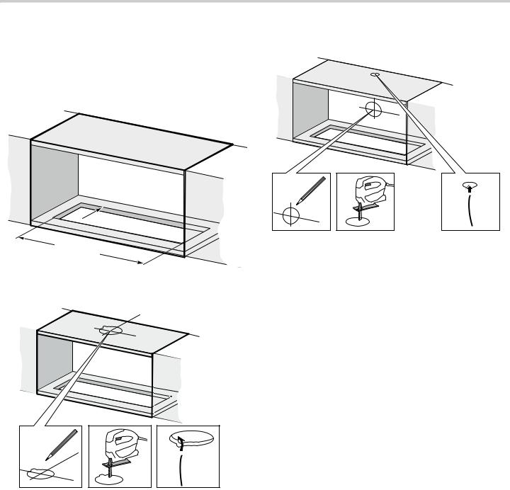
Exhaust air opening behind the fitted unit:
12

Installing the appliance
1. Press the back-flow flap onto the air outlet.
2. Insert the appliance into the cut-out.
3. Pull out the filter drawer.
4. Remove the two rear grease filters.
5. Tighten both fastening screws.
6.Fasten the plastic plate on the extractor hood in order to protect the fitted unit from cooking steam.
Note: Shorten the plastic plate to the depth of the fitted unit.
13

7.Optional for air recirculation:
Place activated charcoal filters on the motor and turn.
Order number for activated charcoal filter: HIUF06UC
Connect appliance
Notes
With operation in extraction air mode , a back-pressure flap should be installed. If no back-pressure flap is included with the appliance, it can be ordered from a specialist retailer.
If the exhaust air is conveyed through the outer wall, a telescopic wall box should be used.
If an aluminum duct is used, smooth the connection area beforehand.
Exhaust air duct dia. 6" (150 mm) (recommended size).
Establishing the connection for the exhaust air
Note: If an aluminum duct is used, smooth the connection area beforehand.
1.Attach the exhaust air duct directly to the air duct connector.
2.Connect it to the air extractor opening.
3.Seal the joints appropriately.
Establishing the connection for the circulated air
Notes
If an aluminum duct is used, smooth the connection area beforehand.
Fit the air guide grille so that the air can flow out freely.
1.Attach the exhaust air duct directly to the air duct connector.
2.Establish the connection to the opening on the fitted unit.
3.Screw the air guide grill to the fitted unit.
4.Seal the joints appropriately.
14

Electrical Installation
9WARNING
The electrical connection of the appliance must be carried out by a qualified electrician.
9CAUTION
Before installing, turn off power supply at the service panel. Lock service panel to prevent power from being turned on accidentally.
9WARNING
Local codes may vary; installation, electrical connections and grounding must comply with all applicable local codes.
If local codes permit grounding through the electrical supply neutral, connect both the white neutral wire and the bare ground wire from the hood to the white neutral electrical supply wire.
Three-wire 120 V Connection
Remove the cover from the field wiring compartment with a phillips screwdriver. Feed the power supply cable through the electrical knockout.
 JUHHQ RU EDUH ZLUH
EODFN ZLUHV
MXQFWLRQ ER[
JURXQG 
SRZHU VXSSO\
 ZKLWH ZLUHV
\HOORZ JUHHQ ZLUH 
 FDEOH IURP KRRG
Connect the power supply cable to the rangehood cable:
Connect white wire from hood to white wire from power supply in junction box.
Connect black wire from hood to black wire from power supply in junction box.
Connect green or bare neutral wire from power supply to ground wire nut in junction box.
9WARNING
RISK OF ELECTRIC SHOCK
Do not under any circumstances damage or remove the green/yellow wire. Non-adherence can cause deadly injuries or electric shock.
The conduit cable, where connected at the hood, flexes.
To maintain serviceability, the flex conduit must not be shortened and should be routed to permit temporary removal of the hood.
Using the 4 holes provided, screw the field wiring compartment to the wall or cabinet as dictated by your power supply cable location (screws not provided). Replace the cover.
15
Loading...