


Integra SHX43C02UC
Bosch Integra SHX43C02UC, Integra SHX43C06UC, Integra SHX43C05UC, SHY66, SHX99A Installation Instructions Manual
...
YOUR LIFE. OUR INSPIRATION.
Power
On/Off
Delay
Start
Hours
Top
Rack
Only
Cancel
Drain
Power
Scrub
Plus
Scrub
Wash
Regular
Wash
Delicate/
Econo
Quick
Wash
Rinse
& Hold
Refill
Rinse
Agent
Cycle Countdown
Dishwasher Installation Instructions
Instructions d’installation du lave-vaisselle
Instrucciones de instalación para lavadora de platos
Use and Care Manual located on reverse side
Tourner le guide pour les instructions d’utilisation et d’entretien
Voltee el manual para encontrar las instrucciones de uso y cuidado
9000060333 (8503)

Table of Contents / Important Instructions
Table of Contents
IMPORTANT INSTRUCTIONS ................................ 1
Tools Needed ........................................................... 2
Materials Needed .....................................................2
Materials Supplied ...................................................3
Enclosure Preparation ............................................. 4
Electrical Preparation .............................................. 5
Plumbing Preparation ........................................... 6-7
Dishwasher Preparation ........................................ 7-8
Door Panel Installation .............................................9
Important Safety Instructions
WARNING
To avoid possible injury or property damage,
OBSERVE ALL WARNINGS AND CAUTIONS.
These instructions are intended for use by
qualified installers only.
The dishwasher must be installed by a qualified
service technician.
• In addition to these instructions, the dishwasher
shall be installed to meet all electrical and
plumbing codes and ordinances (both national and
local).
Read these installation instructions completely
and follow them carefully. They will save you time
and effort and help to ensure safety and optimum
dishwasher performance.
CAUTION
If the dishwasher is installed in a location that
experiences freezing temperatures (e.g., in a
holiday home), you must drain all the water
from the dishwasher’s interior. Water system
ruptures that occur as a result of freezing are
not covered by warranty.
Placing the Dishwasher ......................................... 10
Securing the Dishwasher ....................................... 10
Drain Hose Connection .......................................... 11
Hot Water Connection ............................................12
Electrical Connection........................................ 13-14
Door Tension Adjustment ....................................... 14
Base and Toe Panel .......................................... 14-15
Final Instructions ................................................... 15
Customer Service .................................................. 16
IMPORTANT
• The dishwasher drain hose must be installed
with a portion of it at least 20” (508mm) off the
cabinet floor; otherwise the dishwasher may not
drain properly.
• This dishwasher is intended for residential use
only, and should not be used in commercial food
service establishments.
• NEW INSTALLATION - If the dishwasher is a
new installation, most of the work must be done
before the dishwasher is moved into place.
• REPLACEMENT - If the dishwasher is replacing
another dishwasher, check the existing
dishwasher connections for compatibility with
the new dishwasher, and replace parts as
necessary.
Inspect the Dishwasher
After unpacking the dishwasher and prior to
installation, thoroughly inspect the dishwasher for
possible freight or cosmetic damage. Report any
damage immediately. Cosmetic defects must be
reported within 5 days of installation.
NOTE: Do not discard any bags or items that come
with the original package until after the entire
installation has been completed.
1
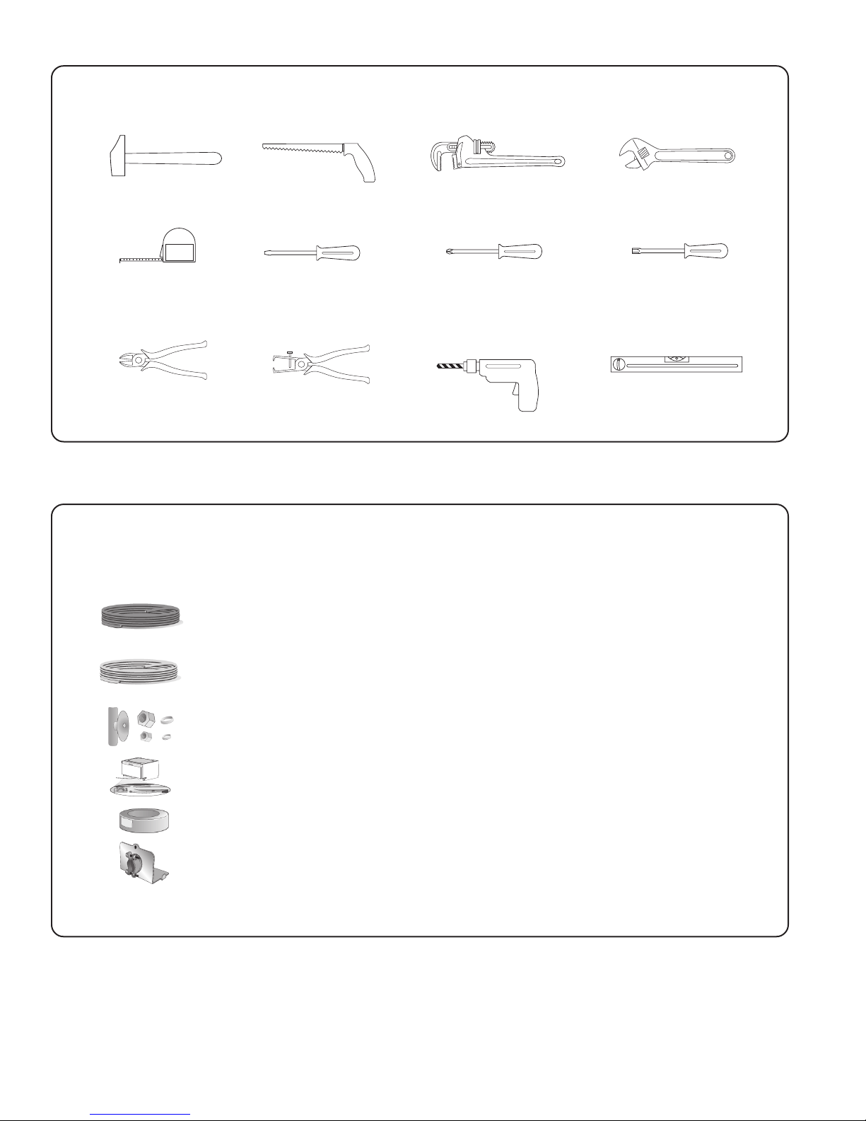
TOOLS NEEDED
Tools and Materials Needed
Hammer Hole Saw
Tape Measure
Wire Cutter
Slot Screwdriver
Wire Stripper
Phillips Screwdriver
Drill
MATERIALS NEEDED
(Additional materials may be required to comply with local codes.)
Pipe Wrench
Adjustable Wrench
Torx Screwdriver
Level
Electrical Supply Cable - Minimum #14 AWG, 2 conductor, 1 ground, insulated copper
conductors rated 75°C or higher.
Hot Water Supply Line - Minimum 3/8” O.D. copper tubing or metal braided dishwasher
supply line.
Shut-off valve and fittings appropriate for hot water supply line (copper tubing/
compression fitting, or braided hose).
90° elbow with 3/8” N.P.T. male threads on one leg, and sized to fit your water supply
line (copper tubing/compression fitting, or braided hose) on the other leg.
Teflon tape or other pipe thread compound to seal plumbing connections.
UL listed conduit connector or strain relief.
2

Materials Supplied
MATERIALS SUPPLIED
Accessory Parts Supplied
Accessory parts for your dishwasher come in one or more plastic bags that are outlined below.
NOTE: Make sure you save all the bags until you have completed your installation.
Manual Set Bag
A Manual Set Bag is provided with each dishwasher
and includes:
A Use & Care Instructions and Installation
Instructions (both manuals may be included
in a single “flip-style” book
B Quick Reference Guide (select models)
C Extra Tall Item Sprinkler
D SHI and SHV Installation Template (SHI and SHV
models only)
E White Cotton Insulation Strip (SHY66 and
SHX99A models only)
Dishwasher Installation Kit
A Dishwasher Installation Kit is provided with each
dishwasher and includes:
F Toe Panel Screws (2 black machine screws)
G Counter Top Mounting Brackets (2 “L” shaped
metal brackets)
H Mounting Bracket Screws (2 silver wood screws)
I Rubber Drain Hose Adaptor (1 black rubber tube)
J Hose Clamps ( 1 silver spring clamp to use to
attach the rubber adaptor to the Drain Hose and 1
gold screw clamp to attach the rubber adaptor to
the plumbing)
K Wire Nuts (3 for electrical connection)
L Electrical Junction Box Screws (2 silver
machine screws)
M Leg Leveler Locking Screws (2 gold coarse
threaded screws)
A
B
C
F
G
H
I
J
D
E
K
L
M
SHI/SHV Door Panel Installation Kit
A Door Panel Installation Kit is provided with select
dishwashers that use a custom wood door panel and
includes:
N Plastic Caps (2)
O Spring Tension Screws (2 larger silver machine
screws used to adjust the door springs to accommodate doors of different weights)
P Door Mounting Brackets (2 gold metal brackets
and 2 white plastic brackets used to mount the
custom door)
Q Door Mounting Bracket Screws (8 silver wood
screws)
R Door Mounting Screws (2 long silver screws used
to attach the door)
Toe Panel Installation Kit
A Toe Panel Installation Kit is provided with select
dishwashers (SHY66C/SHX99A) that use a special toe
panel and includes:
S Toe Panel Screws (2 black screws used to attach
the metal Toe Panel)
T Black Plastic Base Access Panel Screws (2 long
silver screws used to attach the Black plastic
Base Access Panel to the dishwasher.
N
O
P
Q
S T
R
3

Enclosure Preparation
Check
clearance
between
dishwasher
door and wall
34"
(864mm)
minimum
23-5/8" – 24-1/4" (600–616 mm)
Figure 1
Countertop
23-9/16"
(598mm)
90 90
WARNING
Electrical Shock Hazard
To avoid electrical shock, make sure the water
supply and electrical supply are shut off before
installation or service.
ENCLOSURE PREPARATION
NOTE: This dishwasher is designed to be enclosed on the
top and both sides by standard residential kitchen
cabinetry.
Select a location as close to the sink as possible for
easy access to water supply and drain lines.
For proper dishwasher operation and appearance, ensure
that the enclosure is square and has the dimensions
shown in Figure 1.
If the dishwasher is to be installed in a corner, make sure
that there is adequate clearance to open the door. See
Figure 2.
WARNING
Electrical Shock/Fire Hazard
To avoid electric shock or fire, do not allow the
electrical and water supply lines to touch.
Separate channels are provided under the
dishwasher (see page 10).
Figure 2
3-1/2"
(89mm)
Figure 3
1-5/16"
(33mm)
If the enclosure requires openings for the electrical supply
cable, hot water supply line, and dishwasher drain hose,
place them within the dimensions shown by the shaded
area of Figure 3 to avoid interference with the dishwasher
frame or other components. Make the openings for the
electrical supply cable and hot water supply line 1”
(25.4mm) diameter. Make the opening for the dishwasher
drain hose 1-1/4” (32mm) diameter. If the openings are
made through wood, sand them smooth. If the openings
are made through metal, make them large enough to
accommodate grommets or other protective sheaths with
inside diameters of 1” (25.4mm) for the electrical supply
cable and the hot water supply line, and 1-1/4” (32mm) for
the dishwasher drain hose.
4
(762mm)
3/8" - 1/2"
( 8mm - 13mm)
3" - 4"
( 75mm - 100mm)
21"
(533mm)
30"
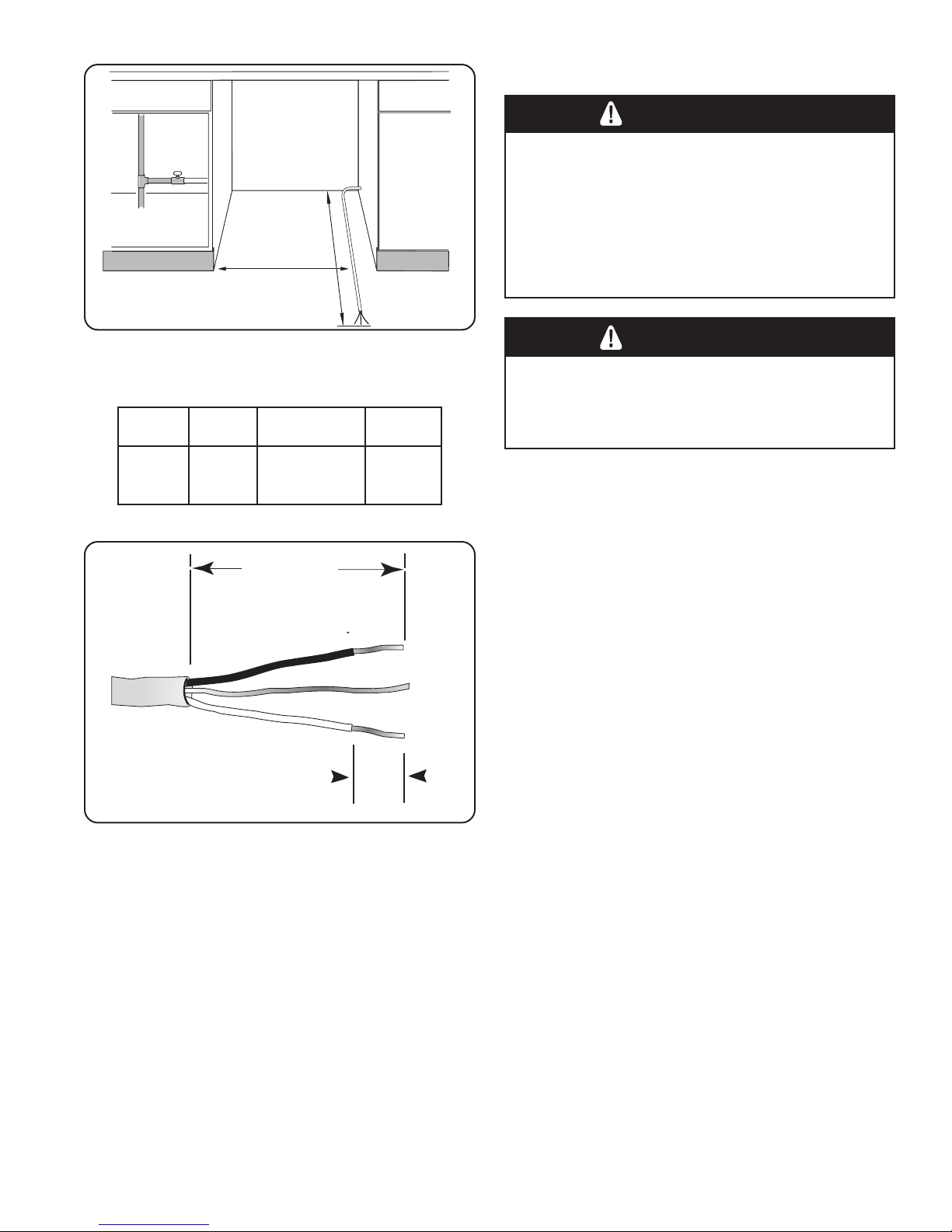
Electrical Preparation
ELECTRICAL PREPARATION
WARNING
Electrical Shock Hazard
To avoid electrical shock, do not work on an
energized circuit. Doing so could result in serious
injury or death. Only qualified electricians should
perform electrical work. Do not attempt any work
on the dishwasher electric supply circuit until you
are certain the circuit is
de-energized.
Figure 4
Dishwasher Electrical Rating
stloVztreHserepmAsttaW
0210651
Figure 5
WARNING
Fire Hazard
To avoid a fire hazard, make sure electrical work
is properly installed. Only qualified electricians
should perform electrical work.
054,1
)xam(
Electrical Supply
The customer has the responsibility of ensuring that the
dishwasher electrical installation is in compliance with all
national and local electrical codes and ordinances. The
dishwasher is designed for an electrical supply of 120V,
60 Hz, AC, connected to a dishwasher-dedicated,
properly grounded electrical circuit with a fuse or breaker
rated for 15 amps. Electrical supply conductors shall be a
minimum #14 AWG copper wire rated at 75°C or higher.
Regardless of where the electrical supply cable enters the
enclosure (following the guidelines on page 8), position
the cable 21” (533mm) from the enclosure’s left side, as
shown in Figure 4. Extend the cable 30” (762mm) from
the enclosure’s back, as shown in Figure 4.
Remove 3” - 4” (75mm - 100mm) of the cable’s outer
casing, as shown in Figure 5, then remove 3/8” - 1/2”
(9 - 13mm) of insulation from each wire, as shown in
Figure 5.
5
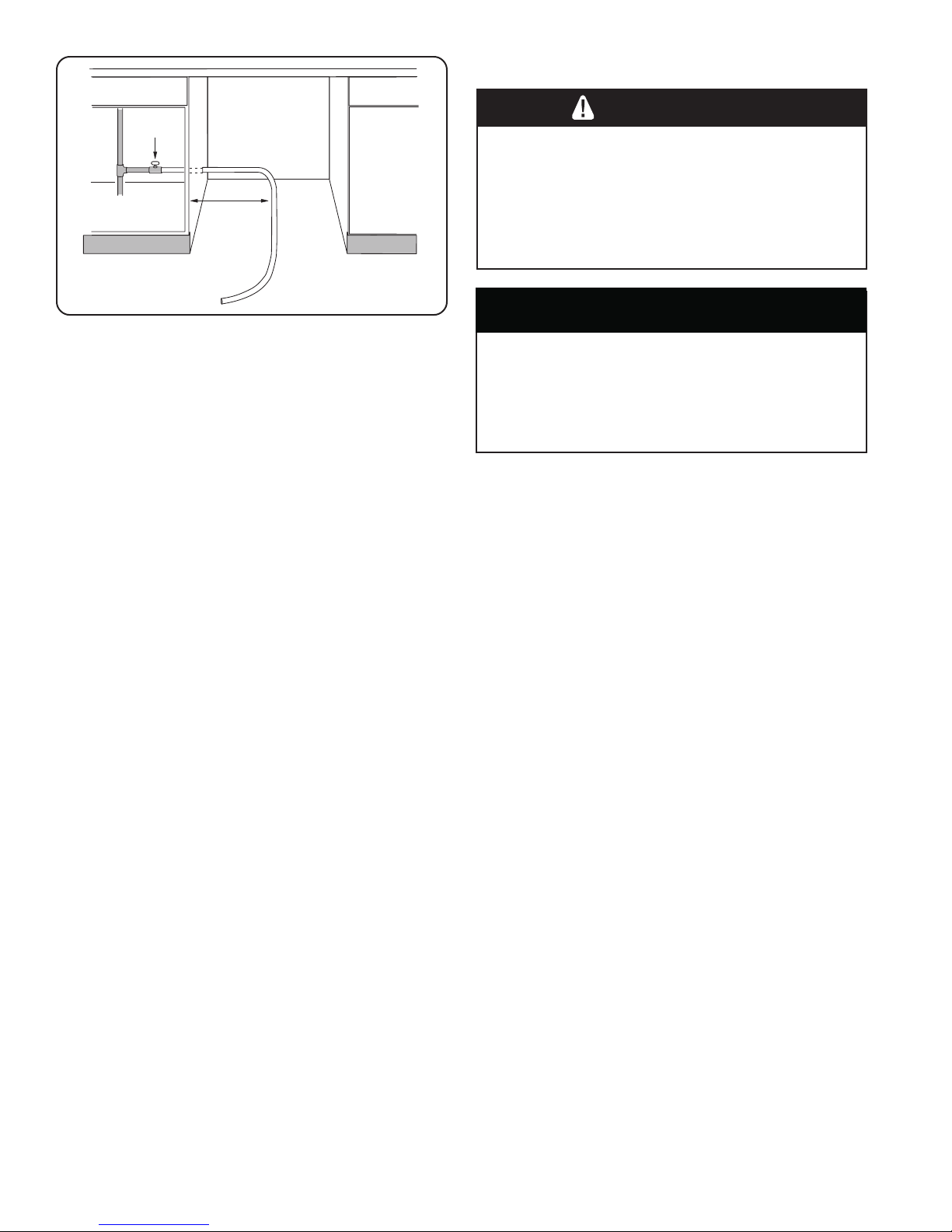
14"
(355mm)
Shut off
Valve
Hot Water
Supply
Line
Plumbing Preparation
PLUMBING PREPARATION
To avoid being scalded, do not perform any work
on a charged hot water line. Serious injury could
result. Only qualified plumbers should perform
plumbing work. Do not attempt any work on the
dishwasher hot water supply plumbing until you
are certain the hot water supply is shut off.
WARNING
Scald Hazard
Figure 6
CAUTION
Temperatures required for soldering and sweating
will damage the dishwasher’s base and water inlet
valve. If plumbing lines are to be soldered or
sweated, keep the heat source at least 6 inches
(152.4 mm) away from the dishwasher’s base and
water inlet valve.
Hot Water Supply
The hot water heater should be set to deliver
approximately 120° F (49° C) water to the dishwasher.
Water that is too hot can cause some detergents to lose
effectiveness. Lower water temperatures will increase run
times. The hot water supply pressure must be between
15 - 145 psi (1 - 10 bars).
Hot Water Supply Plumbing
Install an easily accessible shut-off valve (not supplied) in
the hot water supply line, as shown in Figure 6. All solder
connections must be made before the water line is
connected to the dishwasher’s water inlet valve. Water
may also be supplied to the dishwasher by using a
braided hose line. Check with your local plumbing supply
sources for the proper hose and 90° elbow fitting.
6
NOTE: Regardless of where the hot water supply line
enters the enclosure, position the line 14” (355mm) from
the enclosure’s left side, as shown in Figure 6.
NOTE: Decide whether braided hose or copper tubing will
be used for the hot water supply plumbing, and purchase
the correct type of hot water supply shut-off valve, 90°
elbow, and necessary fittings for the hot water supply
plumbing.
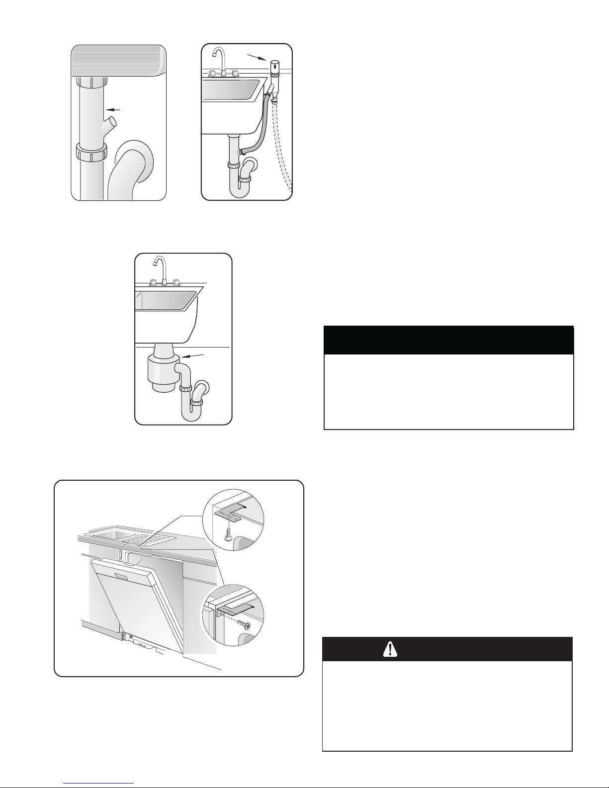
Plumbing Preparation/ Dishwasher Preparation
Y-branch
Tailpiece
Figure 7
Air Gap
Figure 8
PLUMBING PREPARATION (continued)
Drain Plumbing
Under Sink Drain Connection
If the dishwasher is to drain either directly into the
household drain plumbing or through an air gap, install a
y-branch tailpiece under the sink as shown in Figure 7.
Installing an Air Gap
If local ordinances require an air gap, as shown in
Figure 8, install it according to the manufacturer’s
instructions.
Disposer
Make sure to remove the disposer’s dishwasher drain
connection plug before connecting the dishwasher drain
hose. See Figure 9.
DISHWASHER PREPARATION
Dishwasher preparation involves four tasks:
• Installing the Mounting Brackets
• Removing the Toe Panel
• Installing the 90° elbow fitting
• Junction Box Preparation
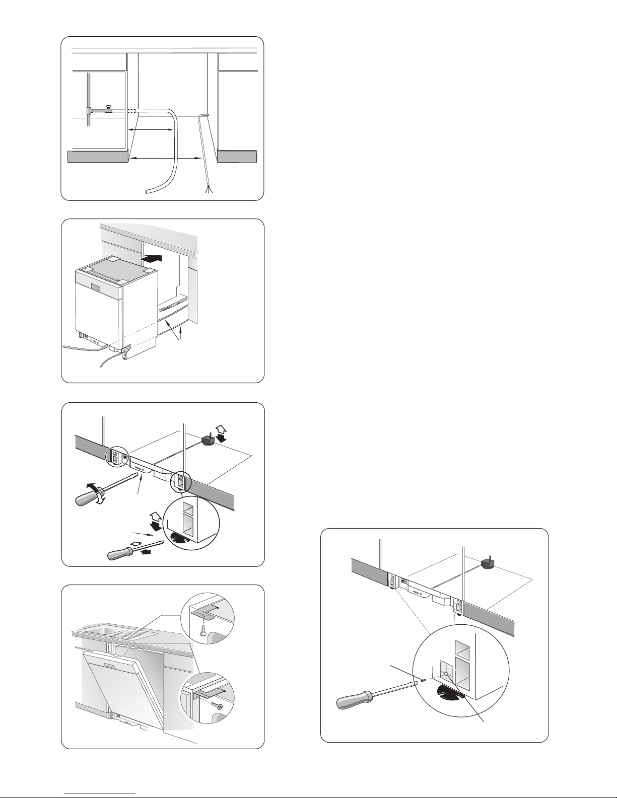
Installing the Countertop Mounting Brackets
Remove
plug
Figure 9
Top Mount
Side Mount
CAUTION
Before installing the supplied countertop mounting
brackets, decide which method of securing the
dishwasher into its enclosure will be used. Once
the mounting brackets are installed on the dishwasher, removing them is difficult and will damage
the mounting brackets and the dishwasher.
The dishwasher can be secured into its enclosure in two
ways:
1 Top Mount is used for countertops made of wood or
other materials that can easily drilled. Orient the
mounting brackets as shown in Figure 10, and
position the two small tabs on the mounting brackets
over the two slots on the dishwasher’s front corners.
Push the mounting brackets down firmly to insert the
tabs into the slots.
2 Side Mount is used for countertops made of marble,
granite, or other very hard materials that cannot be
easily drilled. Bend the mounting brackets along the
small holes and in the same direction as the two small
tabs. Orient the mounting brackets as shown in Figure
10, and position the two small tabs on the mounting
brackets over the two slots on the dishwasher’s front
corners. Push the mounting brackets down firmly to
insert the tabs into the slots.
Figure 10
WARNING
Tip Over Hazard
To avoid a tip over hazard, do not use the
dishwasher until it is completely installed. When
opening the door on an uninstalled dishwasher,
carefully open the door while supporting the rear
of the unit. Failure to follow this warning can
result in serious injury.
7
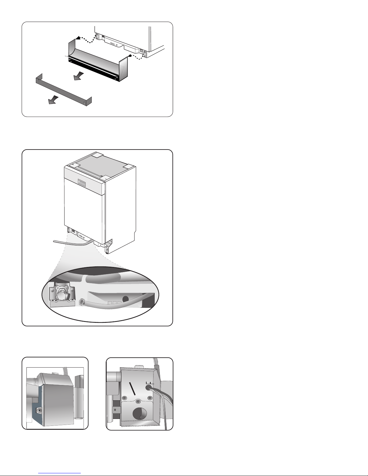
Figure 11
Toe
Plastic Base
Access Panel
Dishwasher Preparation
DISHWASHER PREPARATION (continued)
Removing the Toe Panel
Regular Toe Panel
The toe panel is loosely attached with tape. Remove the
tape and pull the toe panel away from the dishwasher. Set
the toe panel aside. It will be reinstalled later.
SHY66C and SHX99A Plastic Base Access Panel and
Toe Panel
The plastic base access panel (select models SHY66C/
SHX99A only) and toe panel are in place on the
dishwasher, but are not attached. Remove the toe panel
first, as shown in Figure 11, then remove the plastic
base access panel, as shown in Figure 11.
Installing the 90° Elbow Fitting
NOTE: The 90° elbow fitting is not supplied with the
dishwasher, and must be purchased separately. If the
dishwasher’s hot water supply line is to be copper tubing,
make certain the elbow has a compression fitting.
Apply Teflon tape or other pipe sealant when required.
Orient the hot water supply connection leg of the elbow
toward the channel opening in the dishwasher base. See
Figure 12.
Figure 12
Junction Box Preparation
1 Remove junction box cover (see Figure 13) by lifting
the junction box cover up and off.
2 Remove the strain relief plate by removing the screw
at the back of the junction box, as shown in Figure
14 and sliding the strain relief plate out.
3 Set the junction box cover, strain relief plate, and
screw aside. They will be reinstalled later.
Remove
Screw
Junction
Box
Cover
Figure 13
8
X
Figure 14
25”
(636 mm)
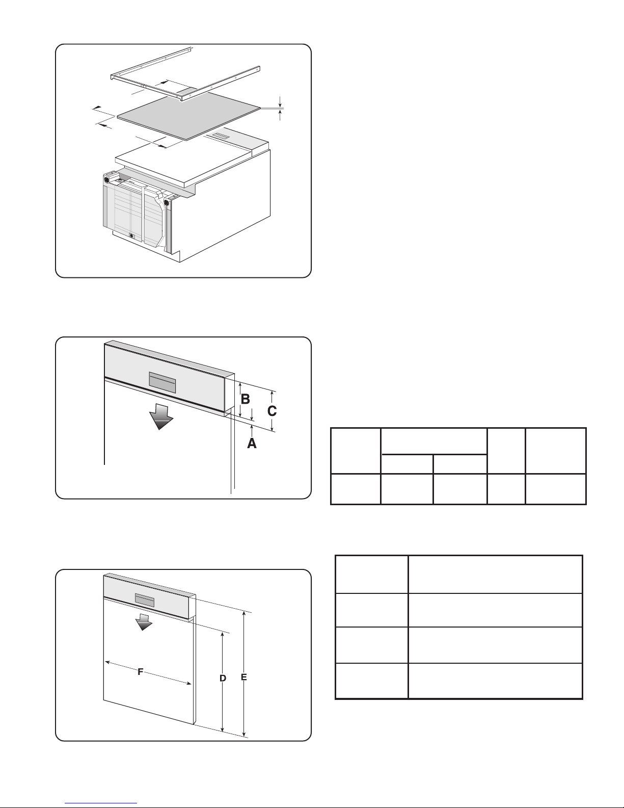
Door Panel Installation
1/4” max.
(6 mm)
DOOR PANEL INSTALLATION
SHU Models - Accessory Panel Installation
If you have an SHU model and have ordered an accessory panel kit, install the panel prior to sliding the dishwasher into place. The panel dimensions are shown in
Figure 15.
23-1/16”
(586 mm)
Figure 15
SHI Models - Panel Installation
SHI models come with additional mounting hardware and
a template sheet with installation instructions. The stainless steel models of the SHI series also come with two
extension pieces. The extension pieces are used to
match the control panel height (Figure 16, “B” dimension)
to the horizontal drawer line of the cabinets, and must be
installed as shown in on the template sheet. The standard
piece is used for drawer heights up to 6” (152mm); the
long piece is used for drawer heights greater than 6”
(152mm) but 6-7/16” (164mm) or less. If your drawers are
taller than 6-7/16”, you can either slide the extension
piece in as far as it will go, or remove it and fit the door
panel directly below the control panel.
SHI/SHV Models - Panel Installation
SHV models come with additional mounting hardware and
a template sheet that will show you how to mount the
panel. One side of the template shows how to mount a
one piece panel; the other side shows how to mount a two
piece panel. Decide which type of installation you want
before proceeding with the installation.
Figure 16
Fig. 16
Dimension
SHI Only
Fig. 17
Dimension
D (SHI)
E
(SHI & SHV)
F
(SHI & SHV)
Extension “A”
Max. - Min.
Standard
5/16 - 11/16”
(8-18mm)
Long
11/16 - 1 1/8”
(18 - 29mm)
Panel Dimension
20 11/16” - 25”
(526mm - 635mm)
27 3/16” - 30 5/16”
(690mm - 770mm)
23 3/16” - 23 3/8”
(589mm - 594mm)
“B” “C”
Max.-Min.
5 5/16”
(135mm)
5 5/8 - 6 7/16”
(143 - 164mm)
Figure 17
9
14"
(355mm)
21"
(533mm)
Figure 18
Placing the Dishwasher/ Securing the Dishwasher
PLACING THE DISHWASHER
1 Straighten and position the hot water supply line and
the electrical supply cable as shown in Figure 18 so
that they will align with their channels under the
dishwasher base.
2 Position the dishwasher close enough to the enclosure
so that you can run the dishwasher drain hose to the
under sink drain connection. Make certain that the hot
water supply line and the electrical supply cable are in
their channels under the dishwasher base, as shown in
Figure 19.
3 Slide the dishwasher into the opening making sure that
the hot water supply line and the electrical supply
cable stay in their proper channels.
4 Make sure the dishwasher is level. Adjust the rear
leveler by turning the center screw at the front of the
dishwasher, as shown in Figure 20a. Turning the screw
clockwise raises the rear of the dishwasher. Adjust the
front levelers by turning them with a screwdriver, as
shown in Figure 20b. Turning the levelers to the right
raises the dishwasher. If additional height is needed,
shims may be added under the leveler feet.
Figure 19
a
b
Figure 20
Top Mount
Hot Water Supply Line
and Electrical Supply
Cable Position in
Channels
SECURING THE DISHWASHER
1 Drive the mounting screws through the holes in the
mounting brackets as shown in Figure 21 for Top
Mount or Side Mount.
2 After the unit is installed in the enclosure, leveled and
secured, lock the two front leg levelers in place by
driving the enclosed leg leveler locking screws into
each screw boss located in front of the levelers. See
Figure 22.
3 Tighten screws until they are flush with the surface of
the bosses.
Side Mount
Figure 21
10
Leg
Leveler
Locking
Screw
Screw
Boss
Figure 22
Silver
Spring
Clamp
Gold
Screw
Clamp
Drain Hose Connection
Installation of the Rubber Drain Hose
Adaptor
1 Obtain the Rubber Drain Hose Adaptor and the two
hose clamps from the Dishwasher Installation Kit.
2 On one outside end of the Rubber Drain Hose Adapter
is a raised groove. Insert the drain hose into the end
without the raised groove. Be sure to fully insert the
drain hose.
3 Secure the connection with the Silver Spring Clamp.
4 Use the Gold Screw Clamp to attach the Rubber Drain
Hose Adaptor to the house plumbing.
Connecting the Drain Hose to the
Household Plumbing
The dishwasher drain hose may be connected to the drain
plumbing in one of four ways:
1 Directly to the under-sink dishwasher drain connection,
as shown in Figure 23.
2 Directly to a disposer dishwasher drain connection, as
shown in Figure 24.
3 To the under-sink dishwasher drain connection through
an air gap, as shown in Figure 25.
4 To a disposer dishwasher drain connection through an
air gap, as shown on Figure 26.
Figure 23 Figure 24
Figure 25 Figure 26
Information on installing air gaps and disposers can be
found in the Plumbing Preparation section of this
manual.
NOTE: If the dishwasher drain hose is to be connected to
a disposer dishwasher drain connection, remove the plug
from the disposer’s dishwasher drain connection.
Use the supplied Rubber Drain Hose Adaptor and Drain
Hose Clamps to connect the dishwasher drain hose to the
plumbing drain connection. Use the spring clamp to
secure the Rubber Drain Hose Adaptor to the dishwasher
drain hose. Use the screw clamp to secure the Rubber
Drain Hose Adaptor to the plumbing drain connection.
The dishwasher drain hose must have one place along its
length that is securely attached 20 inches above the
cabinet floor.
11

Hot Water Connection
HOT WATER CONNECTION
To avoid being scalded, do not perform any work
on a charged hot water line. Serious injury could
result. Only qualified plumbers should perform
plumbing work. Do not attempt any work on the
dishwasher hot water supply plumbing until you
are certain the hot water supply is shut off.
NOTE: Make certain that the correct 90° elbow fitting (not
supplied) for the hot water supply line has been purchased and installed on the dishwasher as described in
the Dishwasher Preparation section of this manual.
The hot water supply line may be connected to the
dishwasher in one of two ways:
1 With braided hose.
2 With copper tubing.
Braided Dishwasher Supply Hose
After connections are made turn on the hot water supply
to check for leaks.
NOTE: Braided dishwasher supply hoses can also be
used to extend pre-existing dishwasher water supply
lines.
WARNING
Scald Hazard
Copper Tubing
CAUTION
Temperatures required for soldering and sweating
will damage the dishwasher’s water inlet valve. If
plumbing lines are to be soldered or sweated,
keep the heat source at least 6 inches (152.4 mm)
away from the dishwasher’s water inlet valve.
• If using a solder joint instead of a compression fitting,
be sure to make all solder connections before
connecting the water line to the dishwasher.
• Make certain there are no sharp bends or kinks in the
water line that might restrict water flow.
• Be sure to use pipe thread compound or Teflon tape to
seal the connection when required.
• Before connecting the copper hot water supply line to
the dishwasher, flush it with hot water to clear any
foreign material.
• Turn on the water supply to check for leaks after
making connections.
NOTE: Do not use pipe sealant on compression fittings.
12
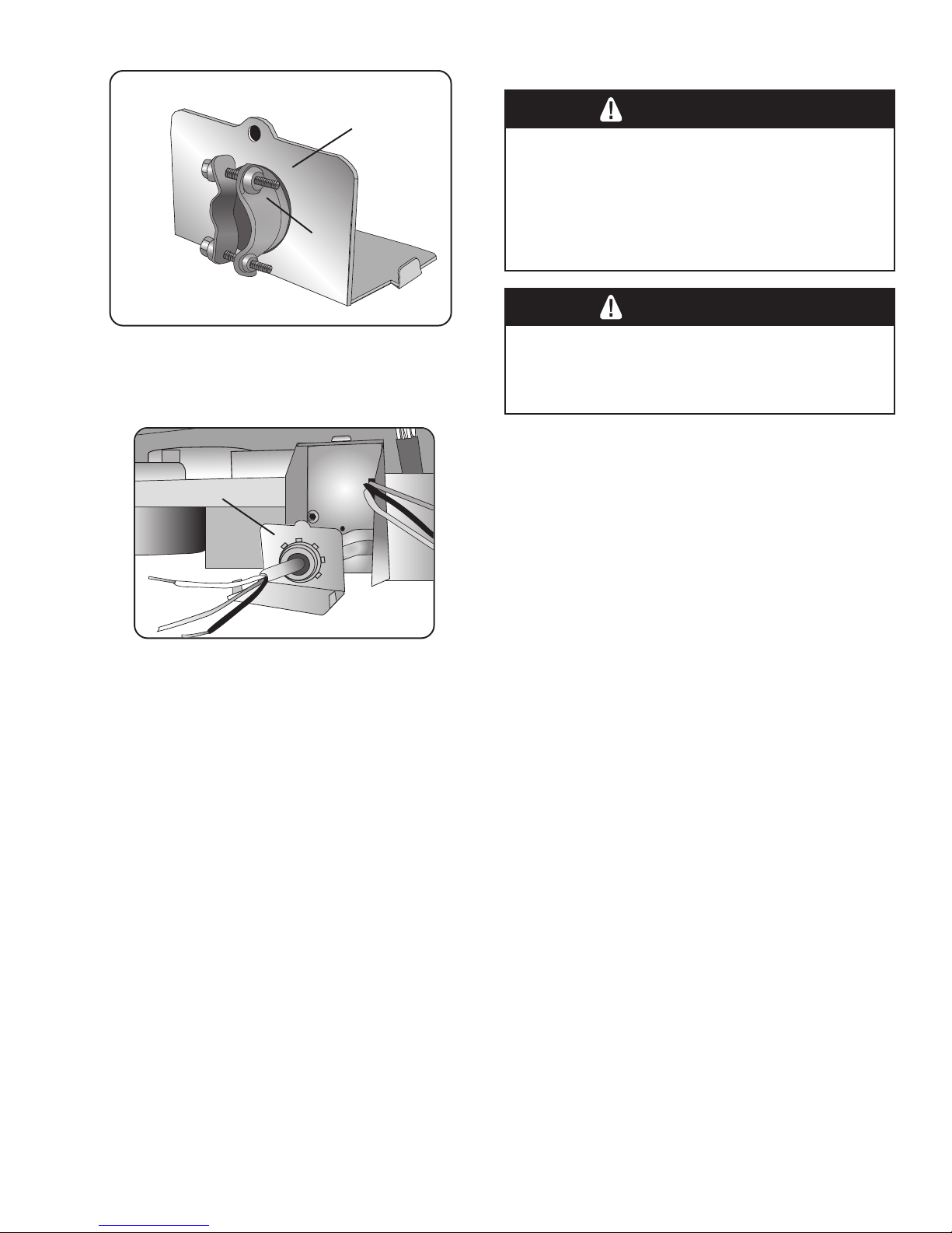
Electrical Connection
ELECTRICAL CONNECTION
Figure 27
Strain Relief Plate
Figure 28
Strain
Relief
Plate
Strain Relief
(not supplied)
WARNING
Electrical Shock Hazard
To avoid electrical shock, do not work on an
energized circuit. Doing so could result in serious
injury or death. Only qualified electricians should
perform electrical work. Do not attempt any work
on the dishwasher electric supply circuit until you
are certain the circuit is de-energized.
WARNING
Fire Hazard
To avoid a fire hazard, make sure electrical work
is properly installed. Only qualified electricians
should perform electrical work.
Grounding Instructions
The dishwasher must be properly grounded before
operating. This appliance must be connected to a
grounded metal permanent wiring system, or an
equipment grounding conductor must be run with the
circuit conductors and connected to the equipment
grounding terminal or lead on the dishwasher. Make sure
that the dishwasher is connected to a suitable ground in
compliance with all local codes or, in the absence of a
local code, with the NATIONAL ELECTRICAL CODE in
the United States or the CANADIAN ELECTRIC CODE
C22.1- latest edition in Canada as well as any provincial/
state or municipal or local codes that apply.
1 Retrieve the strain relief plate, and install a strain relief
(not supplied) into the opening on the strain relief plate.
NOTE: Orient the strain relief as shown in Figure 27.
2 Pass the electrical supply cable through the strain
relief, as shown in Figure 28. Leave 3 - 4 inches of
insulated wire extending through the strain relief plate.
3 Tighten the strain relief screws.
4 Slide the strain relief plate into the junction box, and
secure it to the junction box with the supplied screw.
13
 Loading...