


ISW-D8125CW-V2
Installation and Operation Guide
Inovonics Echostream
EN Interface Module

ISW-D8125CW-V2 | Installation and Operation Guide | Contents |
|
|
Contents |
|
|
1.0 |
Overview ............................................................................................................................................................... |
3 |
1.1 |
FCC Compliance Notice, Part 15......................................................................................................................... |
3 |
1.2 |
Features ................................................................................................................................................................... |
3 |
1.3 |
Specifications .......................................................................................................................................................... |
4 |
1.4 |
Power....................................................................................................................................................................... |
4 |
1.5 |
System Supervision ................................................................................................................................................ |
4 |
1.6 |
ISW-D8125CW-V2 Back View ............................................................................................................................ |
4 |
2.0 |
Installation............................................................................................................................................................. |
5 |
2.1 |
Configuring the Commercial Wireless Interface Module.................................................................................. |
5 |
2.2 |
Mounting the Commercial Wireless Interface Module ..................................................................................... |
5 |
2.3 |
Wiring the Commercial Wireless Interface Module to the Control Panel and EN4200 Serial Receiver .... |
6 |
3.0 |
Operation .............................................................................................................................................................. |
9 |
3.1 |
Commercial Wireless Interface Module Quick Startup Recommendations ................................................... |
9 |
3.2 |
Labeling the Bosch Transmitters .......................................................................................................................... |
9 |
3.3 |
Keypad Overview .................................................................................................................................................. |
9 |
3.4 |
Initial Power-up .................................................................................................................................................... |
10 |
3.5 |
RF System OK ..................................................................................................................................................... |
10 |
3.6 |
Call for Service..................................................................................................................................................... |
10 |
3.7 |
Factory Default Passcode .................................................................................................................................... |
10 |
3.8 |
Entering Invalid Passcodes.................................................................................................................................. |
10 |
3.9 |
Keypad Menus ..................................................................................................................................................... |
11 |
3.10 |
Other Programming Functions........................................................................................................................... |
15 |
4.0 |
Troubleshooting................................................................................................................................................. |
17 |
4.1 |
Troubleshooting Solutions .................................................................................................................................. |
17 |
4.2 |
EN4200 Receiver Supervision ............................................................................................................................ |
19 |
4.3 |
Missing RF Transmitters ..................................................................................................................................... |
19 |
4.4 |
Low Transmitter Battery Conditions ................................................................................................................. |
19 |
4.5 |
Commercial Wireless Interface Module Power Cycle Operation .................................................................. |
19 |
4.6 |
Frequently Asked Questions ............................................................................................................................... |
19 |
5.0 |
Program Record Sheet ..................................................................................................................................... |
21 |
2 |
Bosch Security Systems, Inc. | 8/11 | F01U161691-05 |

ISW-D8125CW-V2 | Installation and Operation Guide | Overview
1.0 Overview
The ISW-D8125CW-V2 is an integrated commercial wireless interface module and keypad. The keypad accesses the programming and diagnostic functions of the wireless portion of the system. The integrated keypad on the commercial wireless interface module looks different from the typical keypads (D1255, D1256, D1257, and so on) so that it is not mistaken for a system keypad.
The commercial wireless interface module must be mounted within 5 ft of the control panel. It is designed so that it is mounted right next to the D8103, D8108A or D8109 enclosure.
The commercial wireless interface module is compatible with the following control panels:
•GV3 Series: D9412GV3, D7412GV3, D7212GV3
•GV2 Series: D9412GV2, D7412GV2, D7212GV2
•G Series: D9412G, D7412G, D7212G*
•9000 Series: D9412, D9112*, D7412, D7212*
*These control panels must have Firmware 6.5 or later installed (Firmware 6.51 or later for the D7212G).
All of the compatible control panels can have both hardwired (D8128D OctoPOPITS, D8125 Popex / D9127 POPITS, D8125MUX) and wireless points connected at the same time.
To add wireless points, an Inovonics Echostream EN4200 Serial Receiver must be connected to the commercial wireless interface module which is then connected to the control panel’s ZONEX 1 (and/or ZONEX 2) terminals and Aux Power. For best transmitter reception results, the EN4200 Serial Receiver should be centrally located among the transmitters. If transmitters are at too great of a distance for the EN4200 Receiver to pick up the transmission, install an EN5040-T RF Repeater.
1.1FCC Compliance Notice, Part 15
This equipment has been tested and found to comply with the limits for a Class B digital device, pursuant to Part 15 of the FCC Rules. These limits are designed to provide reasonable protection against harmful interference in a commercial installation. This equipment generates, uses, and can radiate radio frequency energy, and, if not installed in accordance with the instructions, may cause harmful interference to radio communications. However, there is no guarantee that interference will not occur in a particular installation. If this equipment does cause harmful interference to radio or television reception, which can be determined by turning the equipment on and off, the user is encouraged to try to correct the interference by one or more of the following measures:
1.Reorient or relocate the receiving antenna.
2.Increase the separation between the equipment and the receiver.
3.Connect the equipment into an outlet on a circuit different from that to which the receiver is connected.
4.Consult the dealer or an experienced radio/TV technician for help.
1.2Features
•The commercial wireless interface module features a menu-driven user interface.
•The commercial wireless interface module supports the following number of Bosch commercial wireless transmitters:
-234 transmitters (117 per bus) on the D9112 and all versions of the D9412
-65 transmitters on all versions of the D7412
-32 transmitters on all versions of the D7212
Points 74 and 75 on ZONEX 1 and Points 194 and 195 on ZONEX 2 cannot be used for any device other than the ISW-EN1224-ON Keyfob.
•The commercial wireless interface module provides diagnostic functions to troubleshoot RF transmitters.
•The commercial wireless interface module features a fixed device check-in time of 3 minutes.
•The commercial wireless interface module features a programmable system supervision interval.
Bosch Security Systems, Inc. | 8/11 | F01U161691-05 |
3 |

ISW-D8125CW-V2 | Installation and Operation Guide | Overview
1.3Specifications
Table 1: Commercial Wireless Interface
Module Specifications
|
|
Specification |
Value |
|
|
User Interface |
- LCD Display: 2 lines x 16 |
|
characters, backlit |
|
- Keypad: 0-9 numbers; ESC, ENT, |
|
PREV, NEXT and DIAG keys |
Operating |
10.2 - 14 VDC supplied by Aux Power |
Voltage |
from Control Panel or an External |
|
Auxiliary Power Supply. |
Current |
20 mA typical, 50 mA maximum |
|
plus ≈ 60 mA for each EN4200 receiver |
Operating |
+32°F to +149°F (0°C to +65°C), 93% |
Temperature |
Relative Humidity |
|
|
Wiring |
18 AWG or 22 AWG Solid or Stranded. |
|
Maximum distance from the control |
|
panel to the commercial wireless |
|
interface module cannot exceed 5 ft (1.5 |
|
m). |
|
Maximum distance from |
|
commercial wireless interface module to |
|
EN4200 cannot exceed 100 ft (33 m). |
Dimensions |
3.94 in. x 6.5 in. x 1.2 in. |
(HxWxD) |
(10 cm x 16.6 cm x 3 cm) |
|
|
For UL Listed installations, install the commercial wireless interface module within 20 ft (6 m) of, and within the same room as, the EN4200 Serial Receiver.
1.4Power
If the commercial wireless interface module is powered down and then back up, it may take up to a maximum of 5 minutes (Check-In Time is fixed at 3 minutes) for all the transmitters to report back to the commercial wireless interface module with their current status.
In addition, when the commercial wireless interface module is powered up, all programmed RF points will report Normal until their state is updated.
The commercial wireless interface module’s power should be connected to the control panel using the Aux Power terminals. If the commercial wireless interface module were to lose power, the following conditions may result:
•All RF points will report to the control panel as missing (trouble/alarm).
•All RF points will initialize in a normal state when power is reapplied.
•Alarms initiated prior to power loss would be reset. If the alarm conditions persist when power is restored, new alarms would be generated.
Programmed settings such as RF point configuration will remain intact upon the event of a power loss.
1.5System Supervision
1.5.1Watchdog
The commercial wireless interface module implements a watchdog software. Failure of the program will result in a software reset within two seconds. This may cause a trouble condition on the control panel for the duration of the reset.
1.5.2Self-Testing
The commercial wireless interface module EEPROM memory is automatically tested on a periodic basis. The EEPROM checksum is verified every ten minutes. If the EEPROM checksum fails, a point bus trouble condition will be seen at the control panel.
1.6ISW-D8125CW-V2 Back View
Refer to Figure 1 for an overview of the ISW-D8125CW-V2 printed circuit board.
Figure 1: ISW-D8125CW-V2 Back View
8
1
2
7
3
4
6 |
5 |
1 - Status LEDs (TX1, RX1, TX2, and RX2)
2 ZONEX BUS Terminals
3 RECEIVER 1 Terminals
4RECEIVER 2 Terminals
5 Receiver (RCV) Selection Jumpers
6Tamper Switch
7LCD Contrast Adjustment
8Built-in Sounder (indicates valid and invalid keypad entries)
4 |
Bosch Security Systems, Inc. | 8/11 | F01U161691-05 |

ISW-D8125CW-V2 | Installation and Operation Guide | Installation
2.0 Installation
The commercial wireless interface module is packaged with a Point Label Sheet. Save these, as you will use them when identifying the point numbers on the Bosch transmitters.
2.1Configuring the Commercial Wireless Interface Module
2.1.1Register (REG) Pins
By default, the commercial wireless interface module is configured to register RF transmitters with a single press of the transmitter’s reset button.
You can also configure the commercial wireless interface module to require two presses of the RF transmitter’s reset button to register the RF transmitter.
Refer to Figure 2 to set the REG pins.
Figure 2: Register (REG) Pins Settings
P2 P1
11
1
2 2 REG RCV
P2 P1
11
2 |
|
2 |
2 |
|
REG RCV |
1 - Single-press setting (default configuration)
2Double-press setting
2.1.2Receiver (RCV) Pins
If you set the RCV jumper on the commercial wireless interface module to 1 or remove the jumper plug from the RCV pins, you can use only one receiver and it must be connected to the Receiver 1 terminals on the commercial wireless interface module. Refer to Figure 1 on page 4 for the location of the RCV jumper.
The commercial wireless interface module supports up to two ISW-EN4200 Receivers.
By default, the commercial wireless interface module supports one receiver. Refer to Figure 3 to set the RCV pins.
Figure 3: Receiver (RCV) Pins Settings
P2 P1
11
1
2 2 REG RCV
P2 P1
11
|
2 |
2 |
2 |
|
REG RCV |
1 - Setting for one receiver (default configuration)
2Setting for two receivers
2.2Mounting the Commercial Wireless Interface Module
1.Select the knockout from the control panel enclosure that will be used to route the wiring.
Figure 4: Enclosure Knockout Options
Wire |
Knockouts |
D8103 Enclosure shown.
2.Select the location from which the commercial wireless interface module’s wiring will be routed.
3.Remove the base of the commercial wireless interface module.
Bosch Security Systems, Inc. | 8/11 | F01U161691-05 |
5 |

ISW-D8125CW-V2 | Installation and Operation Guide | Installation
4.Connect the wiring (refer to Figure 6 on page 7, or Figure 7 on page 8) to the commercial wireless interface module and mount the cover unit to the base.
Figure 5: ISW-D8125CW-V2 Mounting Options
1 |
2 |
3
2
1
1 - Four-screw mounting holes
(for mounting on an electrical box)
2Two-screw mounting holes
(for mounting on an electrical box or in control panel enclosure)
3Wire routing openings
2.3Wiring the Commercial Wireless Interface Module to the Control Panel and EN4200 Serial Receiver
For best transmitter reception results, place the EN4200 Serial Receiver in a central location among the transmitters. If transmitters are too far away for the receiver to pick up the transmission, install an ISW-EN5040-T Commercial Wireless RF Repeater.
Certain installation configurations may require a second EN4200 Receiver.
Refer to Figure 6 on page 7, and Figure 7 on page 8, for proper wiring connections.
Disconnect all power to the control panel and to the commercial wireless interface module before starting any work with the internal components.
For UL Listed installations, install the commercial wireless interface module within 20 ft (6 m) of, and within the same room as, the EN4200 Serial Receiver.
The maximum distance from the control panel to the commercial wireless interface module cannot exceed 5 ft
(1.5 m).
6 |
Bosch Security Systems, Inc. | 8/11 | F01U161691-05 |
ISW-D8125CW-V2 | Installation and Operation Guide | Installation
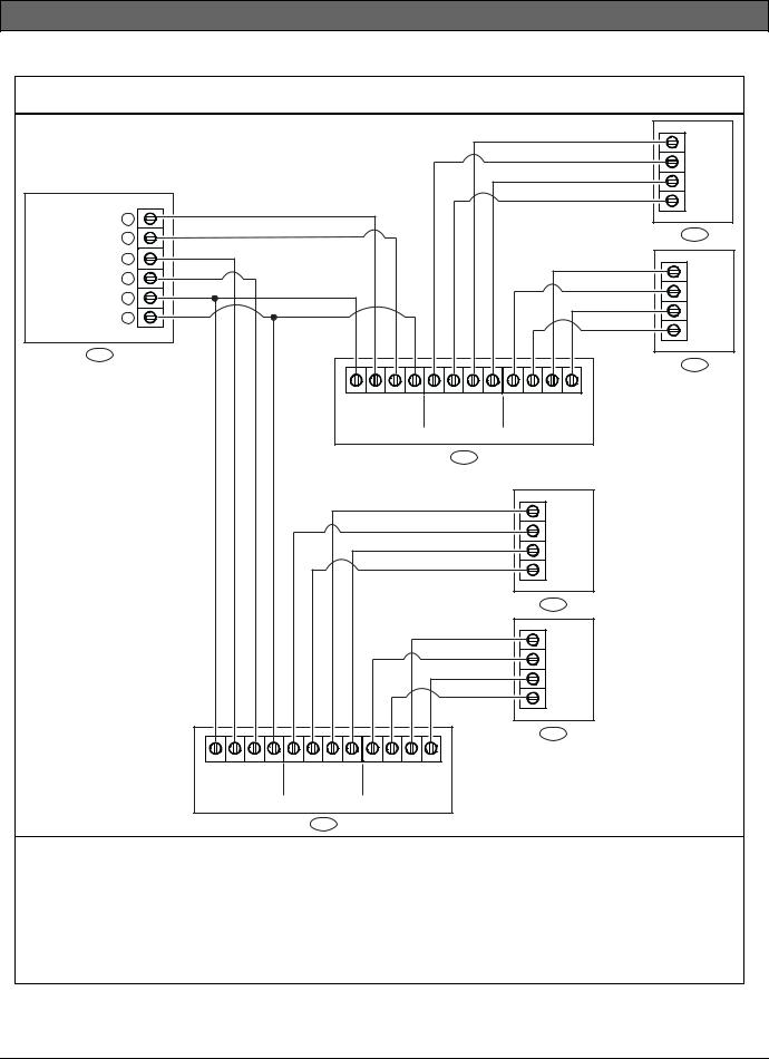
Figure 6: ISW-D8125CW-V2 to D9412 (GV3, GV2, and G) and D9112 Control Panel Wiring Diagram
ZONEX OUT 1 28 ZONEX IN 1 27
ZONEX OUT 2 26
ZONEX IN 2 25 ZONEX POWER + 24
ZONEX COMMON 23
3
|
|
|
|
|
|
|
|
|
|
|
|
TX |
|
|
|
|
|
|
|
|
|
|
|
|
Vs |
|
|
|
|
|
|
|
|
|
|
|
|
GND |
|
|
|
|
|
|
|
|
|
|
|
|
RX |
|
|
|
|
|
|
|
|
|
|
|
|
4 |
|
|
|
|
|
|
|
|
|
|
|
|
TX |
|
|
|
|
|
|
|
|
|
|
|
|
Vs |
|
|
|
|
|
|
|
|
|
|
|
|
GND |
|
|
|
|
|
|
|
|
|
|
|
|
RX |
|
|
|
|
|
|
|
|
|
|
|
|
5 |
|
|
|
|
+12V |
IN OUT GND |
+12V |
TX1 RX1 |
GND |
+12V |
TX2 |
RX2 |
GND |
|
|
|
|
ZONEX BUS |
RECEIVER 1 |
RECEIVER 2 |
||||||
|
|
|
|
|
|
|
1 |
|
|
|
|
|
|
|
|
|
|
|
|
|
|
|
|
TX |
|
|
|
|
|
|
|
|
|
|
|
|
Vs |
|
|
|
|
|
|
|
|
|
|
|
|
GND |
|
|
|
|
|
|
|
|
|
|
|
|
RX |
|
|
|
|
|
|
|
|
|
|
|
|
6 |
|
|
|
|
|
|
|
|
|
|
|
|
TX |
|
|
|
|
|
|
|
|
|
|
|
|
Vs |
|
|
|
|
|
|
|
|
|
|
|
|
GND |
|
|
|
|
|
|
|
|
|
|
|
|
RX |
|
|
|
|
|
|
|
|
|
|
|
|
7 |
|
+12V IN OUT GND |
+12V |
TX1 |
RX1 |
GND |
+12V TX2 RX2 |
GND |
|
|
|
|
|
|
ZONEX BUS |
RECEIVER 1 |
RECEIVER 2 |
|
|
|
|
|
|
||||
|
|
|
2 |
|
|
|
|
|
|
|
|
|
1- ISW-D8125CW-V2 connected to Zonex 1 on control panel (Points 9-127) 2- ISW-D8125CW-V2 connected to Zonex 2 on control panel (Points 129-247) 3- Control Panel
4- EN4200 Receiver (RECEIVER 1 on first ISW-D8125CW-V2) 5- EN4200 Receiver (RECEIVER 2 on first ISW-D8125CW-V2)
6- EN4200 Receiver (RECEIVER 1 on second ISW-D8125CW-V2) 7- EN4200 Receiver (RECEIVER 2 on second ISW-D8125CW-V2)
Bosch Security Systems, Inc. | 8/11 | F01U161691-05 |
7 |

ISW-D8125CW-V2 | Installation and Operation Guide | Installation
Figure 7: ISW-D8125CW-V2 to D7412 and D7212 (GV3, GV2, and G) Control Panel Wiring Diagram |
||||
|
|
|
|
TX |
|
|
|
|
Vs |
|
2 |
|
|
GND |
|
|
|
|
RX |
ZONEX OUT 1 28 |
|
|
|
|
|
ZONEX IN 1 27 |
|
|
3 |
|
NOT USED 26 |
|
|
|
|
NOT USED 25 |
|
|
TX |
|
|
|
|
|
ZONEX POWER + 24 |
|
|
Vs |
|
|
|
|
||
ZONEX COMMON 23 |
|
|
GND |
|
|
|
|
||
|
|
|
|
RX |
|
|
|
|
4 |
|
+12V IN OUT GND |
+12V TX1 RX1 GND |
+12V TX2 RX2 |
GND |
|
ZONEX BUS |
RECEIVER 1 |
RECEIVER 2 |
|
|
|
1 |
|
|
1- ISW-D8125CW-V2 connected to Zonex 1 on control panel (Points 9-127) |
|
|||
|
(D7412: Points 9-75; D7212: Points 9-40) |
|
|
|
2- |
Control Panel |
|
|
|
3- EN4200 Receiver (RECEIVER 1 on ISW-D8125CW-V2) |
|
|
||
4- EN4200 Receiver (RECEIVER 2 on ISW-D8125CW-V2) |
|
|
||
8 |
Bosch Security Systems, Inc. | 8/11 | F01U161691-05 |
 Loading...