


INTEGRUS
Bosch INTEGRUS, LBB 4502/04, LBB 4502/08, LBB 4502/16, LBB 4502/32 Installation And Operating Manual
...
INTEGRUS
DIGITAL INFRA-RED
LANGUAGE DISTRIBUTION SYSTEM
Installation and Operating Manual
BOSCH

2 | en INTEGRUS | Digital Infra-red Language Distribution System
BOSCH Security Systems B.V.| February 2003
© 2003 BOSCH Security Systems GmbH

INTEGRUS | Digital Infra-red Language Distribution System en | 3
BOSCH Security Systems | February 2003
Table of contents
1
System description and planning ............................................................................................................................... 5
1.1 System overview .......................................................................................................................................................................................... 5
1.2 System technology....................................................................................................................................................................................... 7
1.2.1 IR radiation...................................................................................................................................................................................... 7
1.2.2 Signal Processing ............................................................................................................................................................................ 7
1.2.3 Quality modes ................................................................................................................................................................................. 8
1.2.4 Carriers and channels..................................................................................................................................................................... 8
1.3 Aspects of infra-red distribution systems................................................................................................................................................ 9
1.3.1 Directional sensitivity of the receiver ......................................................................................................................................... 9
1.3.2 The footprint of the radiator........................................................................................................................................................ 9
1.3.3 Ambient lighting........................................................................................................................................................................... 10
1.3.4 Objects, surfaces and reflections ............................................................................................................................................... 10
1.3.5 Positioning the radiators .............................................................................................................................................................11
1.3.6 Overlapping footprints and multipath effects......................................................................................................................... 13
1.4 Planning an Integrus infra-red radiation system .................................................................................................................................. 13
1.4.1 Rectangular footprints ................................................................................................................................................................. 13
1.4.2 Planning radiators......................................................................................................................................................................... 14
1.4.3 Cabling 15
1.5 Setting the radiator delay switches.......................................................................................................................................................... 16
1.5.1 System with one transmitter ....................................................................................................................................................... 16
1.5.1.1 Determining delay switch positions by measuring the cable lengths ................................................................. 16
1.5.1.2 Determining delay switch positions by using a delay measuring tool ................................................................ 17
1.5.2 System with two or more transmitters in one room ..............................................................................................................18
1.5.3 System with more than 4 carriers and a radiator under a balcony....................................................................................... 20
1.6 Testing the coverage area......................................................................................................................................................................... 21
2 Infra-Red Transmitters (LBB 4502/xx) ................................................................................................................... 22
2.1 Description ................................................................................................................................................................................................. 22
2.2 Audio interface modules .......................................................................................................................................................................... 24
2.2.1 DCN Interface Module (LBB 3423/00) .................................................................................................................................. 24
2.2.2 Mounting an interface module in the transmitter housing ...................................................................................................25
2.3 Connections................................................................................................................................................................................................ 27
2.3.1 Connecting the DCN system ..................................................................................................................................................... 27
2.3.2 Connecting other external audio sources................................................................................................................................. 28
2.3.3 Connecting an emergency signal ............................................................................................................................................... 29
2.3.4 Connecting to another transmitter............................................................................................................................................ 30
2.4 Using the configuration menu ................................................................................................................................................................ 31
2.4.1 Overview........................................................................................................................................................................................ 31
2.4.2 Navigate through the menu........................................................................................................................................................ 32
2.4.3 Examples........................................................................................................................................................................................ 33
2.5 Configuration and operation ................................................................................................................................................................... 36
2.5.1 Start-up 36
2.5.2 Main menu ..................................................................................................................................................................................... 36
2.5.3 View transmitter status................................................................................................................................................................ 36
2.5.4 View fault status ........................................................................................................................................................................... 37
2.5.5 Set monitoring options................................................................................................................................................................ 37
2.5.6 View version information ........................................................................................................................................................... 37
2.5.7 Set transmission mode................................................................................................................................................................. 38
2.5.8 Set number of channels............................................................................................................................................................... 38
2.5.9 Set channel quality and assign inputs to channels .................................................................................................................. 38

4 | en INTEGRUS | Digital Infra-red Language Distribution System
BOSCH Security Systems B.V.| February 2003
2.5.10 Set channel names ........................................................................................................................................................................ 39
2.5.11 Disable or enable carriers............................................................................................................................................................ 40
2.5.12 View carrier assignments............................................................................................................................................................. 40
2.5.13 Configure auxiliary inputs ........................................................................................................................................................... 41
2.5.14 Set sensitivity of the inputs......................................................................................................................................................... 41
2.5.15 Choose transmitter name............................................................................................................................................................ 41
2.5.16 Enable / disable IR-monitoring ................................................................................................................................................ 42
2.5.17 Enable / disable headphone output ......................................................................................................................................... 42
2.5.18 Reset all options to factory default values ............................................................................................................................... 42
3 Infra-red Radiators (LBB 4511/00 and LBB 4512/00).............................................................................................. 43
3.1 Description ................................................................................................................................................................................................. 43
3.2 Radiator status indication......................................................................................................................................................................... 44
3.3 Mounting the radiators ............................................................................................................................................................................. 44
3.4 Connecting radiators to the transmitter ................................................................................................................................................ 47
3.5 Using the output power selection switch .............................................................................................................................................. 47
4 Infra-Red Receivers (LBB 4540/xx)......................................................................................................................... 48
4.1 Description ................................................................................................................................................................................................. 48
4.2 Operation .................................................................................................................................................................................................... 49
4.3 Reception test mode ................................................................................................................................................................................. 49
4.4 Receiver headphones ................................................................................................................................................................................ 49
5 Charging Units (LBB 4560/xx)................................................................................................................................ 50
5.1 Description ................................................................................................................................................................................................. 50
5.2 Wall mounting the charging cabinet ...................................................................................................................................................... 51
5.3 Charging procedure................................................................................................................................................................................... 51
6 Troubleshooting....................................................................................................................................................... 52
7 Technical Data......................................................................................................................................................... 53
7.1 System Specification ................................................................................................................................................................................. 53
7.2 Transmitters and Modules .......................................................................................................................................................................54
7.2.1 LBB 4502/xx Infra Red Transmitters ...................................................................................................................................... 54
7.2.2 LBB 3423/00 DCN Interface Module ..................................................................................................................................... 54
7.3 Radiators and Accessories........................................................................................................................................................................ 55
7.3.1 LBB 4511/00 and LBB 4512/00 Radiators............................................................................................................................. 55
7.3.2 LBB 3414/00 Wall Mounting Bracket ..................................................................................................................................... 55
7.4 Receivers, Battery Packs and Charging Units....................................................................................................................................... 56
7.4.1 LBB 4540 Pocket Receivers ....................................................................................................................................................... 56
7.4.2 LBB 4550/00 NiMH Battery Pack ...........................................................................................................................................56
7.4.3 LBB 4560 Charging Units........................................................................................................................................................... 56
7.5 Connection details .....................................................................................................................................................................................57
7.5.1 Mains cables .................................................................................................................................................................................. 57
7.5.2 Audio cables .................................................................................................................................................................................. 57
7.5.3 Earphones...................................................................................................................................................................................... 57
7.5.4 Emergency switch ........................................................................................................................................................................ 57
7.6 Guaranteed rectangular footprints ......................................................................................................................................................... 58
Product index ................................................................................................................................................................ 60
INTEGRUS | Digital Infra-red Language Distribution System en | 5
BOSCH Security Systems | February 2003
1 System description and planning
1.1 System overview
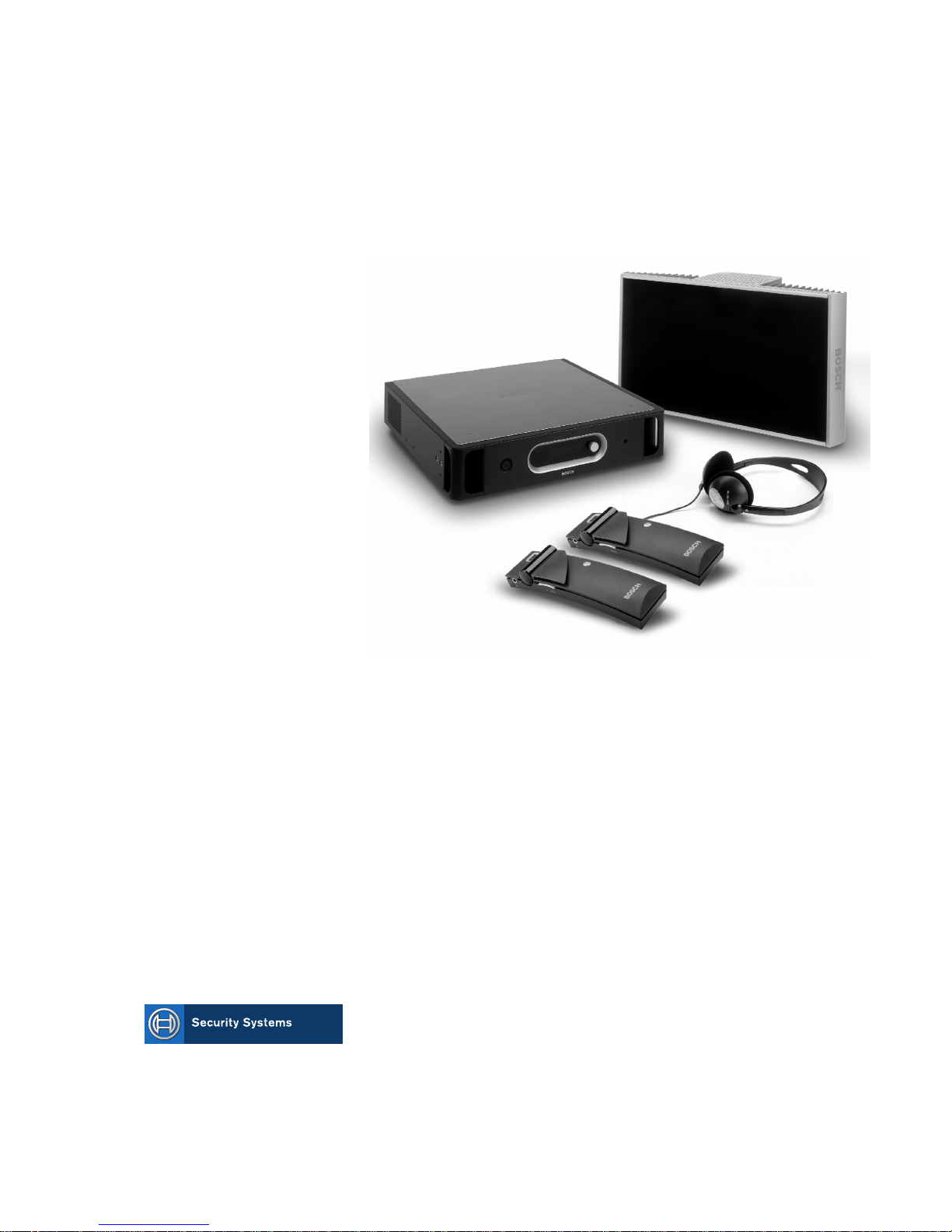
Integrus is a system for wireless distribution of audio signals via infra-red radiation. It can be used in a simultaneous
interpretation system for international conferences where multiple languages are used. To enable all participants to understand
the proceedings, interpreters simultaneously translate the speaker’s language as required. These interpretations are distributed
throughout the conference venue, and delegates select the language of their choice and listen to it through headphones.
The Integrus system can also be used for music distribution (mono as well as stereo).
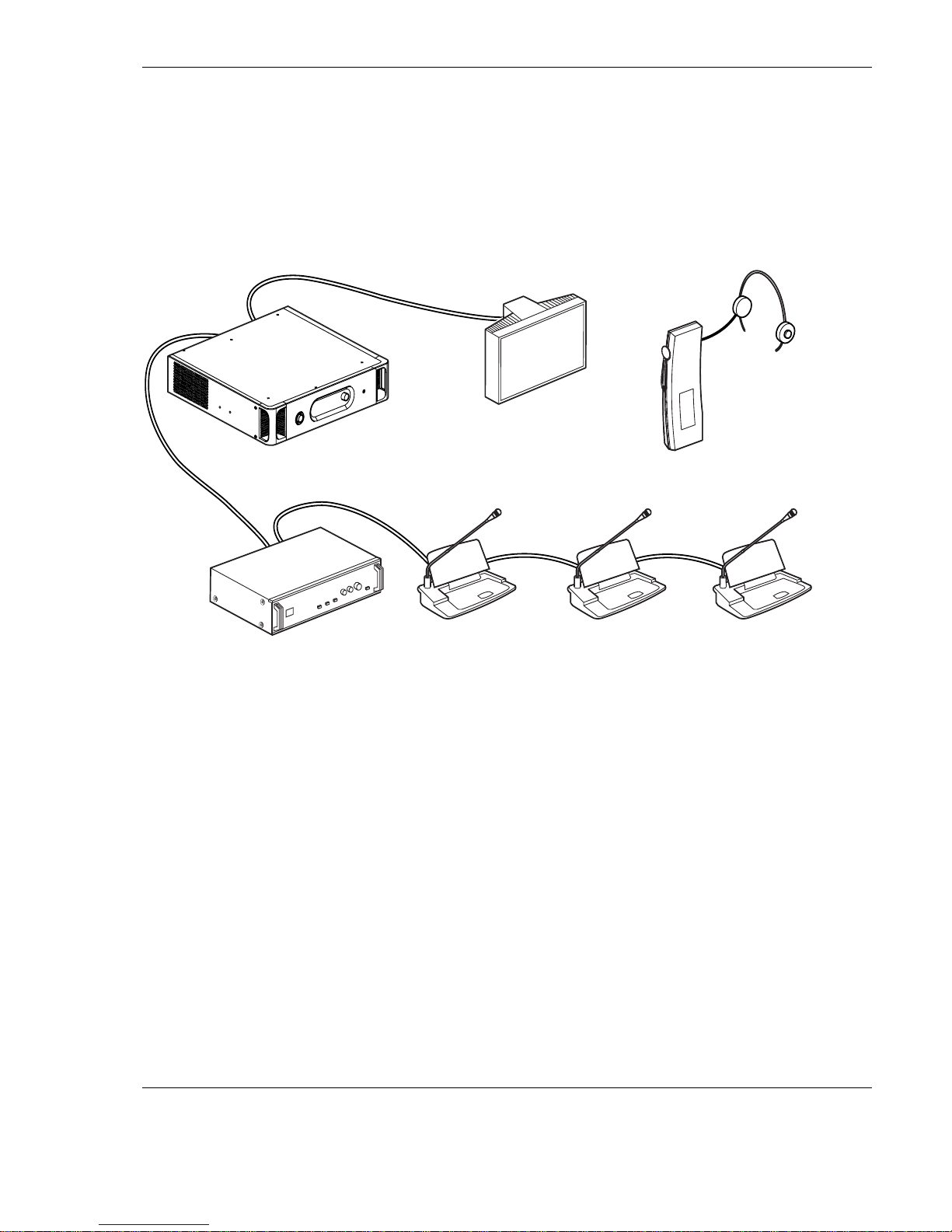
Figure 1.1 Integrus system overview (with DCN-system as input)
The Integrus Digital Infra-red Language Distribution System comprises one or more of the following:
Infra-red transmitter
The transmitter is the core of the Integrus system. Four types are available:
N LBB 4502/04 with inputs for 4 audio channels
N LBB 4502/08 with inputs for 8 audio channels
N LBB 4502/16 with inputs for 16 audio channels
N LBB 4502/32 with inputs for 32 audio channels
Interface modules
One of two different interface modules can be mounted in the transmitter housing to connect the transmitter to a wide range of
conference systems:
N LBB 3423 DCN Interface module to connect to the Digital Congress Network (DCN).
N LBB 3422/1x Symmetrical Audio Input and Interpreters Module to connect to analogue discussion and conference
systems (such as CCS 800) or to LBB 3222/04 6-channel interpreters desks.
Infra-red radiators
Two types of radiators are available:
N LBB 4511/00 medium-power radiator for small/medium conference venues
N LBB 4512/00 high-power radiator for medium/large conference venues
Both types can be switched between full and half power use. They can be mounted on walls, ceilings or floor stands.

6 | en INTEGRUS | Digital Infra-red Language Distribution System
BOSCH Security Systems B.V.| February 2003
Infra-red receivers
Two multi-channel infra-red receivers are available:
N LBB 4540/04 for 4 audio channels
N LBB 4540/32 for 32 audio channels
They can operate with a rechargeable NiMH battery pack or with disposable batteries. Charging circuitry is incorporated in the
receiver.
Charging equipment
Equipment is available for charging and storing 56 infra-red receivers. It is available for portable or fixed-installation
applications.

INTEGRUS | Digital Infra-red Language Distribution System en | 7
BOSCH Security Systems | February 2003
1.2 System technology
1.2.1 IR radiation
The Integrus system is based on transmission by modulated infra-red radiation. Infra-red radiation forms part of the electromagnetic spectrum, which is composed of visible light, radio waves and other types of radiation. It has a wavelength just above
that of visible light. Like visible light, it is reflected from hard surfaces, yet passes through translucent materials such as glass.
The infra-red radiation spectrum in relation to other relevant spectra is shown in Figure 1.2.
100
75
1
4
2
50
25
0
400 500 600 700 800
53
900 1000 nm
%
Figure 1.2 Infra-red radiation spectrum in relation to other spectra
1 Daylight spectrum
2 Sensitivity of the human eye
3 IR radiator
4 Sensitivity of IR sensor
5 Sensitivity of IR sensor with
daylight filter
1.2.2 Signal Processing
The Integrus system uses high frequency carrier signals (typically 2-8 MHz) to prevent interference problems with modern light
sources (see section 1.3.2). The digital audio processing guarantees an constant high audio quality.
The signal processing in the transmitter consists of the following main steps (see Figure 1.3):
1. A/D conversion -Each analogue audio channel is converted to a digital signal.
2. Compression - The digital signals are compressed to increase the amount of information that can be distributed on each
carrier. The compression factor is also related to the required audio quality.
3. Protocol Creation - Groups of up to four digital signals are combined into a digital information stream. Extra fault
algorithm information is added. This information is used by the receivers for fault detection and correction.
4. Modulation - A high frequency carrier signal is phase-modulated with the digital information stream.
5. Radiation – Up to 8 modulated carrier signals are combined and sent to the IR radiators, which convert the carrier signals
to modulated infra-red light.
In the IR receivers a reverse processing is used to convert the modulated infra-red light to separate analogue audio channels.
A/D Conversion
& Compression
A/D Conversion
& Compression
Audio
Channel
Audio
Channel
Protocol Creation
& Modulation
4x
Carrier (to IR Radiators)
4x
Figure 1.3 Overview of the signal processing (for one carrier)

8 | en INTEGRUS | Digital Infra-red Language Distribution System
BOSCH Security Systems B.V.| February 2003
1.2.3 Quality modes
The Integrus system can transmit audio in four different quality modes:
N Mono, standard quality, maximum 32 channels
N Mono, premium quality, maximum 16 channels
N Stereo, standard quality, maximum 16 channels
N Stereo, premium quality, maximum 8 channels
The standard quality mode uses less bandwidth and can be used for transmitting speech. For music the premium quality mode
gives near CD quality.
1.2.4 Carriers and channels
The Integrus system can transmit up to 8 different carrier signals (depending on the transmitter type). Each carrier can contain
up to 4 different audio channels. The maximum number of channels per carrier is dependent on the selected quality modes.
Stereo signals use twice as much bandwidth as a mono signals, premium quality uses twice as much bandwidth as standard
quality.
Per carrier a mix of channels with different quality modes is possible, as long as the total available bandwidth is not exceeded.
The table below lists all possible channel combinations per carrier:
Channel quality
Mono
Standard
Mono
Premium
Stereo
Standard
Stereo
Premium
Bandwidth
4 4 x 10 kHz
2 1 2 x 10 kHz and 1 x 20 kHz
2 1 2 x 10 kHz and 1 x 10 kHz (left) and 1 x 10 kHz (right)
1 1 1 x 20 kHz and 1 x 10 kHz (left) and 1 x 10 kHz (right)
2 2 x 10 kHz (left) and 2 x 10 kHz (right)
2 2 x 20 kHz
Possible
number of
channels
per carrier
1 1 x 20 kHz (left) and 1 x 20 kHz (right)
INTEGRUS | Digital Infra-red Language Distribution System en | 9
BOSCH Security Systems | February 2003
1.3 Aspects of infra-red distribution systems
A good infra-red distribution system ensures that all delegates in a conference venue receive the distributed signals without
disturbance. This is achieved by using enough radiators, placed at well planned positions, so that the conference venue is
covered with uniform IR-radiation of adequate strength.
There are several aspects that influence the uniformity and quality of the infra-red signal, which must be considered when
planning an infra-red radiation distribution system. These are discussed in the next sections.
1.3.1 Directional sensitivity of the receiver
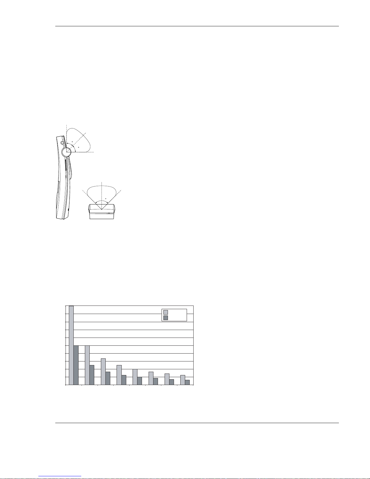
The sensitivity of a receiver is at its best when it is aimed directly towards a radiator. The axis of maximum sensitivity is tilted
upwards at an angle of 45 degrees (see Figure 1.4). Rotating the receiver will decrease the sensitivity. For rotations of less than
+/- 45 degrees this effect is not large, but for larger rotations the sensitivity will decrease rapidly..
45
45
90
Figure 1.4 Directional characteristics of the receivers
1.3.2 The footprint of the radiator
The coverage area of a radiator depends on the number of transmitted carriers and the output power of the radiator. The
coverage area of the LBB 4512 radiator is twice as large as the coverage area of the LBB 4511. The coverage area can also be
doubled by mounting two radiators side by side. The total radiation energy of a radiator is distributed over the transmitted
carriers. When more carriers are used, the coverage area gets proportionally smaller. The receiver requires a strength of the IR
signal of 4 mW/m2 per carrier to work without errors (resulting in a 80 dB S/N ratio for the audio channels). The effect of the
number of carriers on the coverage area can be seen in Figure 1.5 and Figure 1.6. The radiation pattern is the area within which
the radiation intensity is at least the minimum required signal strength.
0
200
400
600
800
1000
1200
1400
1600
1800
2000
12345678
LBB 4511/00
m
2
LBB 4512/00
Figure 1.5 Total coverage area of LBB 4511/00 and LBB 4512/00 for 1 to 8 carriers
10 | en INTEGRUS | Digital Infra-red Language Distribution System
BOSCH Security Systems B.V.| February 2003
&
"
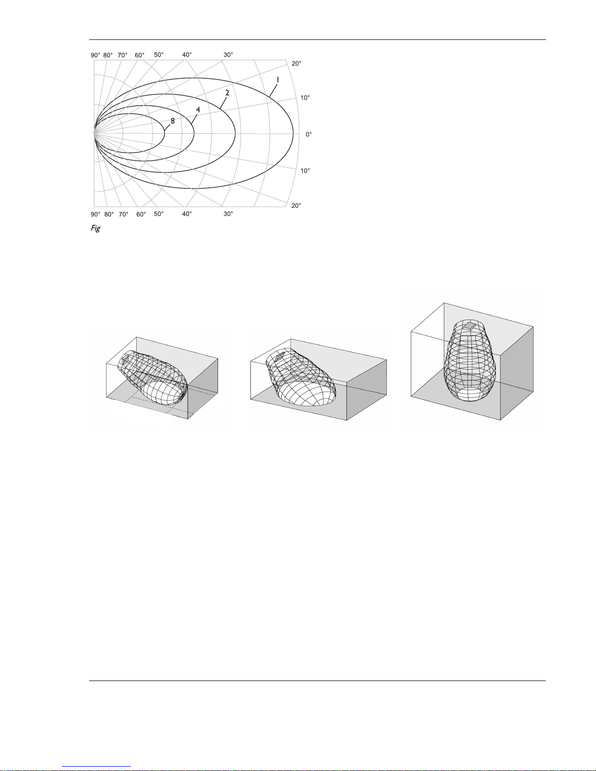
Figure 1.6 Polar diagram of the radiation pattern for 1, 2, 4 and 8 carriers
The cross section of the 3-dimensional radiation pattern with the floor of the conference venue is known as the footprint (the
white area in Figure 1.7 to Figure 1.9). This is the floor area in which the direct signal is strong enough to ensure proper
reception, when the receiver is directed towards the radiator. As shown, the size and position of the footprint depends on the
mounting height and angle of the radiator.
Figure 1.7 The radiator mounted at 15G to
the ceiling
Figure 1.8 The radiator mounted at 45G to
the ceiling
Figure 1.9 The radiator mounted
perpendicular (at 90
G
) to the ceiling
1.3.3 Ambient lighting
The Integrus system is practically immune for the effect of ambient lighting. Fluorescent lamps (with or without electronic
ballast or dimming facility), such as TL lamps or energy saving lamps give no problems with the Integrus system. Also sunlight
and artificial lighting with incandescent or halogen lamps up to 1000 lux give no problems with the Integrus system.
When high levels of artificial lighting with incandescent or halogen lamps, such as spotlights or stage lighting are applied, you
should directly point a radiator at the receivers in order to ensure reliable transmission.
For venues containing large, unscreened windows, you must plan on using additional radiators.
For events taking place in the open air a site test will be required in order to determine the required amount of radiators. With
sufficient radiators installed, the receivers will work without errors, even in bright sunlight.
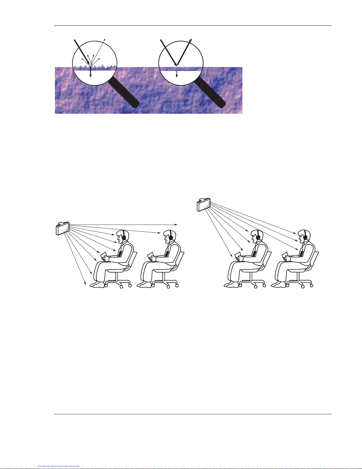
1.3.4 Objects, surfaces and reflections
The presence of objects in a conference venue can influence the distribution of infra-red light. The texture and colour of the
objects, walls and ceilings also plays an important role.
Infra-red radiation is reflected from almost all surfaces. As is the case with visible light, smooth, bright or shiny surfaces reflect
well. Dark or rough surfaces absorb large proportions of the infra-red signal (see Figure 1.10). With few exceptions it cannot
pass through materials that are opaque to visible light.
INTEGRUS | Digital Infra-red Language Distribution System en | 11
BOSCH Security Systems | February 2003
100% 40% 100% 80%
Figure 1.10 The texture of the material determines how much light is reflected and how much is absorbed
Problems caused by shadows from walls or furniture can be solved by ensuring that there are sufficient radiators and that they
are well positioned, so that a strong enough infra-red field is produced over the whole conference area. Care should be taken
not to direct radiators towards uncovered windows, as most of this radiation will subsequently be lost.
1.3.5 Positioning the radiators
Since infra-red radiation can reach a receiver directly and/or via diffused reflections, it is important to take this into account
when considering the positioning of the radiators. Though it is best if receivers pick up direct path infra-red radiation,
reflections improve the signal reception and should therefore not be minimised. Radiators should be positioned high enough
not to be blocked by people in the hall (see Figure 1.11 and Figure 1.12).
Figure 1.11 Infra-red signal blocked by a person in front of the
participant
Figure 1.12 Infra-red signal not blocked by a person in front of
the participant
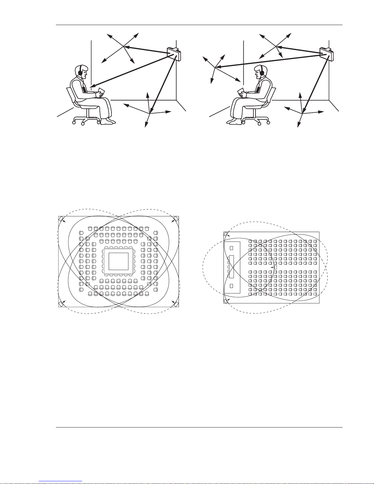
The figures below illustrate how infra-red radiation can be directed to conference participants. In Figure 1.14, the participant is
situated clear from obstacles and walls, so a combination of direct and diffused radiation can be received. Figure 1.13shows the
signal being reflected from a number of surfaces to the participant.
12 | en INTEGRUS | Digital Infra-red Language Distribution System
BOSCH Security Systems B.V.| February 2003
Figure 1.13 Combination of direct and reflected radiation
Figure 1.14 Combination of several reflected signals
For concentrically arranged conference rooms, centrally placed, angled radiators located high up can cover the area very
efficiently. In rooms with few or no reflecting surfaces, such as a darkened film-projection room, the audience should be
covered by direct path infra-red radiation from radiators positioned in front. When the direction of the receiver changes, e.g.
with varying seat arrangements, mount the radiators in the corners of the room (see Figure 1.15).
If the audience is always directed towards the radiators, you do not need radiators at the back (see Figure 1.16).
If the path of the infra-red signals is partially blocked, e.g. under balconies, you should cover the ‘shaded’ area with an
additional radiator (see Figure 1.17).
The figures below illustrate the positioning of the radiators:
Figure 1.15 Radiator position for covering seats in a square
arrangement
Figure 1.16 Radiator positioning in a conference hall with
auditorium seating and podium
INTEGRUS | Digital Infra-red Language Distribution System en | 13
BOSCH Security Systems | February 2003
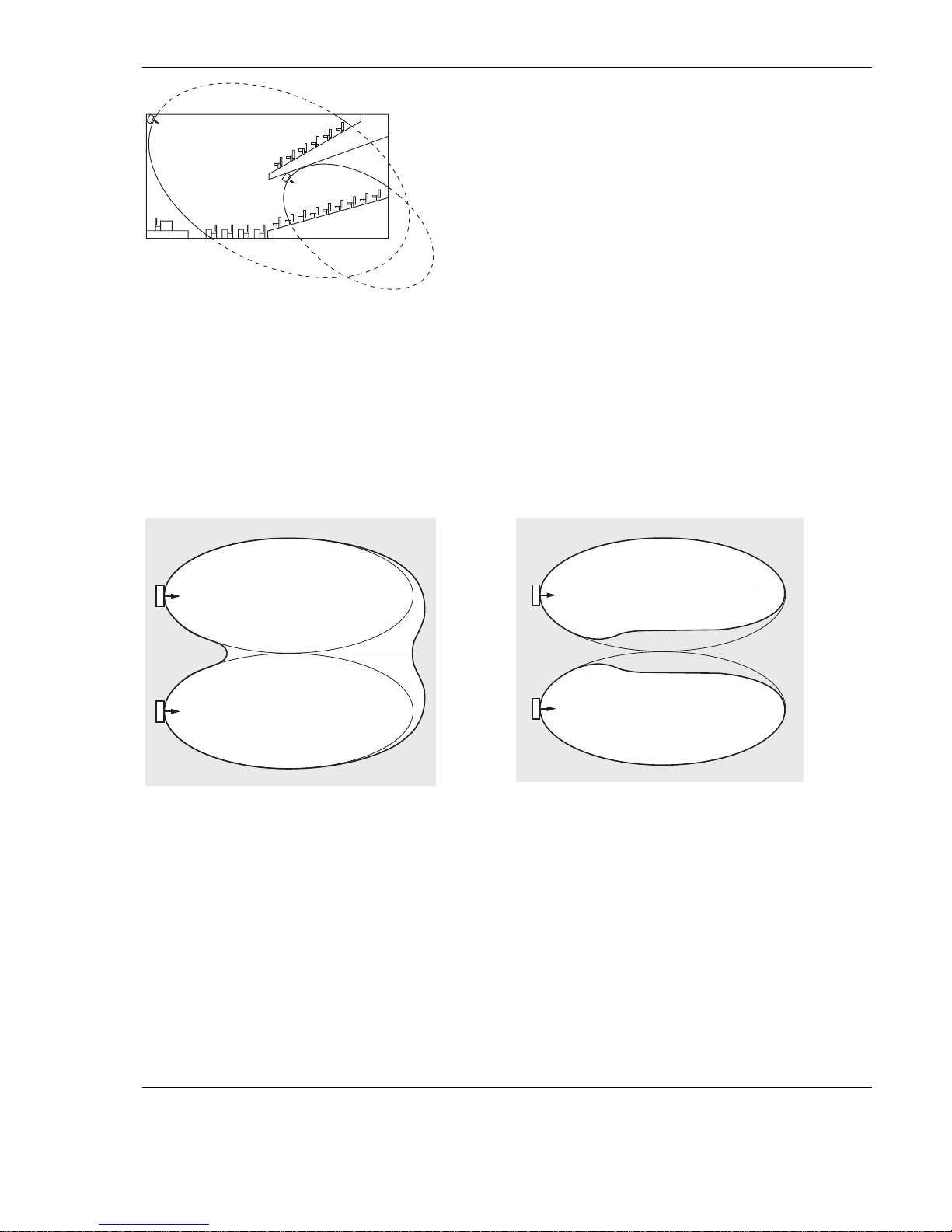
Figure 1.17 Radiator for covering seats beneath a balcony
1.3.6 Overlapping footprints and multipath effects
When the footprints of two radiators partly overlap, the total coverage area can be larger than the sum of the two separate
footprints. In the overlap area the signal radiation power of two radiators are added, which increases the area where the
radiation intensity is larger than the required intensity.
However, differences in the delays of the signals picked up by the receiver from two or more radiators can result in that the
signals cancel each other out (multi path effect). In worst-case situations this can lead to a loss of reception at such positions
(black spots).
Figure 1.18 and Figure 1.19 illustrate the effect of overlapping footprints and differences in signal delays.
Figure 1.18 Increased coverage area caused by added radiation
power
Figure 1.19 Reduced coverage area caused by differences in cable
signal delay
The lower the carrier frequency, the less susceptible the receiver is for differences in signal delays. The signal delays can be
compensated by using the delay compensation switches on the radiators (see section 1.5).
1.4 Planning an Integrus infra-red radiation system
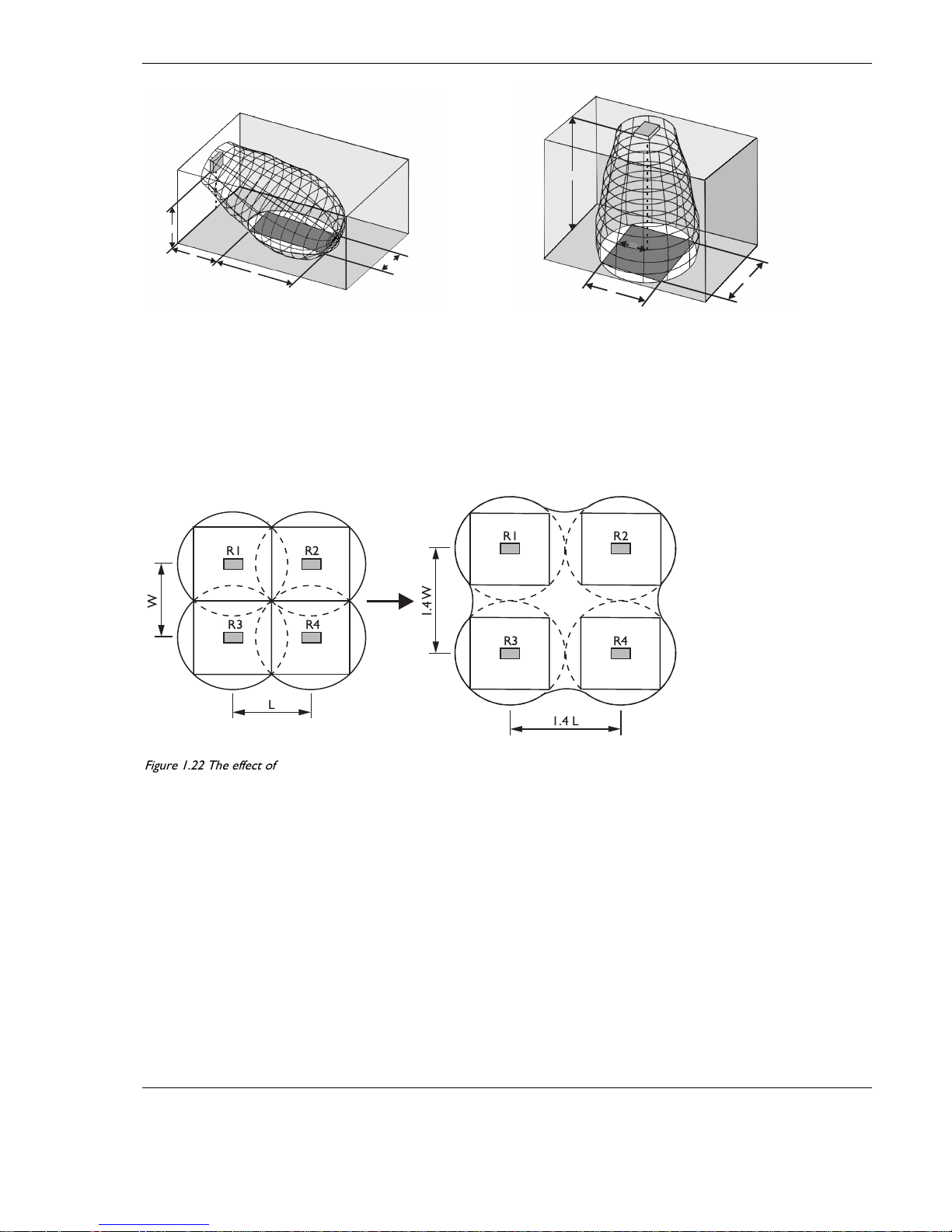
1.4.1 Rectangular footprints
Determining the optimal number of infra-red radiators required to give 100% coverage of a hall can normally only be done by
performing a site test. However, a good estimation can be made by using ‘guaranteed rectangular footprints’. Figure 1.20 and
Figure 1.21 show what is meant by a rectangular footprint. As can be seen, the rectangular footprint is smaller than the total
footprint. Note that in Figure 1.21 the ‘offset’ X is negative because the radiator is actually mounted beyond the horizontal
point at which the rectangular footprint starts.
14 | en INTEGRUS | Digital Infra-red Language Distribution System
BOSCH Security Systems B.V.| February 2003
W
H
L
X
Figure 1.20 A typical rectangular footprint for a mounting angle of
15G
X
W
H
L
Figure 1.21 A typical rectangular footprint for a mounting angle of
90G
The guaranteed rectangular footprints for various number of carriers, mounting heights and mounting angles can be found in
section 7.6. The height is the distance from the reception plane and not from the floor. Guaranteed rectangular footprints can
also be calculated with the footprint calculation tool (available on the documentation CD-ROM). The given values are for one
radiator only, and therefore do not take into consideration the beneficial effects of overlapping footprints. The beneficial effects
of reflections are also not included.
As rule of thumb can be given for systems with up to 4 carriers, that if the receiver can pick up the signal of two adjacent
radiators the distance between these radiators can be increased by a factor 1.4 approximately (see Figure 1.22).
L
R1 R2
R3 R4
R1 R2
R3 R4
W
1.4W
1.4 L
Figure 1.22 The effect of overlapping footprints
1.4.2 Planning radiators
Use the following procedure to plan the radiators:
1. Follow the recommendations in section 1.3 in order to determine the positioning of the radiators
2. Look up (in the table) or calculate (with the footprint calculation tool) the applicable rectangular footprints
3. Draw the rectangular footprints in the lay-out of the room.
4. If the receiver can pick up the signal of two adjacent radiators in some areas, determine the overlap effect and draw the
footprint enlargement(s) in the lay-out of the room.
5. Check whether you have sufficient coverage with the radiators at the intended positions.
6. If not so, add additional radiators to the room.
7. For larger systems and systems with more than 4 carriers, use the Ease-IR simulation program for optimising further the
overlap effect and at the same time taking into account the multi path effect.
See Figure 1.15, Figure 1.16 and Figure 1.17 for examples of a radiator lay out.
INTEGRUS | Digital Infra-red Language Distribution System en | 15
BOSCH Security Systems | February 2003
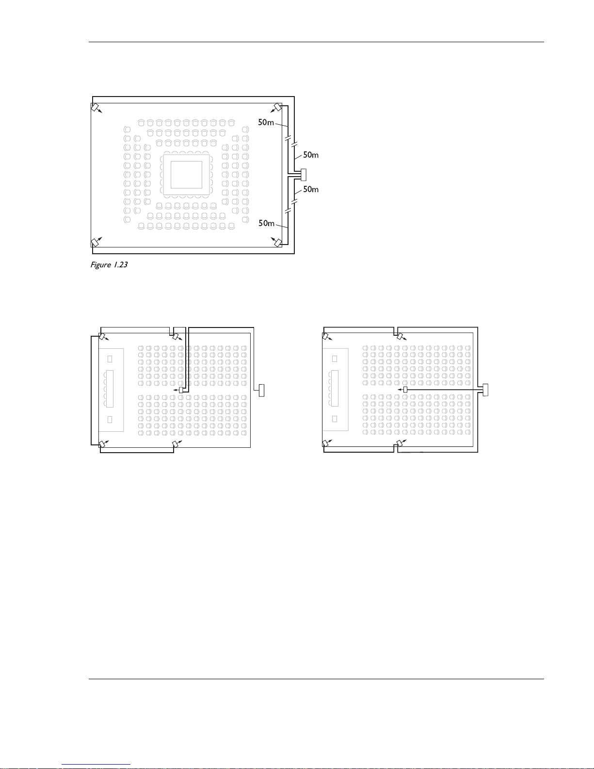
1.4.3 Cabling
Signal delay differences can occur due to differences in the cable length from the transmitter to each radiator. In order to
minimize the risk of black spots, use equal cable length from transmitter to radiator if possible (see Figure 1.23).
50m
50m
50m
50m
Figure 1.23 Radiators with equal cable length
When radiators are loop-through connected, the cabling between each radiator and the transmitter should be as symmetrical as
possible (see Figure 1.24 and Figure 1.25). The differences in cable signal delays can be compensated with the signal delay
compensation switches on the radiators.
Figure 1.24 Asymmetrical arrangement of radiator cabling
(to be avoided)
Figure 1.25 Symmetrical arrangement of radiator cabling
(recommended)

16 | en INTEGRUS | Digital Infra-red Language Distribution System
BOSCH Security Systems B.V.| February 2003
1.5 Setting the radiator delay switches
As described in section 1.3.6, differences in the delays of the signals picked up by the receiver from two or more radiators can
cause black spots as a result of the multi path effect.
The signals picked up by the receiver are delayed by:
N the transmission from transmitter to radiator through the cable (cable signal delay)
N the transmission from radiator to receiver through the air (radiation signal delay)
N for systems with two or more transmitters: the transmission through the slave transmitter(s)
To compensate the signal delay differences, the delay of each radiator can be increased. These signal delays can be set with the
delay switches at the back of the radiator.
The cable signal delays can be determined in the following two ways:
N by measuring the cable lengths
N by measuring the impulse response time with a delay measurement tool
In both cases the cable signal delays can be calculated manually and with the delay switch calculation tool (available on the
documentation CD-ROM).
For systems with one transmitter and radiators directly connected to the transmitter with equal cable lengths, it is not necessary
to calculate the cable signal delays. In that case set the delay switches on all radiators to zero and determine whether to
compensate for radiation signal delay (see section 1.5.3)
The next sections describe how to calculate the delay switch positions manually for systems with one transmitter, or two or
more transmitters.
See the delay switch calculation tool for the procedures how to calculate the delay switch positions automatically.
: The delay switch calculation tool eases the calculation of the delay switch positions.
1.5.1 System with one transmitter
1.5.1.1 Determining delay switch positions by measuring the cable lengths
Use the following procedure to determine the delay switch position based on cable lengths:
1. Look up the cable signal delay per meter of the used cable. The manufacturer specifies this factor.
2. Measure the lengths of the cables between the transmitter and each radiator.
3. Multiply the lengths of the cables between the transmitter and each radiator with the cable signal delay per meter. These are
the cable signal delays for each radiator.
4. Determine the maximum signal delay.
5. Calculate for each radiator the signal delay difference with the maximum signal delay.
6. Divide the signal delay difference by 33. The rounded off figure is the signal delay switch position for that radiator.
7. Add delay switch positions for radiators under a balcony, if applicable (see section 1.5.3)
8. Set the delay switches to the calculated switch positions.
: Turn the delay switches carefully to a new position until you feel that it clicks into position, to prevent that a switch is positioned
between two numbers, which would result in a wrong delay setting.
For systems with a cable length difference of more than 50 meters, it is recommended to use a measurement tool to determine the delay
differences in order to calculate the delay switch positions..
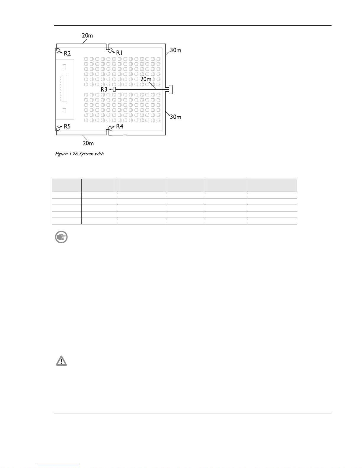
Figure 1.26 and Table 1.1 illustrate the calculation of the cable signal delay.
INTEGRUS | Digital Infra-red Language Distribution System en | 17
BOSCH Security Systems | February 2003
20m
20m
30m
30m
R2
R5 R4
R3
R1
20m
Figure 1.26 System with five radiators and measured cable lengths
Table 1.1 Calculation of the cable signal delays
Radiator
number
Total cable
length [m]
Cable signal delay
per meter [ns/m]
Cable sgnal
delay [ns]
Signal delay
difference [ns]
Delay switch
position
1 30 5.6 30*5.6 = 168 280-168 = 112 112/33 = 3.39 = 3
2 30+20 = 50 5.6 50*5.6 = 280 280-280 = 0 0/33 = 0
3 20 5.6 20*5.6 = 112 280-112 = 168 168/33 = 5.09 = 5
4 30 5.6 30*5.6 = 168 280-168 = 112 112/33 = 3.39 = 3
5 30+20 = 50 5.6 50*5.6 = 280 280-280 = 0 0/33 = 0
The used cable signal delay per meter is an example. Use the actual signal delay per meter in this calculation as specified by the
manufacturer.
1.5.1.2 Determining delay switch positions by using a delay measuring tool
The most accurate way to determine the cable signal delays is to measure the actual signal delay for each radiator as described in
the following procedure:
1. Disconnect the cable from a radiator output of the transmitter and connect this to a delay measurement tool.
2. Disconnect a radiator from this cable.
3. Measure the impulse response time (in ns) of the cable(s) between the transmitter and the radiator.
4. Reconnect the cable to the radiator and repeat steps 2 to 4 for the other radiators that are connected to the same
transmitter output.
5. Reconnect the cable to the transmitter and repeat step 1 to 5 for the other radiator outputs of the transmitter.
6. Divide the impulse response times for each radiator by two. These are the cable signal delays for each radiator.
7. Determine the maximum signal delay.
8. Calculate for each radiator the signal delay difference with the maximum signal delay.
9. Divide the signal delay difference by 33. The rounded off figure is the delay switch position for that radiator.
10. Add delay switch positions to radiators under a balcony, if applicable (see section 1.5.3)
11. Set the delay switches to the calculated delay switch positions.
: Turn the delay switches carefully to a new position until you feel that it clicks into position, to prevent that a switch is positioned
between two numbers, which would result in a wrong delay setting.
18 | en INTEGRUS | Digital Infra-red Language Distribution System
BOSCH Security Systems B.V.| February 2003
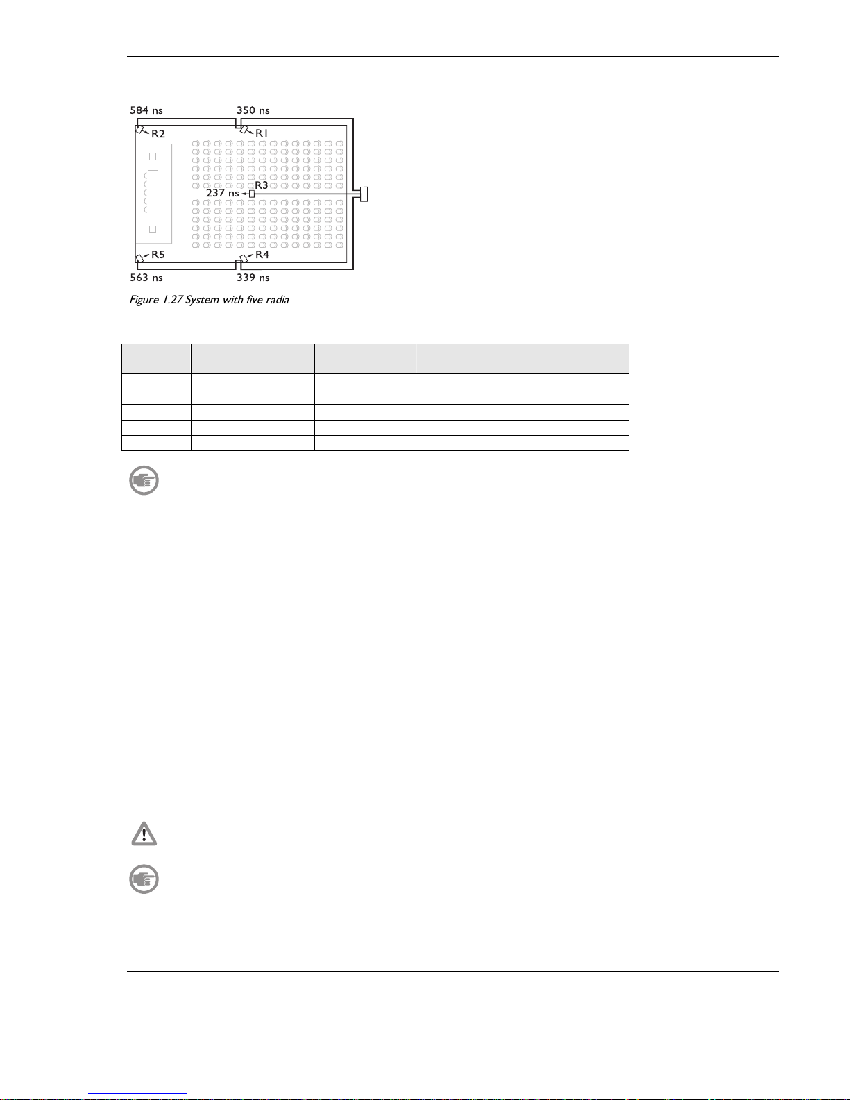
Figure 1.27 and Table 1.2 illustrate the calculation of the signal delays and the delay switch positions.
584 ns 350 ns
563 ns 339 ns
R2
R5 R4
237 ns
R1
R3
Figure 1.27 System with five radiators and measured impulse response times
Table 1.2 Calculation of the delay switch positions of a system with one transmitter
Radiator
number
Impulse response
time [ns]
Cable signal
delay [ns]
Signal delay
difference [ns]
Delay switch
position
1 350 350/2 = 175 292-175 = 117 117/33 = 3.54 = 4
2 584 584/2 = 292 292-292 = 0 0/33 = 0
3 237 237/2 = 118 292-118 = 174 174/33 = 5.27 = 5
4 339 339/2 = 169 292-169 = 123 123/33 = 3.73 = 4
5 563 573/2 = 281 292-281 = 11 11/33 = 0.33 = 0
The calculated delay switch positions based on impulse response time can differ from the calculated delay switch positions based on
cable lengths. This is caused by the accuracy of the measurements and the accuracy of the cable signal delay factor per meter as specified by the
manufacturer of the cable. If the impulse response time is measured correctly, the calculated delay switch positions will be the most accurate
1.5.2 System with two or more transmitters in one room
When radiators in one multi purpose room are connected to two transmitters, an extra signal delay is added by:
N Transmission from master transmitter to slave transmitter (cable signal delay).
N Transmission through the slave transmitter.
Use the following procedure to determine the delay switch positions in a master-slave configuration:
1. Calculate the cable signal delay for each radiator, using the procedures for a system with one transmitter.
2. Calculate the signal delay of the cable between the master and the slave transmitter in the same way as for cables between a
transmitter and a radiator.
3. Add to the cable signal delay of the cable between the master and the slave, the delay of the slave transmitter itself: 33 ns.
This gives the master-to-slave signal delay.
4. Add the master-to-slave signal delay to each radiator connected to the slave transmitter.
5. Determine the maximum signal delay.
6. Calculate for each radiator the signal delay difference with the maximum signal delay.
7. Divide the signal delay difference by 33. The rounded off figure is the signal delay switch position for that radiator.
8. Add delay switch positions to radiators under a balcony, if applicable (see section 1.5.3)
9. Set the delay switches to the calculated delay switch positions.
: Turn the delay switches carefully to a new position until you feel that it clicks into position, to prevent that a switch is positioned
between two numbers, which would result in a wrong delay setting.
: When a master-slave configuration is used for rooms which are always separated, the delay switch positions can be determined per
system and the delay caused by transmission from master to slave transmitter can be ignored.
Figure 1.28, Table 1.1, Table 1.3 and Table 1.4 illustrate the calculation of the extra master-slave signal delay.
 Loading...