


IntuiKey Series
Instruction Manual
EN Digital Keyboard

IntuiKey Series | Instruction Manual | Important Safeguards |
EN | 2 |
|
|
Important Safeguards
1.Read, Follow, and Retain Instructions - All safety and operating instructions should be read and followed before operating the unit. Retain instructions for future reference.
2.Heed Warnings - Adhere to all warnings on the unit and in the operating instructions.
3.Attachments - Attachments not recommended by the product manufacturer should not be used, as they may cause hazards.
4.Installation Cautions - Do not place this unit on an unstable stand, tripod, bracket, or mount. The unit may fall, causing serious injury to a person and serious damage to the unit. Use only manufacturerrecommended accessories, or those sold with the product. Mount the unit per the manufacturer's instructions. Appliance and cart combination should be moved with care. Quick stops, excessive force, or uneven surfaces may cause the appliance and cart combination to overturn.
5.Cleaning - Unplug the unit from the outlet before cleaning. Follow any instructions provided with the unit. Generally, using a damp cloth for cleaning is sufficient. Do not use liquid cleaners or aerosol cleaners.
6.Servicing - Do not attempt to service this unit yourself. Opening or removing covers may expose you to dangerous voltage or other hazards. Refer all servicing to qualified service personnel.
7.Damage Requiring Service - Unplug the unit from the main AC power source and refer servicing to qualified service personnel under the following conditions:
•When the power supply cord or plug is damaged.
•If liquid has been spilled or an object has fallen into the unit.
•If the unit has been exposed to water and/or inclement weather (rain, snow, etc.).
•If the unit does not operate normally, when following the operating instructions. Adjust only those controls specified in the operating instructions. Improper adjustment of other controls may result in damage, and require extensive work by a qualified technician to restore the unit to normal operation.
•If the unit has been dropped or the cabinet damaged.
•If the unit exhibits a distinct change in performance, this indicates that service is needed.
8.Replacement Parts - When replacement parts are required, the service technician should use replacement parts specified by the manufacturer or that have the same characteristics as the original part. Unauthorized substitutions may result in fire, electrical shock or other hazards.
9.Safety Check - Upon completion of servicing or repairs to the unit, ask the service technician to perform safety checks to ensure proper operating condition.
10.Power Sources - Operate the unit only from the type of power source indicated on the label. If unsure of the type of power supply to use, contact your dealer or local power company.
•For units intended to operate from battery power, refer to the operating instructions.
•For units intended to operate with External Power Supplies, use only the recommended approved power supplies.
•For units intended to operate with a limited power source, this power source must comply with EN60950. Substitutions may damage the unit or cause fire or shock.
•For units intended to operate at 24VAC, normal input voltage is 24VAC. Voltage applied to the unit's power input should not exceed 30VAC.
User-supplied wiring, from the 24VAC supply to unit, must be in compliance with electrical codes (Class 2 power levels). Do not ground the 24VAC supply at the terminals or at the unit's power supply terminals.
11.Coax Grounding - If an outside cable system is connected to the unit, ensure that the cable system is grounded. U.S.A. models only - Section 810 of the National Electrical Code, ANSI/NFPA No.70, provides information regarding proper grounding of the mount and supporting structure, grounding of the coax to a discharge unit, size of grounding conductors, location of discharge unit, connection to grounding electrodes, and requirements for the grounding electrode.
12.Grounding - This unit may be equipped with a 3- wire grounding plug (a plug with a third pin, for grounding). This safety feature allows the plug to fit into a grounding power outlet only. If unable to insert the plug into the outlet, contact an electrician to arrange replacement of the obsolete outlet. Do not defeat the safety purpose of the grounding plug.
•Outdoor equipment should only be connected to the unit's inputs after this unit has had its grounding plug connected to a grounded outlet or its ground terminal properly connected to a ground source.
•The unit's input connectors must be disconnected from outdoor equipment before disconnecting the grounding plug or grounding terminal.
•Proper safety precautions such as grounding should be followed for any outdoor device connected to this unit.
13.Lightning - For added protection during a lightning storm, or when this unit is left unattended and unused for long periods of time, unplug the unit from the wall outlet and disconnect the cable system. This will prevent damage to the unit due to lightning and power line surges.
Bosch Security Systems | June 11, 2005

IntuiKey Series | Instruction Manual | Safety Precautions |
EN | 3 |
|
|
For Indoor Product
1.Water and Moisture - Do not use this unit near water - for example, in a wet basement, in an unprotected outdoor installation or in any area classified as a wet location.
2.Object and Liquid Entry - Never push objects of any kind into this unit through openings, as they might touch dangerous voltage points or create short circuits, resulting in a fire or electrical shock. Never spill liquid of any kind on the unit.
3.Power Cord and Power Cord Protection - For units intended to operate with 230VAC, 50Hz, the input and output power cord must comply with the latest versions of IEC Publication 227 or IEC Publication 245.
Power supply cords should be routed so they are not likely to be walked on or pinched. Pay particular attention to location of cords and plugs, convenience receptacles, and the point of exit from the appliance.
4.Overloading - Do not overload outlets and extension cords; this can result in a risk of fire or electrical shock.
For Outdoor Product
Power Lines - An outdoor system should not be located in the vicinity of overhead power lines, electric lights or power circuits, or where it may contact such power lines or circuits. When installing an outdoor system, extreme care should be taken to keep from touching power lines or circuits, as this contact might be fatal. U.S.A. models only - refer to the National Electrical Code Article 820 regarding installation of CATV systems.
For Rack-mount Product
1.Ventilation - Do not place this equipment in a built-in installation or rack, unless proper ventilation is provided, or the manufacturer's instructions were followed. The equipment must not exceed its maximum operating temperature requirements.
2.Mechanical Loading - When rack-mounting the equipment, ensure that a hazardous condition is not created by uneven mechanical loading.
Safety Precautions
CAUTION: TO REDUCE THE RISK OF ELECTRIC SHOCK, DO NOT REMOVE COVER (OR BACK). NO USER SERVICEABLE PARTS INSIDE. REFER SERVICING TO QUALIFIED SERVICE PERSONNEL.
This symbol indicates the presence of uninsulated “dangerous voltage” within the product’s enclosure that can cause an electric shock.
This symbol indicates the presence of important operating and maintenance (servicing) instructions in the literature accompanying the appliance.
Installation should be performed by qualified service personnel only in accordance with the National Electrical Code or applicable local codes.
Power Disconnect. Units with or without ON-OFF switches have power supplied to the unit whenever the power cord is inserted into the power source; however, the unit is operational only when the ON-OFF switch is in the ON position. The power cord is the main power disconnect for all units.
Bosch Security Systems | June 11, 2005

IntuiKey Series | Instruction Manual | FCC Information |
EN | 4 |
|
|
FCC & ICES INFORMATION
(U.S.A. and Canadian Models Only)
This device complies with part 15 of the FCC Rules. Operation is subject to the following two conditions:
(1)This device may not cause harmful interference, and
(2)This device must accept any interference received, including interference that may cause undesired operation.
NOTE: This equipment has been tested and found to comply with the limits for a Class A digital device, pursuant to Part 15 of the FCC Rules and ICES-003 of Industry Canada. These limits are designed to provide reasonable protection against harmful interference when the equipment is operated in a commercial environment. This equipment generates, uses and radiates radio frequency energy, and if not installed and used in accordance with the instruction manual, may cause harmful interference to radio communications. Operation of this equipment in a residential area is likely to cause harmful interference, in which case, the user will be required to correct the interference at his expense.
Intentional or unintentional changes or modifications, not expressly approved by the party responsible for compliance, shall not be made. Any such changes or modifications could void the user’s authority to operate the equipment. If necessary, the user should consult the dealer or an experienced radio/television technician for corrective action. The user may find the following booklet, prepared by the Federal Communications Commission, helpful: How to Identify and Resolve Radio-TV Interference Problems. This booklet is available from the U.S. Government Printing Office, Washington, DC 20402,
Stock No. 004-000-00345-4.
WARNING: This is a Class A product. In a domestic environment, this product may cause radio interference, in which case, the user may be required to take adequate measures.
Sécurité
ATTENTION : POUR ÉVITER TOUT RISQUE D'ÉLECTROCUTION,
N'ESSAYEZ PAS DE RETIRER LE CAPOT (OU LE PANNEAU
ARRIÈRE). CET APPAREIL NE CONTIENT AUCUN COMPOSANT
SUSCEPTIBLE D'ÊTRE RÉPARÉ PAR L'UTILISATEUR. CONFIEZ
LA RÉPARATION DE L'APPAREIL À DU PERSONNEL QUALIFIÉ.
Ce symbole signale que le produit renferme une « tension potentiellement dangereuse » non isolée susceptible de provoquer une électrocution.
Ce symbole invite l'utilisateur à consulter les instructions d'utilisation et d'entretien (dépannage) reprises dans la documentation qui accompagne l'appareil.
Attention : l'installation doit exclusivement être réalisée par du personnel qualifié, conformément au code national d'électricité américain (NEC) ou au code d'électricité local en vigueur.
Coupure de l'alimentation. Qu'ils soient pourvus ou non d'un commutateur ON/OFF, tous les appareils reçoivent de l'énergie une fois le cordon branché sur la source d'alimentation. Toutefois, l'appareil ne fonctionne réellement que lorsque
le commutateur est réglé sur ON. Le débranchement du cordon d'alimentation permet de couper l'alimentation des appareils.
Sicherheitshinweise
VORSICHT: UM EINEN ELEKTRISCHEN SCHLAG ZU
VERMEIDEN, IST DIE ABDECKUNG (ODER RÜCKSEITE) NICHT
ZU ENTFERNEN. ES BEFINDEN SICH KEINE TEILE IN DIESEM
BEREICH, DIE VOM BENUTZER GEWARTET WERDEN
KÖNNEN. LASSEN SIE WARTUNGSARBEITEN NUR VON
QUALIFIZIERTEM WARTUNGSPERSONAL AUSFÜHREN.
Das Symbol macht auf nicht isolierte „gefährliche Spannung" im Gehäuse aufmerksam. Dies kann zu einem elektrischen Schlag führen.
Der Benutzer sollte sich ausführlich über Anweisungen für die Bedienung und Instandhaltung (Wartung) in den begleitenden Unterlagen informieren.
Achtung! Die Installation sollte nur von qualifiziertem
Kundendienstpersonal gemäß jeweils zutreffender
Elektrovorschriften ausgeführt werden.
Unterbrechung des Netzanschlusses. Geräte mit oder ohne Netzschalter haben Spannung am Gerät anliegen, sobald der Netzstecker in die Steckdose gesteckt wird. Das Gerät ist jedoch nur betriebsbereit, wenn der Netzschalter (EIN/AUS) auf EIN steht. Wenn das Netzkabel aus der Steckdose gezogen wird, ist die Spannungszuführung zum Gerät vollkommen unterbrochen.
Precauciones de Seguridad
PRECAUCIÓN: PARA DISMINUIR EL RIESGO DE DESCARGA ELÉCTRICA, NO RETIRE LA CUBIERTA (NI LA PARTE POSTERIOR). NO EXISTEN PIEZAS DE RECAMBIO EN EL INTERIOR DEL EQUIPO. EL PERSONAL DE SERVICIO CUALIFICADO SE ENCARGA DE REALIZAR LAS REPARACIONES.
Este símbolo indica que existen puntos de tensión peligrosos sin aislamiento dentro de la cubierta de la unidad. Estos puntos pueden constituir un riesgo de descarga eléctrica.
El usuario debe consultar las instrucciones de funcionamiento y mantenimiento (reparación) en la documentación que se suministra con el aparato.
Atención: la instalación la debe realizar únicamente personal cualificado de conformidad con el National Electric Code o las normas aplicables en su país.
Desconexión de la alimentación. Las unidades con o sin interruptores de encendido/apagado reciben alimentación eléctrica siempre que el cable de alimentación esté conectado a la fuente de alimentación. Sin embargo, la unidad sólo funciona cuando el interruptor está en la posición de encendido. El cable de alimentación es la principal fuente de desconexión de todas las unidades.
Bosch Security Systems | June 11, 2005

IntuiKey Series | Instruction Manual | Safety Precautions |
EN | 5 |
|
|
Veiligheidsmaatregelen |
|
Medidas de Segurança |
||||||||||||||||||||||||||||
|
|
|
|
|
|
|
|
|
|
|
|
|
|
|
|
|
|
|
|
|
|
|
|
|
|
|
|
|
|
|
|
|
|
|
|
|
|
|
|
|
|
|
|
|
|
|
|
|
|
|
|
|
|
|
|
|
|
|
|
|
|
|
|
|
|
|
|
|
|
|
|
|
|
|
|
|
|
|
|
|
|
|
|
|
|
|
|
|
|
|
|
|
|
|
|
|
|
|
|
|
|
|
|
|
|
|
|
|
|
|
|
|
|
|
|
|
|
|
|
|
|
|
|
|
|
|
|
|
|
|
|
|
|
|
|
|
|
|
|
|
|
|
|
|
|
|
|
|
|
|
|
|
|
|
|
|
|
|
|
|
|
|
|
|
|
|
|
|
|
|
|
|
|
|
|
|
|
|
|
|
|
|
|
|
|
|
|
|
|
|
|
|
|
|
|
|
|
|
|
|
|
|
|
|
|
|
|
|
|
|
|
|
|
|
|
|
|
|
|
|
|
|
|
|
|
|
|
|
|
|
|
|
|
|
|
|
|
|
|
|
|
|
|
|
|
|
|
VOORZICHTIG: OPEN DE BEHUIZING OF DE ACHTERKANT VAN HET APPARAAT NIET. ZO VERMINDERT U HET RISICO OP ELEKTRISCHE SCHOKKEN. IN HET APPARAAT BEVINDEN ZICH GEEN ONDERDELEN DIE U ZELF KUNT REPAREREN. LAAT SERVICE EN ONDERHOUD UITVOEREN DOOR GEKWALIFICEERD PERSONEEL.
Dit symbool geeft aan dat er binnen in het apparaat ongeïsoleerde, gevaarlijke spanning aanwezig is die mogelijk elektrische schokken kan veroorzaken.
De gebruiker dient de bedieningsen onderhoudsvoorschriften te raadplegen in de documentatie die werd meegeleverd met het apparaat.
Attentie: het apparaat mag alleen door gekwalificeerd personeel worden geïnstalleerd. De installatie dient in overeenstemming met de nationale elektrische richtlijnen of de van toepassing zijnde lokale richtlijnen te worden uitgevoerd.
Spanning uitschakelen. Apparatuur met of zonder aan-uitschakelaar staat onder spanning zolang de stekker is aangesloten op de wandcontactdoos. De apparatuur is uitsluitend in werking als de aan-uitschakelaar aan staat. Het netsnoer is de "hoofdschakelaar" voor alle apparatuur.
CUIDADO: PARA REDUZIR O RISCO DE CHOQUE
ELÉCTRICO, NÃO RETIRE A TAMPA (OU A PARTE
POSTERIOR). NO INTERIOR, NÃO EXISTEM PEÇAS QUE
POSSAM SER REPARADAS PELO UTILIZADOR. REMETA A
ASSISTÊNCIA PARA OS TÉCNICOS QUALIFICADOS.
Este símbolo indica a presença de "tensão perigosa" não isolada dentro da estrutura do produto, o que pode constituir risco de choque eléctrico.
O utilizador deve consultar as instruções de funcionamento e manutenção (assistência) nos documentos que acompanham o aparelho.
Atenção: a instalação deve ser executada apenas por técnicos qualificados da assistência, de acordo com o código eléctrico nacional ou os códigos locais aplicáveis.
Corte de corrente. As unidades com ou sem interruptores ON-OFF (ligar/desligar) recebem corrente sempre que o fio de alimentação está introduzido na fonte de alimentação; contudo, a unidade apenas está operacional quando o interruptor ON-OFF está na posição ON. O fio de alimentação destina-se a desligar a corrente em todas as unidades.
Sicurezza
ATTENZIONE: PER RIDURRE IL RISCHIO DI SCOSSE ELETTRICHE NON RIMUOVERE LA COPERTURA (O IL PANNELLO POSTERIORE). L'UNITÀ NON CONTIENE COMPONENTI INTERNI RIPARABILI DALL'UTENTE. PER QUALSIASI INTERVENTO, RIVOLGERSI A PERSONALE TECNICO QUALIFICATO.
Questo simbolo indica la presenza di "tensione pericolosa" non isolata all'interno del contenitore del prodotto. Ciò comporta un potenziale rischio di scosse elettriche.
Si consiglia di consultare le istruzioni operative e di manutenzione (interventi tecnici) contenute nella documentazione fornita con il dispositivo.
Attenzione: l'installazione deve essere effettuata esclusivamente da personale tecnico qualificato in conformità con il National Electrical Code o con le normative locali vigenti.
Scollegamento dell'alimentazione. Le unità dotate o sprovviste di interruttori ON-OFF vengono alimentate quando si inserisce il cavo nella presa dell'alimentazione. L'unità è tuttavia in funzione solo quando l'interruttore ON-OFF si trova nella posizione ON. Il cavo di alimentazione costituisce il dispositivo di scollegamento dell'alimentazione principale per tutte le unità.
Bosch Security Systems | June 11, 2005

IntuiKey Series | Instruction Manual | Contents |
EN | 6 |
|
|
Table of Contents |
|
|
Important Safeguards . . . . . . . . . . . . . . . . . . . . . . . . . . . . . . . . . . . . . . . . . . . . . . . . . . . . . . . . . . . . . . . . . . . |
. .2 |
|
FCC Information . . . . . . . . . . . . . . . . . . . . . . . . . . . . . . . . . . . . . . . . . . . . . . . . . . . . . . . . . . . . . . . . . . . . . . . |
.4 |
|
1 |
INTRODUCTION . . . . . . . . . . . . . . . . . . . . . . . . . . . . . . . . . . . . . . . . . . . . . . . . . . . . . . . . . . . . . . . . |
.7 |
1.1 |
Guide to this Manual . . . . . . . . . . . . . . . . . . . . . . . . . . . . . . . . . . . . . . . . . . . . . . . . . . . . . . . . . . . . . . . |
.7 |
1.2 |
Unpacking . . . . . . . . . . . . . . . . . . . . . . . . . . . . . . . . . . . . . . . . . . . . . . . . . . . . . . . . . . . . . . . . . . . . . . . |
.7 |
1.3 |
Service . . . . . . . . . . . . . . . . . . . . . . . . . . . . . . . . . . . . . . . . . . . . . . . . . . . . . . . . . . . . . . . . . . . . . . . . . . |
.7 |
1.4 |
Understanding the IntuiKey . . . . . . . . . . . . . . . . . . . . . . . . . . . . . . . . . . . . . . . . . . . . . . . . . . . . . . . . . . |
.8 |
2 |
INSTALLATION . . . . . . . . . . . . . . . . . . . . . . . . . . . . . . . . . . . . . . . . . . . . . . . . . . . . . . . . . . . . . . . . . . |
.9 |
2.1 |
Determining the IntuiKey System Configuration . . . . . . . . . . . . . . . . . . . . . . . . . . . . . . . . . . . . . . . . . . |
.9 |
2.2 |
Mounting the IntuiKey . . . . . . . . . . . . . . . . . . . . . . . . . . . . . . . . . . . . . . . . . . . . . . . . . . . . . . . . . . . . . . |
10 |
2.3 |
Connecting to the IntuiKey . . . . . . . . . . . . . . . . . . . . . . . . . . . . . . . . . . . . . . . . . . . . . . . . . . . . . . . . . . |
10 |
2.4 |
KBD-Universal (RS-232 Protocol) Installation . . . . . . . . . . . . . . . . . . . . . . . . . . . . . . . . . . . . . . . . . . . . |
11 |
2.5 |
Implementing Terminal Mode with the RS-232 Protocol . . . . . . . . . . . . . . . . . . . . . . . . . . . . . . . . . . . |
16 |
3 |
OPERATION . . . . . . . . . . . . . . . . . . . . . . . . . . . . . . . . . . . . . . . . . . . . . . . . . . . . . . . . . . . . . . . . . . . . |
16 |
3.1 |
Learning the IntuiKey Components . . . . . . . . . . . . . . . . . . . . . . . . . . . . . . . . . . . . . . . . . . . . . . . . . . . . |
16 |
3.2 |
Navigating the System with the IntuiKey Keyboard . . . . . . . . . . . . . . . . . . . . . . . . . . . . . . . . . . . . . . . . |
17 |
3.3 |
Alarm/Alert/Auction Indication . . . . . . . . . . . . . . . . . . . . . . . . . . . . . . . . . . . . . . . . . . . . . . . . . . . . . . . |
18 |
3.4 |
Configuring the IntuiKey Keyboard . . . . . . . . . . . . . . . . . . . . . . . . . . . . . . . . . . . . . . . . . . . . . . . . . . . . |
18 |
4 |
CONTROLLING ALLEGIANT SERIES VIDEO SWITCHES . . . . . . . . . . . . . . . . . . . . . . . . . . . . . |
20 |
4.1 |
The Allegiant Main Control Menu . . . . . . . . . . . . . . . . . . . . . . . . . . . . . . . . . . . . . . . . . . . . . . . . . . . . |
20 |
4.2 |
Programming/Controlling Allegiant Functions . . . . . . . . . . . . . . . . . . . . . . . . . . . . . . . . . . . . . . . . . . . |
21 |
4.3 |
Allegiant Error Messages . . . . . . . . . . . . . . . . . . . . . . . . . . . . . . . . . . . . . . . . . . . . . . . . . . . . . . . . . . . . |
29 |
4.4 |
ADIM Error Messages . . . . . . . . . . . . . . . . . . . . . . . . . . . . . . . . . . . . . . . . . . . . . . . . . . . . . . . . . . . . . . |
31 |
5 |
CONTROLLING DIVAR SERIES DIGITAL VIDEO RECORDERS . . . . . . . . . . . . . . . . . . . . . . . |
32 |
5.1 |
The Divar Main Control Menu . . . . . . . . . . . . . . . . . . . . . . . . . . . . . . . . . . . . . . . . . . . . . . . . . . . . . . . |
32 |
5.2 |
Programming/Controlling DVR Functions . . . . . . . . . . . . . . . . . . . . . . . . . . . . . . . . . . . . . . . . . . . . . . |
33 |
5.3 |
DVR Error Messages . . . . . . . . . . . . . . . . . . . . . . . . . . . . . . . . . . . . . . . . . . . . . . . . . . . . . . . . . . . . . . . |
36 |
6 |
CONTROLLING SYSTEM 4 VIDEO MULTIPLEXERS . . . . . . . . . . . . . . . . . . . . . . . . . . . . . . . . . |
37 |
6.1 |
The MUX Main Control Menu . . . . . . . . . . . . . . . . . . . . . . . . . . . . . . . . . . . . . . . . . . . . . . . . . . . . . . . |
37 |
6.2 |
Programming/Controlling MUX Functions . . . . . . . . . . . . . . . . . . . . . . . . . . . . . . . . . . . . . . . . . . . . . . |
38 |
6.3 |
MUX Error Messages . . . . . . . . . . . . . . . . . . . . . . . . . . . . . . . . . . . . . . . . . . . . . . . . . . . . . . . . . . . . . . . |
41 |
7 |
TROUBLESHOOTING . . . . . . . . . . . . . . . . . . . . . . . . . . . . . . . . . . . . . . . . . . . . . . . . . . . . . . . . . . . . |
41 |
7.1 |
System . . . . . . . . . . . . . . . . . . . . . . . . . . . . . . . . . . . . . . . . . . . . . . . . . . . . . . . . . . . . . . . . . . . . . . . . . . . |
41 |
7.2 |
Keyboard . . . . . . . . . . . . . . . . . . . . . . . . . . . . . . . . . . . . . . . . . . . . . . . . . . . . . . . . . . . . . . . . . . . . . . . . |
41 |
7.3 |
Camera Control . . . . . . . . . . . . . . . . . . . . . . . . . . . . . . . . . . . . . . . . . . . . . . . . . . . . . . . . . . . . . . . . . . . |
42 |
7.4 |
Miscellaneous . . . . . . . . . . . . . . . . . . . . . . . . . . . . . . . . . . . . . . . . . . . . . . . . . . . . . . . . . . . . . . . . . . . . . |
42 |
APPENDIX A: IntuiKey Menu Reference . . . . . . . . . . . . . . . . . . . . . . . . . . . . . . . . . . . . . . . . . . . . . . . . . . . . |
43 |
|
APPENDIX B: Camera Control Command Reference . . . . . . . . . . . . . . . . . . . . . . . . . . . . . . . . . . . . . . . . . . |
46 |
|
APPENDIX C: Security Information . . . . . . . . . . . . . . . . . . . . . . . . . . . . . . . . . . . . . . . . . . . . . . . . . . . . . . . . |
52 |
|
Bosch Security Systems | June 11, 2005

IntuiKey Series | Instruction Manual | Introduction |
EN | 7 |
|
|
1INTRODUCTION TO THE INTUIKEY DIGITAL KEYBOARD SERIES
1.1Guide to this Manual
This manual contains all the information necessary to safely install and operate the IntuiKey Digital
Keyboard. Consult the Table of Contents for a detailed list of topics covered. Step-by-step procedures, illustrations, and sample menus guide you through each phase of IntuiKey setup and operation.
Throughout the manual, you will see sample drawings of each menu as they appear on the keyboard. These drawings display the softkey text in relation to the Softkey. For the purposes of this manual, each key is numbered from 1 to 14, using the convention found in FIGURE 1-1.
1 |
8 |
2 |
9 |
3 |
10 |
4 |
11 |
5 |
12 |
6 |
13 |
7 |
14 |
FIGURE 1-1 Softkey Numbering Guide
Following the menu diagram, the function of each key is described in a paragraph indicated with an Icon such as " 1 " clearly identifying the particular softkey.
Installation of the IntuiKey includes mounting and connecting the unit to other system components. The plug and play design makes installation and setup of the unit quick and easy.
Operating instructions are provided in several sections of the manual. SECTION 3 covers basic keyboard navigation, while SECTIONS 4 through 6 are devoted specifically to keyboard control of the products. Be aware that some instructions are model-specific; be sure to read the appropriate information for your IntuiKey model.
The Appendices of this manual contain a complete listing of the IntuiKey System Control menus.
1.2Unpacking
Unpack carefully. This electronic equipment should be handled with care to prevent damage to the unit. Check for the following items:
•IntuiKey Keyboard with Integral Joystick
•Instructions for Use (manual)
•10 ft (3 m) power cable(s)
•390 Ω Terminator (p/n 303-2728-001)
If any items appear to have been damaged in shipment, replace the item(s) properly in the shipping carton and notify the shipping company. If any items are missing, notify your Bosch Security Systems Sales Representative or Customer Service Representative.
NOTE: The shipping carton is the safest container in which to transport the unit. Save it and all packing materials for future use.
1.3Service
If the unit needs servicing, contact the nearest Bosch Security Systems Service Center for authorization to return and shipping instructions.
Service Centers
USA
Phone: 800-366-2283 or 717-735-6638 Fax: 800-366-1329 or 717-735-6639
CCTV Spare Parts
Phone: 800-894-5215 or 408-956-3853 or 3854 Fax: 408-957-3198
E-mail: BoschCCTVparts@ca.slr.com Canada
Phone: 514-738-2434
Europe, Middle East & Asia Pacific Region Phone: 32-1-440-0711
For additional information, see www.boschsecurity.com.
Bosch Security Systems | June 11, 2005

IntuiKey Series | Instruction Manual | Introduction |
EN | 8 |
|
|
1.4Understanding the IntuiKey
The IntuiKey provides easy, full-function system control and programming of a variety of BoschCSI security products including Allegiant Switchers, Divar Series digital video recorders, System4® Multiplexers, VCRs and the ADIM integrated Allegiant/Hi-Q™ digital recording system. System cameras can be controlled through any of these devices linked to the keyboard. Backwards compatibility with existing Bosch products enables the IntuiKey’s integration into almost any system configuration (no additional devices/interfaces necessary).
The IntuiKey user interface simplifies system programming by providing intuitive menus, allowing easy and flexible system control navigation. Using the optional KBD-SFTCFG software package (sold separately), customized menu screens can be
programmed to activate Allegiant Command Script macro functions. In addition, this PC-based software supports individualized labeling of the softkey text displays.
The IntuiKey is available in two models, each with an integral, variable speed pan/tilt/zoom joystick. The KBD-Universal provides control of any combination of system components, including Allegiant Switchers, Divar DVRs, and System4 Multiplexers. The KBDUniversal model also supports the ability to operate in a Terminal mode. In Terminal mode, the operation of the keyboard is completely controlled by third-party software via an RS-232 interface. The KBD-Digital provides control of Divar digital video recorders and System4 Multiplexers. Optional equipment available from Bosch for use with the IntuiKey Keyboards includes an external power supply, rack mount kit, and keyboard extenders.
The following chart provides basic operating specifications:
SPECIFICATIONS
Electrical |
|
Mechanical |
|
|
Operating |
|
Construction |
|
|
Voltage: |
12 – 15 VDC (supplied by any one or combination |
Finish: |
Charcoal |
|
|
of Allegiant switcher, Divar digital video recorder, |
Width: |
12.00 in |
327.66 mm |
|
System4 Multiplexer, and/or optional power supply). |
Depth: |
7.518 in |
190.95 mm |
Power: |
5 Watts Nominal. |
Height: |
2.969 in |
75.41 mm |
Signal: |
A: Allegiant; 2 wire RS-485, 9600 Baud, 8 bits, |
Weight: |
2.62 lb |
1.19 kg |
No parity, 1 Stop bit. |
Connectors: |
|
B: Mux/DVR; 2 wire RS-485, 19,200 Baud, 8 bits, No |
A: Allegiant RJ-11 Data/Power. |
|
parity, 1 |
Stop bit. |
B: MUX/DVR RJ/11 Data/Power. |
C: RS-232 |
Serial Port; RS-232 RTS/CTS Handshaking, |
C: Aux Power (Optional) 12 VDC Bayonet Plug. |
9600/19,200 Baud, 8 bits, No parity, 1 Stop bit. |
D: RS-232 Serial Port; Male Null Modem |
|
9-pin Dsub. Data Only.
Compatibility Backwards compatible with all Allegiant systems utilizing variable speed protocol (CPU Firmware 5.3 and higher, released 6/94). Compatible with all Divar Series of digital video recorders. Backwards compatible with all System4 Multiplexers.
Bosch Security Systems | June 11, 2005

IntuiKey Series | Instruction Manual | Installing the IntuiKey Digital Keyboard |
EN | 9 |
|
|
2INSTALLING THE INTUIKEY DIGITAL KEYBOARD
2.1Determining the IntuiKey System Configuration
Before the IntuiKey is mounted or connected to other system components, system configuration must be determined.
The IntuiKey is capable of controlling up to thirty (30) multiplexers/DVRs and one (1) video switcher simultaneously. FIGURE 2-1 illustrates basic IntuiKey system configuration with these devices. If more than one IntuiKey is to be connected to a single multiplexer or group of daisy-chained multiplexers, a keyboard port expander must be added. The Allegiant Series of video switchers have a varying number of keyboard ports
KBD-Digital
RS-485
depending on model number. If more than eight keyboards are required on one of the larger Allegiant Series Switchers, an Allegiant keyboard expander must be added.
NOTE: Bosch offers the following Keyboard Expanders:
•For Use with Allegiant Series Switchers: LTC 8714 – Keyboard Port Expander LTC 8715 – Keyboard Expander
•For Use with Divar Series DVRs, or System4 Video Multiplexers:
LTC 2604 – Keyboard Port Expander
Please contact your Bosch Security Systems Sales Representative for more information.
Divar Digital
Video Recorder
One IntuiKey to One Device
KBD-Universal
|
Divar Digital |
Divar Digital |
Divar Digital |
|
RS-485 |
Video Recorder |
Video Recorder |
Video Recorder |
|
# 1 |
# 2 |
# 30 |
||
|
||||
|
RS-485 |
Allegiant Series |
|
|
|
Video Switcher |
|
||
|
|
|
||
|
One IntuiKey to Multiple Devices |
|
||
KBD-Digital
KBD-Universal
|
LTC 2604 |
System4 |
System4 |
RS-485 |
Keyboard |
Multiplexer |
Multiplexer |
|
Expander |
|
|
LTC 2601/00 |
Multiple Keyboard Models to Multiple System4®Multiplexers |
||
KBD-Universal |
KBD-Digital |
|
|
|
|
|
|
|
|
||
RS-485 |
LTC 2604 |
Divar Digital |
Divar Digital |
||
Keyboard |
Video Recorder |
Video Recorder |
|||
|
|||||
|
Expander |
|
|
||
KBD-Digital |
RS-485 |
Optional |
Optional |
Allegiant Series |
|
|
|||||
|
|
LTC 8714 |
LTC 8715 |
Video Switcher |
|
|
|
Expander |
Expander |
|
|
KBD-Universal |
KBD-Universal |
|
|
Optional ADIM |
|
|
|
|
|||
|
|
|
RS-232 |
Digital Recording |
|
|
|
|
System |
||
|
|
|
|
||
|
Multiple Keyboards to Multiple Devices |
|
|||
FIGURE 2-1 Basic IntuiKey System Configurations
Bosch Security Systems | June 11, 2005
IntuiKey Series | Instruction Manual | Installing the IntuiKey Digital Keyboard |
EN | 10 |
|
|
System power connections must also be considered. Depending on the distance between the keyboard and devices under control, an external power supply may be needed according to the following specifications:
Distance from Keyboard |
Optional Equipment |
to Device under Control* |
Needed |
|
|
Less than 10 ft (3.5 m) |
NONE |
|
|
Between 10 ft (3.5 m) |
KBD-120PS/KBD-220PS |
and 100 ft (30 m) |
External Power Supply |
Greater than 100 ft (30 m) |
LTC 8557/60(50) |
|
Keyboard Extender |
|
|
*NOTE: Distances may vary depending on the number of keyboards connected.
2.2Mounting the IntuiKey
The IntuiKey LCD displays are readable in all but direct sunlight conditions. Locate the keyboard on a flat horizontal surface, with an optimal LCD viewing angle of 0 to 20 degrees from vertical. Display contrast levels are software-controlled and may be adjusted
via the Keyboard Control Menu (as described in SECTION 3.4). An optional rack mount kit may also be used.
2.3Connecting to the IntuiKey
1.Refer to FIGURE 2-2 for details on the input/output connections supplied by the IntuiKey Keyboard. Four connectors are located on the IntuiKey rear panel: (2) RJ-11 connectors,
(1) female 9-pin sub-D connector, and a DC power jack. The RJ-11 connectors are labeled as Allegiant and MUX/DVR, and the 9-pin sub-D is labeled
RS-232 Serial Port.
Allegiant |
|
RS-232 |
MUX/DVR |
DC Power |
Serial Port |
MUX / DVR |
ALLEGIANT |
12 VDC |
RS-232 SERIAL PORT |
Cable Strain Reliefs
FIGURE 2-2 Back Panel Connections of IntuiKey
ATTENTION: To ensure proper system functioning and to prevent damage to the unit, it is critical that only Allegiant devices be connected to the Allegiant connector, and Multiplexer/DVR devices be connected to the MUX/DVR connector.
2.If desired, the data/power cables can be looped through either of the two tabs found at the bottom of the rear panel to increase strain relief capabilities.
3.Review the configuration options shown in FIGURE 2-4. Make the necessary keyboard data and power connections that are best suited to your system requirements based on these diagrams. When connecting to Divar DVRs or System4 Multiplexers, attach the supplied 390 Ohm terminator to the Out connector on the last device.
NOTE: In systems having multiple Divar DVRs or multiple System4 Multiplexers, use the front panel controls on the video devices to assign appropriate address numbers and starting camera numbers. The IntuiKey will not properly recognize the video devices if there are conflicting addresses in the system.
4.After power is applied, the keyboard initializes and displays the following:
KBD – Universal |
|
|
KBD – Universal |
||
|
Bosch Security System |
||||
Bosch Security System |
Firmware Ver: |
x:xx |
|||
Copyright 2003 |
|
|
|
|
|
Protocol: |
|
.6P |
|
|
|
Firmware Ver: |
x:xx |
Prod |
Mon |
||
Bootldr Ver: |
x:xx |
|
|
|
|
Hardware Ver: |
x:xx |
Clr |
|
Shot |
|
|
|
|
|
||
|
|
|
1 |
2 |
3 |
|
|
|
4 |
5 |
6 |
Press [CLR] key to |
|
|
|
||
|
Exit |
|
7 |
8 |
9 |
|
|
|
0 |
|
|
FIGURE 2-3 |
Initial Power-up Display |
|
|
||
5.After a brief pause (or immediately after the CLR button is pressed), the keyboard will perform a brief search for connected devices.
NOTE: On initial power-up, factory reset, or firmware upgrade, the IntuiKey displays a Language Menu. Select the desired language by pressing the softkey next to the language title. If additional languages are available, the arrow softkeys at the bottom of the screen can be used to scroll to a second menu screen.
Bosch Security Systems | June 11, 2005
IntuiKey Series | Instruction Manual | Installing the IntuiKey Digital Keyboard |
EN | 11 |
|
IntuiKey |
|
|
Keyboard |
3 m (10 ft) Data/Power Cable |
|
|
Video Device |
|
|
(See Note 1) |
|
IntuiKey Connection Using Supplied Data Cable |
|
|
IntuiKey |
Multiple Divar Digital Video Recorders or System4 Multiplexers |
|||
Keyboard |
|
|
|
|
|
Video Device |
Video Device |
Video Device |
|
Supplied |
IN |
IN |
IN |
|
OUT |
OUT |
OUT |
||
3 m (10 ft) |
RS-485 |
|
|
|
Data/Power |
|
(See Note 1) |
||
Cable |
IntuiKey Connection Using Supplied Data Cable |
|||
|
||||
IntuiKey |
|
|
|
|
Keyboard |
30 m (100 ft) LTC 8558/00 Data Cable |
Video Device |
||
|
|
|
||
Optional Power |
(See Note 1) |
|
||
|
|
|||
Supply |
|
|
|
|
|
IntuiKey Connection Using Optional LTC 8558 Data Cable |
|
||
Supplied 3 m (10 ft) Data/Power
Cable
IntuiKey
Keyboard
LTC 8557
Junction Box
RS-485
User Supplied Shielded Twisted Pair Cable
Up to 1 .5 km (5000 ft)
Supplied 3 m (10 ft) Data Cable
Video Device
LTC 8557
Junction Box
(See Note 1)
IntuiKey Connection Using Optional LTC 8557 Remote Hookup Kit
FIGURE 2-4 Typical Intuikey Connection Options
NOTE 1: Attach the supplied 390 Ohm terminator to the Out connector when using Divar Digital Video Recorders or System4 Multiplexers.
2.4KBD-Universal (RS-232 Protocol) Installation
2.4.1General
The KBD-Universal keyboard can be connected to either an Allegiant LTC 8712 Series Console Port Expander accessory unit, or the 9-pin Console or Printer (if equipped) RS-232 port on the back of the Allegiant system. The keyboard may be connected via hardwired cable, dial-up modem, or using another type of communication system conforming to standard RS-232 transmission.
For each keyboard being installed, a user-supplied 9-pin mating connector, and user-supplied cable suitable for use with RS-232 signals is required.
NOTE: To configure the IntuiKey to operate using Allegiant RS-232 protocol, enter the Keyboard Control menu and press the protocol button. Enter the password (see APPENDIX C) to change the protocol mode from RS-485 to RS-232.
Refer to the most applicable configuration diagram.
Bosch Security Systems | June 11, 2005

IntuiKey Series | Instruction Manual | Installing the IntuiKey Digital Keyboard |
EN | 12 |
|
|
2.4.2Keyboard Number Assignments When Using RS-232 Model Keyboards
Use of RS-232 protocol keyboards does not increase the total number of keyboards that can be connected to an Allegiant switcher. When an RS-232 keyboard is connected in the system, a standard keyboard port will automatically become disabled. The disabled keyboard port number will be based on the interface connection type of the RS-232 keyboard. Keeping track of these keyboard numbers is necessary when priority-based restrictions, or other keyboard related lockouts, are assigned and used in the system.
The table below indicates which keyboard number will be assigned, based on the connection being used.
Keyboard Connection Type |
Keyboard Number |
Direct to Console port |
1 |
Direct to Printer port |
5 |
|
|
Port 1 of Expander, when |
|
Expander is connected to Console port |
1 |
Port 2 of Expander, when |
|
Expander is connected to Console port |
2 |
|
|
Port 3 of Expander, when |
|
Expander is connected to Console port |
3 |
Port 4 of Expander, when |
|
Expander is connected to Console port |
4 |
|
|
Port 1 of Expander, when |
|
Expander is connected to Printer port |
5 |
Port 2 of Expander, when |
|
Expander is connected to Printer port |
6 |
|
|
Port 3 of Expander, when |
|
Expander is connected to Printer port |
7 |
Port 4 of Expander, when |
|
Expander is connected to Printer port |
8 |
2.4.3Allegiant System Command Scripts for RS-232 Model Keyboards
system is reset or powered off/on, so typically they should be used only for temporary or test purposes.
To manually configure an Allegiant’s Console port to operate in the keyboard mode, it is necessary to connect to the system via Windows® HyperTerminal or another dumb terminal emulator.
NOTE: Allegiant Console and Printer RS-232 ports do not use a standard RS-232 pinout. Use of an Allegiant Console cable LTC 8506/00 is recommended as seen in the below pinout diagram.
9-Pin Male |
Allegiant |
9-Pin Female |
(CONSOLE) |
Designation |
(PC) |
1 |
Chassis GND |
None |
2 |
RX |
3 |
3 |
TX |
2 |
4 |
CTS |
1 |
5 |
RTS |
8 |
6 |
No Connection |
None |
7 |
Data GND |
5 |
8 |
No connection |
None |
9 |
No connection |
None |
Pins 4 & 6 are Jumped
Pins 1 & 7 are Jumped
The Allegiant RS-232 settings are user-programmable, but the default settings are:
• |
Baud |
19,200 |
• |
Stop bits |
1 |
• |
Data bits |
8 |
• |
Parity |
None |
• |
Handshake |
None |
Once online with the system, an Allegiant prompt appears each time Enter is pressed. The prompt will look as follows:
TC8x00 >
When a keyboard is being connected to an Allegiant’s Console port, or an Allegiant Printer port configured to operate in the Console mode, the Allegiant must be preprogrammed so the port will operate in the RS-232 keyboard mode.
The mode of the Allegiant’s Console port can be changed either by a manually entered ASCII text command, or preprogramming the Allegiant CPU with an Allegiant Command Script. The Command Script method is preferred since the appropriate settings are automatically restored after a system power loss or reset. Manually entered commands remain valid only until the
where x is a digit from one to nine (varies based on the Allegiant model being interfaced)
At the system prompt, manually enter the appropriate command, based on the Allegiant port in use, and type of keyboard interface. Refer to the table below to determine the correct command. Enter the command exactly as shown below, then press ENTER.
Bosch Security Systems | June 11, 2005

IntuiKey Series | Instruction Manual | Installing the IntuiKey Digital Keyboard |
EN | 13 |
|
|
Keyboard interface connection type
Direct to Console port (except LTC 8900)
Command: SET-PORT-RS232 0 4 8 0 1 0;_SET_KBD_MODE 0 1
Direct to Printer port (except LTC 8900)
Command: SET-PORT-RS232 4 4 8 0 1 0;_SET_KBD_MODE 4 1
Modem connected to Console port (except LTC 8900)
Command: SET-PORT-RS232 0 4 8 0 1 1;_SET_KBD_MODE 0 1
Modem connected to Printer port (except LTC 8900)
Command: SET-PORT-RS232 4 4 8 0 1 1;_SET_KBD_MODE 4 1
Direct to Controller port (LTC 8900 only)
Command: SET-PORT-RS232 0 4 8 0 1 0;_SET_KBD_MODE 0 1
Direct to Console port (LTC 8900 only)
Command: SET-PORT-RS232 4 4 8 0 1 0;_SET_KBD_MODE 4 1
Modem connected to Controller port (LTC 8900 only)
Command: SET-PORT-RS232 0 4 8 0 1 1;_SET_KBD_MODE 0 1
Modem connected to Console port (LTC 8900 only)
Command: SET-PORT-RS232 4 4 8 0 1 1;_SET_KBD_MODE 4 1
After entering the command, the port will immediately begin to operate in the keyboard mode. The port will generate a series of constantly repeating codes. The setting remains in effect until the system is reset, powered off/on, or manually cancelled by entering Ctrl-C several times, using Windows HyperTerminal program operating at 9600 baud.
If using the LTC 8059 Master Control Software, while online, select the Command Script tab and enter the script for your connection type exactly as it appears in the next table:
Keyboard interface |
|
connection type |
Command Script |
|
|
Direct to Console port |
Begin @boot |
(except LTC 8900) |
SET-PORT-RS232 0 4 8 0 1 0 |
|
_SET_KBD_MODE 0 1 |
|
break |
Direct to Printer port |
Begin @boot |
(except LTC 8900) |
SET-PORT-RS232 4 4 8 0 1 0 |
|
_SET_KBD_MODE 4 1 |
|
break |
|
|
Modem connected to |
Begin @boot |
Console port |
SET-PORT-RS232 0 4 8 0 1 1 |
(except LTC 8900) |
_SET_KBD_MODE 0 1 |
|
break |
Modem connected to |
Begin @boot |
Printer port |
SET-PORT-RS232 4 4 8 0 1 1 |
(except LTC 8900) |
_SET_KBD_MODE 4 1 |
|
break |
|
|
Direct to Controller port |
Begin @boot |
(LTC 8900 only) |
SET-PORT-RS232 0 4 8 0 1 0 |
|
_SET_KBD_MODE 0 1 |
|
break |
Direct to Console port |
Begin @boot |
(LTC 8900 only) |
SET-PORT-RS232 4 4 8 0 1 0 |
|
_SET_KBD_MODE 4 1 |
|
break |
|
|
Modem connected to |
Begin @boot |
Controller port |
SET-PORT-RS232 0 4 8 0 1 1 |
(LTC 8900 only) |
_SET_KBD_MODE 0 1 |
|
break |
Modem connected to |
Begin @boot |
Console port |
SET-PORT-RS232 4 4 8 0 1 1 |
(LTC 8900 only) |
_SET_KBD_MODE 4 1 |
|
break |
After the script has been entered, download the script into the Allegiant CPU. Reset the system by powering the CPU off/on, or by entering Keyboard User Function 15 on an operating keyboard. The specified port will begin to operate in the keyboard mode. The port will remain in the keyboard mode unless manually cancelled by entering Ctrl-C several times using Windows HyperTerminal program, operating at
9600 baud.
The keyboard can now be physically connected to the Allegiant according to details shown in FIGURE 2-5.
Once the keyboard is in communication with the Allegiant, camera and monitor numbers will appear in the LED displays.
Bosch Security Systems | June 11, 2005

IntuiKey Series | Instruction Manual | Installing the IntuiKey Digital Keyboard |
EN | 14 |
|
|
Allegiant system main
CPU bay
User-supplied female 9-pin D connector
CONSOLE port on Allegiant system must be configured for
RS-232 Keyboard mode (refer to text for details)
User-supplied cable or other link suitable for
full duplex RS-232 transmissions at 9600 baud
BOSCH
1 2 3
4 5 6
7 8 9
0
3 m (10 ft) data/ power cable supplied with keyboard
Console pin 2 (Rx) to Tx of link or directly to pin 3 of IntuiKey's 9 pin connector
Console pin 3 (Tx) to Rx of link or directly to pin 2 of IntuiKey's 9 pin connector
Console pin 7 (Gnd) to Data Gnd of link or directly to pin 5 of IntuiKey's 9 pin connector
FIGURE 2-5: Direct Connection to Allegiant’s Console/Printer Port
The modem on the Allegiant side must be set to an auto answer mode, and the modem on the keyboard side must be set to an originate mode. The modem must also be programmed to dial the phone number or otherwise initiate the connection to the other modem. In some cases, modem settings are configured via dipswitches found on the back of the modem. In other cases, the modem must be connected to a PC for configuration. The below settings represent the dipswitch configuration required for US Robotics Sportster modems.
Allegiant side Modem |
|
Keyboard side Modem |
||
Dip Switch |
Setting |
Modem Function |
Dip Switch |
Setting |
1 |
DOWN |
DTR Override |
1 |
DOWN |
2 |
UP |
Verbal Result Codes |
2 |
UP |
3 |
DOWN |
Display Result Codes |
3 |
DOWN |
4 |
UP |
Echo Offline Commands |
4 |
UP |
5 |
DOWN |
Suppress Auto Answer |
5 |
UP |
6 |
DOWN |
Carrier Detect Override |
6 |
UP |
7 |
DOWN |
Load Factory Defaults |
7 |
DOWN |
8 |
DOWN |
Smart Mode |
8 |
DOWN |
2.4.4Console Expander Configuration When Using RS-232 Model Keyboards
RS-232 model keyboards may be connected to an Allegiant system using the LTC 8712 Series Console Port Expander, as shown in FIGURE 2-6. An LTC 8712 Series Console Port Expander can be configured to support up to four RS-232 Keyboard connections. Other devices, such as a PC running the Allegiant Master Control software, can be connected to the unused ports of the Port Expander. Because the Port Expander supports only a single baud rate for the external connections, and the RS-232 keyboards require 9600 baud, all external devices connecting to the Port Expander must be configured to for operation at this setting.
Allegiant system main |
Refer to text regarding setup of the Allegiant |
|
|
|
|
CPU bay |
& LTC 8712 to operate in Allegiant Keyboard |
|
|
|
|
|
|
mode. |
|
|
|
|
|
|
|
|
|
|
|
|
|
|
|
|
|
|
|
|
|
|
|
|
|
|
|
|
|
|
|
|
|
LTC 8712 Expander |
|
|||
4 |
3 |
2 |
1 |
User-supplied cable or other link |
|
|
|
|
|
User-supplied female |
|
|
suitable for |
|
|
|
full duplex RS-232 transmissions |
||
9-pin D connector. |
|
|
||
|
|
at 9600 baud |
||
|
|
|
|
|
BOSCH
1 2 3
4 5 6
7 8 9
0
Expander pin 2 (Rx) to Tx of link or directly to pin 3 of IntuiKey's 9 pin connector Expander pin 3 (Tx) to Rx of link or directly to pin 2 of IntuiKey's 9 pin connector Expander pin 7 (Gnd) to Data Gnd of link or directly to pin 5 of IntuiKey's 9 pin connector
FIGURE 2-6: Configuration using LTC 8712 Series Console Port Expander
3 m (10 ft) data/ power cable supplied with keyboard
Bosch Security Systems | June 11, 2005

IntuiKey Series | Instruction Manual | Installing the IntuiKey Digital Keyboard |
EN | 15 |
|
|
On Allegiant systems with a Printer port, up to two Console Port Expanders can be connected, supporting a total of eight RS-232 model keyboards.
To configure an Allegiant system to operate with an LTC 8712 Console Port Expander, you must have access to the Allegiant CPU’s dipswitches, the PC-based LTC 8059 Master Control Software, and possibly an Allegiant keyboard.
To convert an Allegiant Console port using a CPU dipswitch method, set dipswitches 3 and 4 to the ON position on CPU dipswitch S100, S1001, or S0201 (the switch number depends on the Allegiant model being used). After a system reset (power off/on, for example), the Allegiant’s Console port is forced into the Port Expander mode, and the RS-232 data rate is automatically set to 57,600 baud. To convert an Allegiant Console port via the Master Control Software, connect to the Allegiant and go online. Select the Parameter tab, and then the Options tab. Check the box labeled Set Console Port to Port-Expander mode. Download the table into the Allegiant.
To convert an Allegiant Printer port to operate in the Port Expander mode, first configure the Printer port to operate as a Console port. This is done by setting dipswitch 4 to the ON position on CPU dipswitch S101, S1002, or S0202 (the switch number depends on the Allegiant model being used). After a system reset (power off/on, for example), the Printer port will begin to operate as a Console port. Next, use either the Allegiant Keyboard User Function 38 or the Master Control Software to change the port to the Port Expander mode. If using the Master Control Software, connect to the Allegiant and go online. Select the Parameter tab, and then the Options tab. Check the box labeled Set Printer Port to Port-Expander mode. Download the table into the Allegiant.
Set the internal dipswitches of the LTC 8712 Console Port Expander as follows:
Dip Switch |
Position |
Comment |
401.1 |
ON (Down) |
57,600 baud for System communication |
|
|
|
401.2 |
ON |
Handshaking enabled for System communication |
401.3 |
OFF |
Reserved |
|
|
|
401.4 |
OFF |
Reserved |
401.5 |
ON |
To enable Port 1 for RS-232 Keyboard mode |
|
|
|
401.6 |
ON |
To enable Port 2 for RS-232 Keyboard mode |
401.7 |
ON |
To enable Port 3 for RS-232 Keyboard mode |
|
|
|
401.8 |
ON |
To enable Port 4 for RS-232 Keyboard mode |
|
|
|
402.1 |
OFF |
9600 Baud for external communications |
402.2 |
ON |
9600 Baud for external communications |
|
|
|
402.3 |
OFF |
Handshake disabled for external communications |
402.4 |
OFF |
1 Stop Bit for external communications |
|
|
|
402.5 |
OFF |
No parity for external communications |
402.6 |
OFF |
No parity for external communications |
|
|
|
402.7 |
OFF |
8 data Bits for external communications |
402.8 |
OFF |
Reserved |
Remember to power the Console Port Expander off/on whenever any changes are made to its internal dipswitches.
Connect the data cable supplied with the LTC 8712 Console Port Expander between the unit and the appropriately configured port on the Allegiant. For further details refer to the instructions supplied with the LTC 8712 Port Expander unit.
The RS-232 keyboard can now be connected to the appropriate port of the Port Expander, as shown in FIGURE 2-6.
2.4.5Login Feature When Using RS-232 Model Keyboards
The Allegiant’s keyboard login feature is not affected by use of RS-232 keyboards. If desired, this feature can be enabled to provide additional security to the system. Note that it is not possible to use the Allegiant’s Console port login feature. The RS-232 keyboards must have unrestricted access to the Allegiant’s RS-232 ports.
Bosch Security Systems | June 11, 2005

IntuiKey Series | Instruction Manual | Operating the IntuiKey Digital Keyboard |
EN | 16 |
|
|
2.5IntuiKey Terminal Mode
When the IntuiKey KBD-Universal is operating in Terminal mode, its behavior is completely determined by the third-party software running on a PC. All communication between the KBD-Universal Series keyboard and the third-party PC is performed through an RS-232 interface. The following diagram illustrates this configuration:
PC running 3rd |
|
|
|
Power |
party software |
|
|
|
Supply |
designed to |
|
|
|
|
communicate |
|
|
|
H |
|
|
|
|
BOSC |
with IntuiKey |
1 |
2 |
3 |
KBD-UNIVERSAL |
|
4 |
5 |
6 |
(Terminal mode) |
|
7 |
8 |
9 |
|
|
0 |
|
|
|
RS-232 |
|
|
|
|
3.1.1The Status Display
The Status Display changes dynamically to display pertinent information about the keyboard’s present mode of operation. Typically, its information conveys one of two keyboard operating modes: Normal Mode or
Error Code.
In Normal Mode, the status display provides data pertaining to the present device under control (e.g. monitor number, camera number, device under control status, etc.). Common elements in the display for all devices are a product indicator centered on the bottom line of the display and one or more numeric entry cells. Each numeric entry cell has a title that describes what the number represents.
FIGURE 2-7 Terminal Mode
This connection requires a standard Null modem RS232 link. If desired, the Bosch Security Systems cable S1385 can be used. Connect one end of the RS-232 interface cable to the 9-pin RS-232 Serial Port located on the far right side of the rear of the KBD-Universal keyboard. Connect the other end of the RS-232 interface cable to a COM port on the PC.
|
|
|
|
|
1 |
1 |
|
|
|
|
|
|
|
|
|
IntuiKey RS-232 Port |
2 |
2 |
PC Serial Port |
|
|
|
|
|
|
|
|
3 |
3 |
|
|
|
|
||
|
|
|
|
Connector |
Connector |
|
|
|
|
||
|
|
|
|
4 |
4 |
|
|
|
|
||
|
|
|
|
|
|
|
|
|
|
||
5 |
4 |
3 |
2 |
1 |
5 |
5 |
|
|
|
|
|
6 |
6 |
5 |
4 |
3 |
2 |
1 |
|||||
9 |
8 |
7 |
|
6 |
9 |
|
8 |
7 |
6 |
||
|
|
|
|
|
7 |
7 |
|
|
|
|
|
|
|
9-pin Female |
8 |
|
9-pin Female |
|||||||||||||||||
8 |
|
|
|
|
|
|
|
|
|
|
|
|||||||||||
|
|
|
|
|
|
|
|
|
9 |
9 |
|
|
|
|
|
|
|
|
|
|
|
|
|
|
|
|
|
|
|
|
|
|
|
|
|
|
|
|
|
|
|
|
|
|
|
|
|
|
|
|
|
|
|
|
|
|
|
|
|
|
|
|
|
|
|
|
|
|
|
|
|
|
|
|
|
|
|
|
|
|
|
|
|
|
|
|
|
|
|
|
|
72.0-inch
FIGURE 2-8 S1385 Cable Pinout
3OPERATING THE INTUIKEY
DIGITAL KEYBOARD
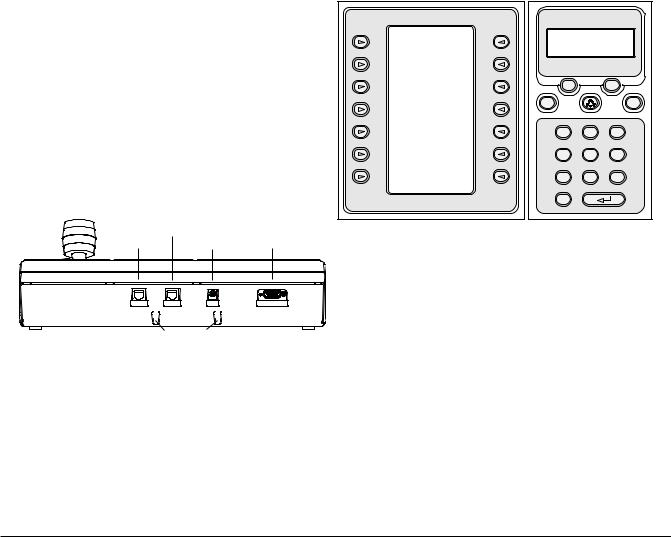
3.1Learning the IntuiKey Components
Learning the IntuiKey Keyboard components is accomplished easily by dividing the keyboard into four separate functional areas as shown in FIGURE 3-1:
•The Status Display
•The Keypad
•The Softkeys and Softkey Display
•The Joystick
SoftKey Display
SoftKey Descriptor |
|
Status Display |
Numeric |
||
|
Entry Cell |
||||
|
|
|
|
Monitor |
Camera |
|
Exit |
|
|
1 |
1 |
|
|
|
|
|
MUX/DVR |
|
^ Up |
Zoom |
Prod |
Mon |
|
|
< Left |
Right > |
Clr |
|
Shot |
|
|
|
|
||
|
v Down |
|
1 |
2 |
3 |
|
|
|
4 |
5 |
6 |
|
|
|
7 |
8 |
9 |
|
|
|
0 |
|
|
SoftKeys |
|
Numeric Keypad |
|||
FIGURE 3-1 |
IntuiKey Components |
|
|||
When a user operation results in an error, the status display changes to Error Code (see SECTION 4.3 for Allegiant Error Messages, SECTION 4.4 for ADIM Error Messages, SECTION 5.3 for Divar Error Messages, and SECTION 6.3 for MUX Error Messages). The display shows the error number, a short description of the error, and the present device under control.
The display reverts to Normal Mode either automatically in two seconds (on its own) or when CLR is pressed.
In Terminal Mode, the third-party software application determines the displayed text via the IntuiKey display screen.
3.1.2 The Keypad
The Keypad includes the five function buttons (located directly below the status display), as well as the numeric keypad.
PROD displays the keyboard’s Product Selection menu. This function key (in conjunction with the Softkeys/Softkey Display) selects the device under the control of the keyboard. The Product Selection menu also provides access to the Keyboard Control menu.
MON functioning depends on the IntuiKey Model and device under control. For KBD-Universal keyboards, MON allows entry of a Monitor Number when controlling an Allegiant Switcher. When controlling a DVR or multiplexer, MON toggles between monitors A and B.
CLR clears any numeric entry and the display reverts to Normal Mode.
 provides acknowledgement of an external alarm/ alert/action condition. When this condition is detected, an audible alarm is enabled, and the
  key flashes red. The key then functions differently depending on the device presently under keyboard control.
NOTE: Refer to SECTION 3.3 for additional information on alarm/alert/action indication and acknowledgement.
Bosch Security Systems | June 11, 2005
 Loading...