


ISP-SM90-120
F.01U.331.565-01 1 © 2016 Bosch Security Systems, Inc.
ISP-SM90-120
(en) Seismic detector
(de) Körperschallmelder
11/2016
1
2
3
4 5
6
F.01U.331.565-01 2 © 2016 Bosch Security Systems, Inc.
7
F.01U.331.565-01 3 © 2016 Bosch Security Systems, Inc.
en
1. EC declaration of conformity
Hereby Bosch Security Systems, Inc. declares that this
equipment type is in compliance with all relevant EU
Directives for CE marking. From 20/04/2016 it is in
compliance with Directive 2014/30/EU (Electromagnetic
Compatibility Directive).
2. Application
The ISP-SM90-120 seismic detector is compatible with both
types of local security network LSNi & LSN and has a loop
connection to the control panel. The detector reliably
detects attempted break-ins to safes, ATMs, night deposits,
lightweight safes, strong rooms and modular steel or
concrete vaults. Intelligent signal processing enables
detection sensitivity to be set individually and therefore
reliably ensures no false alarms. The anti-tamper system for
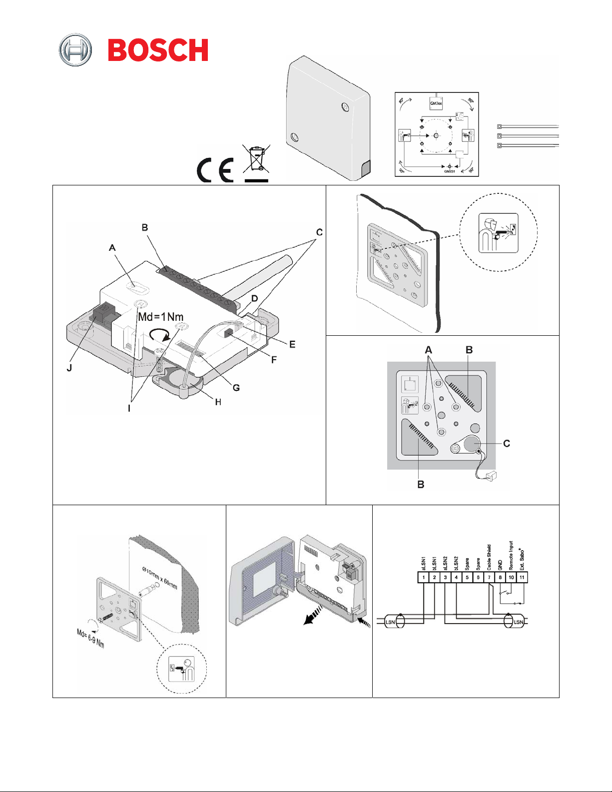
the cover (Fig. 1, item A) and on the back of the ISP-SM90-
120 will detect the opening or the forcible removal of the
detector.
Installation, programming and commissioning must
be performed by specialists.
3. Contents
• 1 x ISP-SM90-120 seismic detector
• 1 x ISP-SM90-120 drill template
• 3 x cable ties
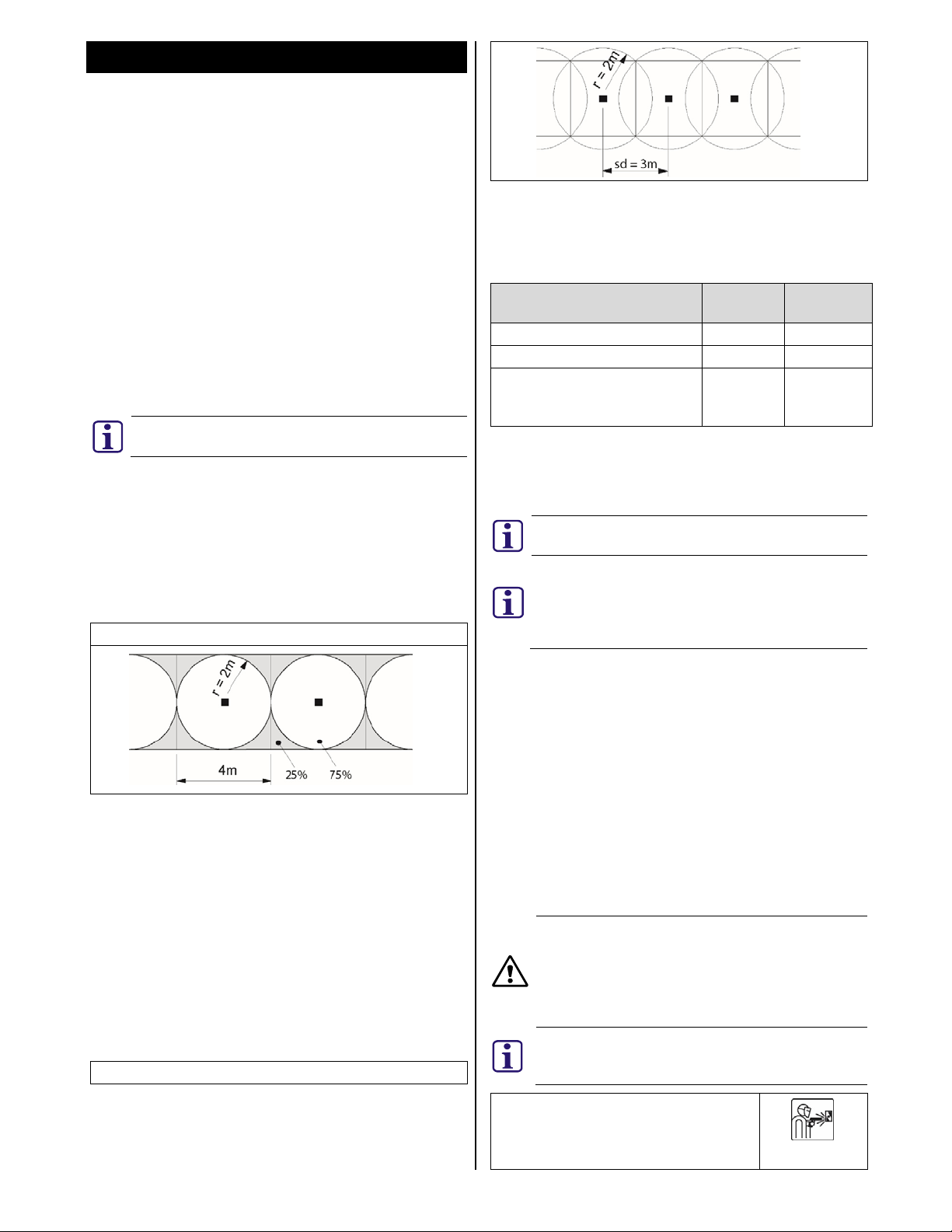
4. Coverage area
The area monitored by the detector is referred to as the
coverage area. It covers the area around the detector with an
operating radius (r).
Detector coverage
Joints in the construction of the vault may impair the
transmission of the signal. Doors must have their own
detector installed to provide the correct coverage.
Tightly sealed corners and edges may reduce the operating
radius (r) by >25%, therefore, corners and edges on steel
vaults must be seamlessly welded. Incorrect positioning can
reduce the coverage area. It is recommended that detectors
are installed on each plane (walls, floor, and ceiling) of the
protected area. Coverage from adjoining planes should not
form part of a comprehensive protection strategy.
4.1. Detector spacing distance
Detectors should be positioned so that they cover the entire
area to be monitored. The distance between detectors is
referred to as the spacing distance (sd).
Detector spacing distance (sd)
To ensure complete coverage of the protected area, the
following formula should be applied to determine the correct
spacing distance between seismic detectors.
Spacing distance (sd) = operating radius(r) x 2 x 0.75
Example:
Material Operating
radius
Spacing
distance
Steel 2m 3m
Concrete 4m 6m
LWS (Systems of armour plating
with synthetic/composite
materials)
1.5m 2.25m
5. Installation
5.1. Direct Installation on steel
The ISP-SM90-120 seismic detector can be installed directly
onto a flat, even metal surface.
Take note of the orientation of the ISP-SM90-120
seismic detector and the required drill pattern.
There must be a direct connection between the
detector and the mounting surface. Paint, varnish,
dirt, silicone or similar materials will impede the
acoustics. Remove these materials from the
mounting location before installation.
Use the ISP-SM90-120 drilling template (provided) to
determine the location of the required holes.
1. Drill 3 x 3.2mm holes, 6mm deep. 2 holes for the
detector and 1 hole for the ISN-GMX-S1 internal test
transmitter (Fig. 1, item H).
2. Remove the drilling template.
3. Thread all holes to M4.
4. Secure the detector and the test transmitter to the
mounting surface.
5.2. Installation on steel using the ISN-GMX-P0 mounting
plate
Use the weld symbol side of the ISN-GMX-P0 mounting plate
(Fig. 2) to install the detector on uneven or reinforced steel
surfaces.
The ISN-GMX-P0 mounting plate can be used for
installing a seismic detector on a steel surface. It is
essential to use the correct side and mounting
methods. The ISN-GMX-P0 displays a detector
symbol to indicate the direction of the cable access
to the detector.
Take note of the orientation of the ISP-SM90-120
seismic detector and the required orientation of
the ISN-GMX-P0 mounting plate.
ISN-GMX-P0 weld symbol
F.01U.331.565-01 4 © 2016 Bosch Security Systems, Inc.
Detector symbol showing cable access at
top
1. With the weld symbol visible, attach the ISN-GMX-P0 to
the mounting surface using two fillet welds as shown
(Fig. 3, item B).
If welding is not possible, use the ISN-GMX-P0 as a drill
template.
• Mark the 3 centrally located countersunk holes (Fig.
3, item A).
• Drill 3 x 3.2mm Ø holes (depth to be determined by
the thickness of the mounting surface).
• Thread to M4.
• Secure the ISN-GMX-P0 using 3 x M4 countersunk
screws (provided with ISN-GMX-P0).
2. Mount the detector on to the ISN-GMX-P0.
3. Mount the ISN-GMX-S1 internal test transmitter on the
designated location on the ISN-GMX-P0 (Fig. 3, item C)
and connect to the detector (Fig. 1, item E).
5.3. Installation on concrete using the ISN-GMX-P0
mounting plate
Use the drill symbol side of the ISN-GMX-P0 mounting plate
(Fig. 4) to install the detector on concrete surfaces.
The ISN-GMX-P0 mounting plate can be used for
installing a seismic detector on a concrete surface.
It is essential to use the correct side and mounting
methods. The ISN-GMX-P0 displays a detector
symbol to indicate the direction of the cable access
to the detector.
Take note of the orientation of the ISP-SM90-120
seismic detector and the required orientation of
the ISN-GMX-P0 mounting plate.
ISN-GMX-P0 drill symbol
Detector symbol showing cable access at
top
1. Use the ISP-SM90-120 drilling template (provided) to
determine the location of the required holes.
2. Drill a 10mm Ø x 60mm hole and insert the steel
expansion plug.
3. Drill a 5mm Ø x >22mm hole and insert the ISN-GMX-S1
brass expansion plug.
When installing on concrete, the ISN-GMX-S1 must
not have any contact with the ISN-GMX-P0
mounting plate. The ISN-GMX-S1 must be attached
to the concrete using the M4 x 21mm screw and the
associated brass expansion plug.
4. Secure the ISN-GMX-P0 to the steel expansion plug with
the M6 x 47mm screw.
5. Secure the ISN-GMX-S1 to the brass expansion plug with
the M4 x 21mm screw.
6. Mount the detector on to the ISN-GMX-P0.
6. Mounting the detector
1. Remove the cover from the detector.
2. Attach the detector to the prepared mounting base using
the two mounting screws (Fig. 1, items I).
3. Remove the cable access skirt (Fig. 5).
4. Wire the connection cables to the terminal (Fig. 1, item
B) as shown in diagram (Fig. 6).
5. Secure the cable to a cable anchor (Fig. 1, items C) with
a cable tie (provided).
6. Connect the accessories and program the detector.
7. Remove the pre-formed cable access points as required
to enable cable access through the skirt (Fig. 5).
8. Replace the cable access skirt.
The cables connected to terminals 8, 10 and 11
must not exceed 3m in length.
The polarity of the LSN Bus must be maintained.
The screen from the LSN cables must be connected
into terminal 7.
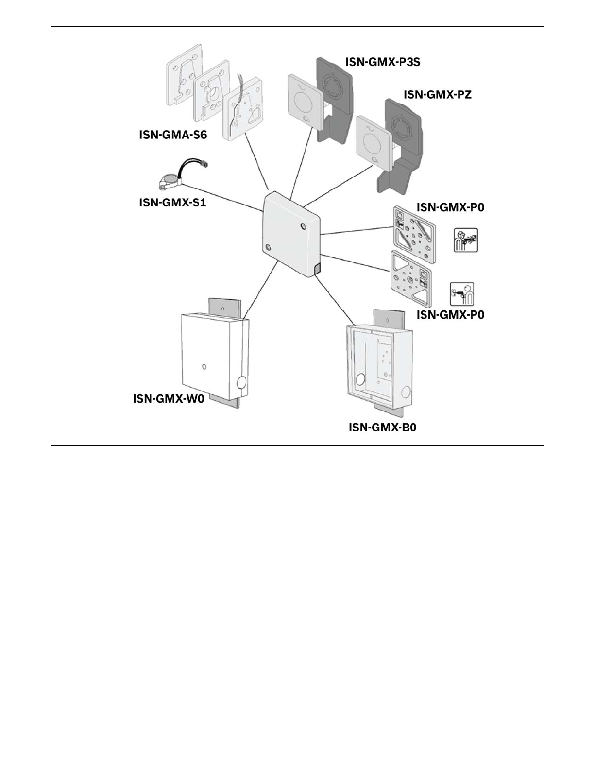
7. Accessories
All of the accessories (Fig. 7) have their own installation
instructions, which are supplied with each accessory. These
installation instructions should be followed for the correct
installation and optimum performance from this seismic
detector. For ordering information, see section 16.
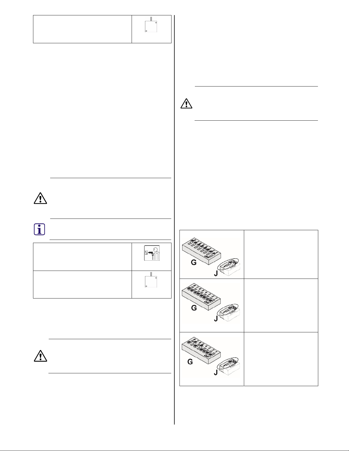
8. Configuration (addressing LSNi/LSN)
ISP-SM90-120 supports LSNi (LSN improved) and LSN (LSN
classic). The detector must be configured using the two DIP
switches (Fig. 1, items G and J) before the power supply is
connected via the LSNi/LSN bus. The DIP switches are used
for configuration and addressing as follows:
• Fig. 1, item G – Addressing
• Fig. 1, item J – Material and coverage application
The following configurations are possible:
LSN application
Fig. 1, item G all in ON
position
Fig. 1, item J in ON position
(default setting)
LSNi application with
automatic addressing
Fig. 1, item G all in OFF
position
Fig. 1, item J in ON position
LSNi application with
manual addressing
Fig. 1, item G set to the
corresponding address (see
the table in the Appendix at
the end of this document).
Fig. 1, item J ON position
 Loading...