Bosch ISC-SK10 Installation Manual

1 | Overview
The ISC-SK10 is an advanced shock sensor designed to monitor doors, windows, safes, and ATM machines. The sensor detects mechanical attacks, such as blasting, hammering, drilling, and sawing.
1 |
7 |
|
6
2
3
4
5
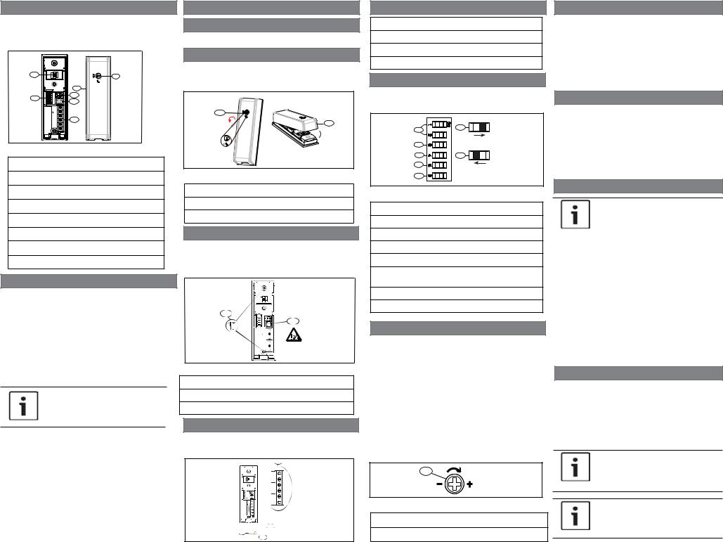
Figure 1.1: Sensor overview
Callout ― Description
1 ― LED
2 ― DIP switches
3 ― Sensitivity adjustment POT
4 ― Tamper switch
5 ― Terminal block
6 ― Cover
7 ― Unlock/lock switch
2 | Installation considerations
Install the ISC-SK10 on a door or window surface, inside a safe, or ATM. Mount the ISC-SK10 on a flat surface such as metal, glass, concrete, or wood surfaces.
When installing the sensor, use the included screws to secure the base to the desired surface, or use an adhesiveAB glue if screws are not suitable. Do not use double-sided tape.
Avoid installing in locations where movement and other manual operations might generate false alarms due to vibrations or accidental contact.
NOTICE!
The ISC-SK10 is intended for indoor use only.
Maximum detection range
Use the different detection ranges that are suitable for the desired surface.
Applications |
Radius (m) |
|
|
Concrete |
1.5 |
|
|
Brick wall |
2.5 |
|
|
Steel |
3 |
|
|
Wood |
3.5 |
|
|
Glass |
3.5 |
|
|
3 | Installation and configuration
3.1 | Hardware installation
Perform the following steps to install the hardware.
3.1.1| Open cover
1.Insert a slotted screwdriver into the Unlock/lock switch and turn counter-clockwise 90° to unlock.
2.Pull apart the cover from the base.
1
2
Figure 3.1: Opening cover
Callout ― Description
1 ― Unlocking the switch
2 ― Pull apart base from cover
3.1.2| Install base
1.Locate desired installation location.
2.Insert supplied screws (two ST2.9x13 mm) into screw slot locations (or use AB glue) to secure the base to the desired surface.
1
2
Figure 3.2: Screw locations
Callout ― Description
1 ― Screw locations
2 ― Tamper
3.1.3| Wiring
1.Insert wiring through the grommet.
2.Fasten wires to terminal block and secure with tie-wrap (included).
1
 2
2  3
3
Figure 3.3: Mounting the module in the enclosure
Callout ― Description
1 ― Terminal block
2 ― Grommet cut-out area
3 ― Wiring
3.2 | Set DIP switches
Refer to Figure 3.4 for the DIP switch locations and settings.
1 |
6 |
|
|
2 |
|
3 |
7 |
4 |
|
5 |
DIP |
Figure 3.4: DIP switch settings
Callout ― Description
1 ― Sensitivity levels (#1 and #2)
2 ― Pulse counting
3 ― Drilling/saw detection (enable/disable)
4 ― LED enable/disable
5 ― Installation mode (this switch enables “Intelligent” mode)
6 ― DIP switch positioning example: ON (open)
7 ― DIP switch positioning example: OFF (closed)
3.2.1| Sensitivity
1. Select the desired sensitivity level (1-4) using DIP switches #1 and #2. Refer to the table below for
settings.
Level |
DIP#1 |
DIP#2 |
|
|
|
High |
ON |
ON |
|
|
|
High-middle |
ON |
OFF |
|
|
|
Low-middle |
OFF |
ON |
|
|
|
Low (default) |
OFF |
OFF |
|
|
|
2. Fine-tune the sensitivity level by turning the POT adjustment clockwise to increase sensitivity, and counter-clockwise to descrease the sensitivity.
1
Figure 3.5: Fine sensitivity adjustment POT
Callout ― Description
1 ― Fine sensitivity adjustment POT
3.2.2| Pulse counting
Select DIP #3 to set the pulse counting adjustment. The sensor generates an alarm when certain pulse countings are reached during the specified time.
DIP #3 |
Pulse counting time(s) |
|
|
ON |
4 |
|
|
OFF |
1 (Default) |
|
|
3.2.3 | Drilling/saw detection
Select DIP #4 to enable or disable the detection of drilling or sawing vibrations. Functionality occurs after sensor is powered up.
DIP #4 |
Drilling/saw detection |
|
|
ON |
Disable |
|
|
OFF |
Enabled (default) |
|
|
3.2.4 | LED descriptions
|
|
NOTICE! |
|
|
The LEDs must be enabled during |
|
|
installation. |
|
|
|
|
|
|
|
DIP #5 |
LED function |
|
|
|
|
ON |
Enabled (default) |
|
|
|
|
OFF |
Disable |
|
|
|
|
|
|
|
LED |
Function |
|
|
|
|
Green |
Indicates an attempt attack was |
|
|
detected. |
|
|
|
|
Red |
Indicates an alarm was generated. |
|
|
|
|
Red (ON |
Indicates there is a sensor fault. |
|
steady) |
|
|
|
|
3.3 | Installation mode
Select DIP #6 to choose between manual or intelligent mode.
DIP #6 |
Installation mode |
|
|
ON |
Intelligent |
|
|
OFF |
Manual (default) |
|
|
NOTICE!
Enable the LED and cycle power on the system before applying the intelligent installation mode.
NOTICE!
Manual installation is active 20 min after powering up the system.
 Loading...