


 Loading...
Conettix Ethernet Communication Module
B426
en Installation and Operation Guide

Conettix Ethernet Communication |
Table of Contents | en |
3 |
|
Module |
|||
|
|
||
|
|
|
Table of contents
1 |
Safety |
4 |
2 |
Introduction |
5 |
2.1 |
About documentation |
5 |
2.2 |
Bosch Security Systems, Inc. product manufacturing dates |
5 |
2.3 |
Installation workflow |
6 |
3 |
|
|
System overview |
7 |
|
3.1 |
Overview |
8 |
3.2 |
Bus address settings |
9 |
4 |
|
|
Installation |
10 |
|
4.1 |
Mount the module in the enclosure |
10 |
4.2 |
Mount and wire the tamper switch (optional) |
10 |
4.3 |
Wire to the control panel |
11 |
5 |
|
|
Configuration |
13 |
|
5.1 |
Plug and Play configuration for SDI2 control panels |
13 |
5.2 |
Plug and Play configuration for SDI or option bus control panels |
13 |
5.3 |
Web-based configuration |
13 |
5.3.1 |
Web-based configuration log in and use |
14 |
5.3.2 |
Device Information (home) page |
15 |
5.3.3 |
Change and save settings using the web |
15 |
5.3.4 |
Basic Network Settings page |
16 |
5.3.5 |
Advanced Network Settings page |
20 |
5.3.6 |
Panel Address Settings page |
21 |
5.3.7 |
Encryption and Security Settings page |
23 |
5.3.8 |
Maintenance page |
24 |
5.3.9 |
Factory Default page |
26 |
5.3.10 |
Firmware Update page |
27 |
5.3.11 |
Exiting the web-based configuration pages |
28 |
6 |
|
|
Maintenance and troubleshooting LEDs |
30 |
|
6.1 |
Show the firmware version |
31 |
7 |
|
|
Specifications and certifications |
33 |
|
7.1 |
Technical specifications |
33 |
8 |
|
|
Appendix |
35 |
|
8.1 |
Module hostname |
35 |
8.2 |
Module IP address |
35 |
8.2.1 |
Use DHCP to look up the IP address of a network-connected module |
35 |
8.2.2 |
Use an SDI/SDI2 keypad to discover the IP address of a module |
35 |
8.2.3 |
Use Auto IP with a directly connected module |
36 |
Bosch Security Systems, Inc. |
Installation and Operation Guide |
2015.07 | 06 | F.01U.266.226 |

4 |
en | Safety |
Conettix Ethernet Communication |
|
Module |
|||
|
|
||
|
|
|
1 Safety
ESD Precaution
Please note that the B426 board comes without any case/box and all components are exposed for finger touches - therefore extra attention must be paid to ESD (electrostatic discharge) precaution. Make sure there is no static interference when using the board. Appropriate ESD protections must be taken and wearing electrostatic equipment is recommended, such as antistatic wrist strap.
ESD damage can range from subtle performance degradation to complete device failure. Precision integrated circuits may be more susceptible to damage because very small parametric changes could cause the device not to meet its published specifications.
Warning!
Failure to follow these instructions can result in a failure to initiate alarm conditions. Bosch
!Security Systems, Inc. is not responsible for improperly installed, tested, or maintained devices. Follow these instructions to avoid personal injury and damage to the equipment.
Notice!
Inform the operator and the local authority having jurisdiction (AHJ) before installing the module in an existing system.
Disconnect all power to the control panel before installing the module. Before installing a B426, refer to Technical specifications, page 33.
2015.07 | 06 | F.01U.266.226 |
Installation and Operation Guide |
Bosch Security Systems, Inc. |
Conettix Ethernet Communication |
Introduction | en |
5 |
|
Module |
|||
|
|
||
|
|
|
2 |
Introduction |
|
This section includes basic documentation information and an installation checklist. |
2.1 |
About documentation |
|
Copyright |
|
This document is the intellectual property of Bosch Security Systems, Inc. and is protected by |
|
copyright. All rights reserved. |
|
Trademarks |
|
All hardware and software product names used in this document are likely to be registered |
|
trademarks and must be treated accordingly. |
2.2 |
Bosch Security Systems, Inc. product manufacturing dates |
|
Use the serial number located on the product label and refer to the Bosch Security Systems, |
Inc. website at http://www.boschsecurity.com/datecodes/.
The following image shows an example of a product label and highlights where to find the manufacturing date within the serial number.
|
|
|
|
|
|
|
|
|
|
|
|
|
|
|
|
|
|
|
|
|
|
|
|
|
|
|
|
|
|
|
|
|
|
|
|
|
|
|
|
|
|
|
|
|
|
|
|
|
|
|
|
|
|
|
|
|
|
|
|
|
|
|
|
|
|
|
|
|
|
|
|
|
|
|
|
|
|
|
|
|
|
|
|
|
|
|
|
|
|
|
|
|
|
|
|
|
|
|
|
|
|
|
|
|
|
|
|
|
|
|
|
|
|
|
|
|
|
|
|
|
|
|
|
|
|
|
|
|
|
|
|
|
|
|
|
|
|
|
|
|
|
|
|
|
|
|
|
|
|
|
|
|
|
|
|
|
|
|
|
|
|
|
|
|
|
|
|
|
|
|
|
|
|
|
|
|
|
|
|
|
|
|
|
|
|
|
|
|
|
|
|
|
|
|
|
|
|
|
|
|
|
|
|
|
|
|
|
|
|
|
|
|
|
|
|
|
|
|
|
|
|
|
|
|
|
|
|
|
|
|
|
|
|
|
|
|
|
|
|
|
|
|
|
|
|
|
|
|
|
|
|
|
|
|
|
|
|
|
|
|
|
|
|
|
|
|
|
|
|
|
|
|
|
|
|
|
|
|
|
|
|
|
|
|
|
|
|
|
|
|
|
|
|
|
|
|
|
|
|
|
|
|
|
|
|
|
|
|
|
|
|
|
|
|
|
|
|
|
|
|
|
|
|
|
|
|
|
|
|
|
|
|
|
|
|
|
|
|
|
|
|
|
|
|
|
|
|
|
|
|
|
|
|
|
|
|
|
|
|
|
|
|
|
|
|
|
|
|
|
|
|
Bosch Security Systems, Inc. |
|
|
|
|
|
|
|
|
|
|
|
|
|
Installation and Operation Guide |
2015.07 | 06 | F.01U.266.226 |
|||||||||||||||

6 |
en | Introduction |
Conettix Ethernet Communication |
|
Module |
|||
|
|
||
|
|
|
2.3 Installation workflow
To install and configure the module, use the workflow below and follow in sequential order from top to bottom, checking off each box as you complete a step.
Caution!
!Always power down the control panel when connecting a module. To power down the control panel, unplug the transformer and disconnect the battery.
 Plan the installation. Refer to System overview, page 7.
 Set the address switch. Refer to Bus address settings, page 9.
 Install the module. Refer to Mount the module in the enclosure, page 10, Mount and wire the tamper switch (optional), page 10, and Wire to the control panel, page 11.

 Configure the module. Refer to Plug and Play configuration for SDI2 control panels, page 13, or Plug and Play configuration for SDI or option bus control panels, page 13, or Web-based configuration, page 13.

 Verify operation using the LEDs. Refer to Maintenance and troubleshooting LEDs, page 30.
2015.07 | 06 | F.01U.266.226 |
Installation and Operation Guide |
Bosch Security Systems, Inc. |
Conettix Ethernet Communication |
System overview | en |
7 |
|
Module |
|||
|
|
||
|
|
|
3 System overview
Use the B426 for bi-directional communication over an Ethernet network.
1
2 |
4 |
3
12
|
9 |
11 |
|
|
|
|
|
|
|||
|
|
|
5 |
||
|
|
|
|
||
10 |
|
|
|
8 |
|
|
|
|
|
||
|
|
|
|
||
|
|
|
|||
|
|
|
6 |
||
|
|
|
7 |
|
|
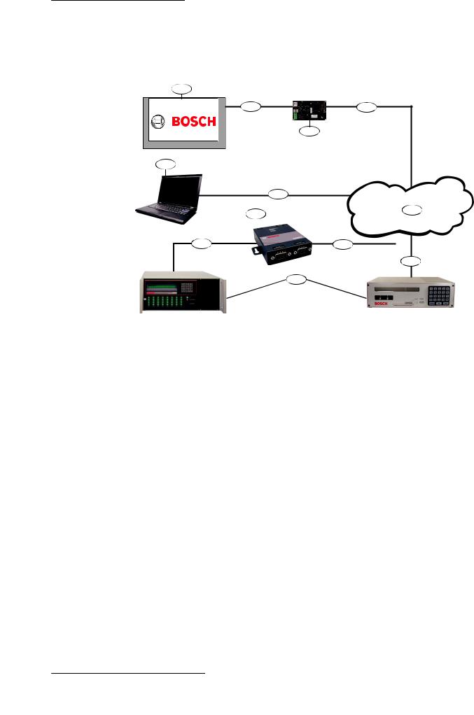
Figure 3.1: B426 system connections overview
Callout Description |
Callout Description |
|
|
|
|
1 |
Compatible Bosch control panel |
7 Conettix D6100i Communications Receiver/Gateway and/or |
|
|
Conettix D6600 Communications Receiver/Gateway (Conettix |
|
|
D6600 Communications Receiver/Gateway requires 8, 9, and 10) |
|
|
|
2 |
Data bus connection between the control |
8 Ethernet network connection to the Ethernet adapter |
panel and the module |
(D6680/ITS-D6682/ITS-D6686) (ITS-D6682 shown) Ethernet |
|
|
|
Network Adapter |
|
|
|
3 |
B426 |
9 Conettix Ethernet Network Adapter (ITS-D6682 shown) |
|
|
|
4 |
Ethernet connection between module and |
10 Connection from ITS-D6682 to the COM4 Port on the |
Ethernet network |
Conettix D6600 Communications Receiver/Gateway |
|
|
|
|
5 |
Ethernet network, Local Area Network |
11 Ethernet network connection between the host computer |
(LAN), Metropolitan AreaNetwork (MAN), Wide |
Ethernet network interface card (NIC) and the Ethernet network |
|
Area Network (WAN), or Internet |
|
|
|
|
|
6 |
Ethernet network connection to the |
12 Host PC running Remote Programming Software, |
D6100i Communications Receiver (D6100i/ |
Automation, or the Conettix D6200 Programming/Administration |
|
D6100IPv6) |
Software |
|
|
|
|
Bosch Security Systems, Inc. |
Installation and Operation Guide |
2015.07 | 06 | F.01U.266.226 |
8 |
en | System overview |
Conettix Ethernet Communication |
|
Module |
|||
|
|
||
|
|
|
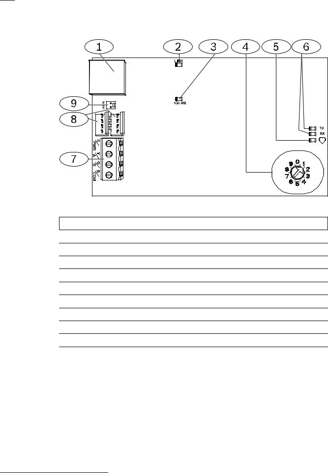
B426 module overview
Figure 3.2: B426 Conettix Ethernet Communication Module
Callout Description
1 Ethernet RJ-45 port
2 Yellow LINK LED
3 Green 100MB LED
4 Address switch
5 Heartbeat LED
6 TX and RX LEDs
7 Terminal strip (to control panel)
8 Interconnect wiring connectors (to control panel or other compatible modules)
9 Tamper switch connector
3.1 Overview
The B426 Conettix Ethernet Communication Module is a four-wire powered SDI, SDI2, or option bus device that provides two-way communication with compatible control panels over IPv6 or IPv4 Ethernet networks.
The B426 on-board switch determines the bus address of the device. Perform configuration of the B426 through the B426 configuration web pages. On SDI2 control panels, configuration can also be done on the keypad or through Remote Programming Software (RPS). The B426 Conettix Ethernet Communication Module is compatible with IPv6.
2015.07 | 06 | F.01U.266.226 |
Installation and Operation Guide |
Bosch Security Systems, Inc. |

Conettix Ethernet Communication |
System overview | en |
9 |
|
Module |
|||
|
|
||
|
|
|
3.2 Bus address settings
The address switch determines the bus type and the module’s address on the bus. The control panel uses the address for communications. Use a slotted screwdriver to set the address switch.
Notice!
The module reads the address switch setting only during module power up. If you change the setting after you apply power to the module, you must cycle the power to the module in order for the new setting to take effect.
The B426 address switch provides the value for the module's address. The figure below shows the address switch setting for address 1. Refer to the following table for panel-specific settings.
Figure 3.3: Address switch set to address 1
Control panels |
Switch |
Control |
Bus type |
|
|
position |
panel |
|
|
|
|
address |
|
|
|
|
|
|
|
B9512G/B8512G, B5512/ |
1 |
1 |
SDI2 |
Automation, Remote |
B4512/B3512 GV4, |
|
|
|
Programming or |
Solution 2000/3000 |
|
|
|
Reporting |
|
|
|
|
|
B9512G/B8512G, GV4, |
2 |
2 |
|
|
Solution 2000/3000 |
|
|
|
|
|
|
|
|
|
GV4, GV3, GV2, D9412G/ |
3 |
80 |
SDI |
Automation |
D7412G/D7212G v6.3 or |
|
|
|
|
higher |
|
|
|
|
|
|
|
|
|
GV4, GV3, GV2, D9412G/ |
4 |
88 |
|
Reporting or Remote |
D7412G/D7212G v6.3 or |
|
|
|
Programming |
higher |
|
|
|
|
|
|
|
|
|
GV4, GV3 |
5 |
92 |
|
|
|
|
|
|
|
DS7240V2, DS7220V2, Easy |
6 |
134 |
Option |
|
Series V3+, AMAX |
|
|
|
|
|
|
|
|
|
DS7400Xi |
7 |
13 |
|
|
|
|
|
|
|
DS7400Xi |
8 |
14 |
|
Reporting |
|
|
|
|
|
FPD-7024 |
9 |
250 |
|
Reporting or Remote |
|
|
|
|
Programming |
|
|
|
|
|
Table 3.1: B426 address switch settings |
|
|
|
|
Bosch Security Systems, Inc. |
Installation and Operation Guide |
2015.07 | 06 | F.01U.266.226 |
10 en | Installation |
Conettix Ethernet Communication |
|
Module |
||
|
||
|
|
4 |
Installation |
|
After you set the address switch for the proper address, install the module in the enclosure |
|
and then wire the module to the control panel and to the Ethernet connection. |
4.1 |
Mount the module in the enclosure |
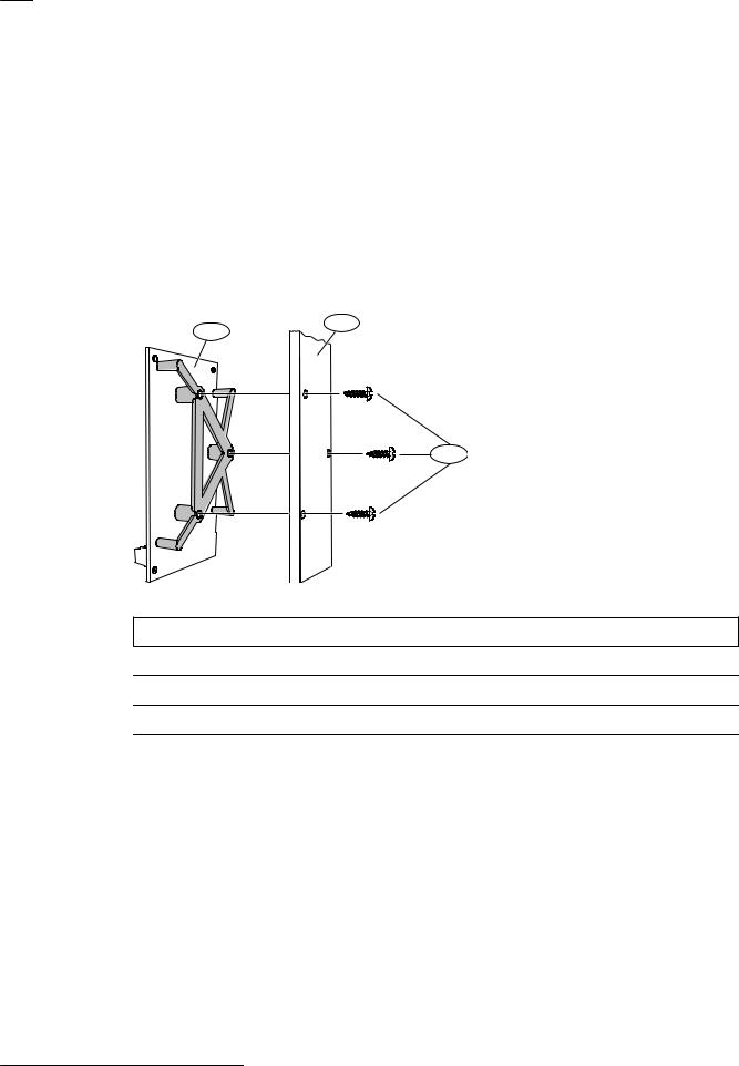
Mount the B426 into the enclosure’s 3-hole mounting pattern using the supplied mounting screws and mounting bracket.
For UL certified systems, you must mount the module in the control panel enclosure or in a UL listed enclosure (for example, the D8103 Universal Enclosure).
House all communicators in tampered enclosures, compliant with the following clauses within Standard CAN/ULC-S304-06: 5.2.6; 5.2.9; 5.2.10 and 5.2.15.
2
1
3
Figure 4.1: Mounting the module
Callout Description
1 B426 with mounting bracket installed
2 Enclosure
3 Mounting screws (3)
4.2 Mount and wire the tamper switch (optional)
For B9512G/B8512G, B5512/B4512/B3512, and GV4 v.2xx control panels, you can connect an enclosure door tamper switch for one module in an enclosure.
Installing the optional tamper switch for use with a B426:
1.Mount the ICP-EZTS Cover and Wall Tamper Switch (P/N: F01U009269) into the enclosure’s tamper switch mounting location. For complete instructions, refer to the Cover and Wall Tamper Switch (ICPEZTS) Installation Guide (P/N: F01U003734).
2.Plug the tamper switch wire onto the module’s tamper switch connector. For the tamper switch connector location, refer to B426 module overview, page 8.
2015.07 | 06 | F.01U.266.226 |
Installation and Operation Guide |
Bosch Security Systems, Inc. |
Conettix Ethernet Communication |
Installation | en 11 |
|
Module |
||
|
||
|
|
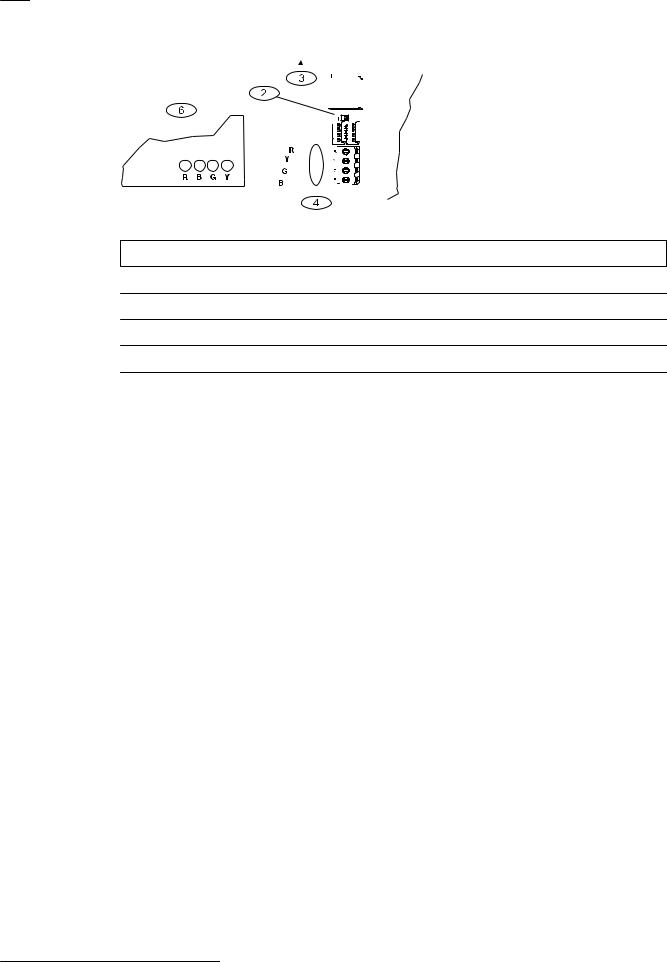
4.3 Wire to the control panel
When you wire a B426 to an SDI or SDI2 control panel, you can use either the module's terminal strip labeled R, Y, G, B (PWR, A, B, COM) or the module's interconnect wiring connectors (wire included). The figure below indicates the location of both the terminal strip and the interconnect wiring connectors on the module.
Notice!
Remove all power (AC and Battery) before making any connections. Failure to do so may result in personal injury and/or equipment damage.
Notice!
Use either the terminal strip wiring or interconnect cable to wire to the control panel. Do not use both. When connecting multiple modules, you can combine terminal strip and interconnect wiring connectors in series.
Run the wiring connections from the module to the data bus terminals on the compatible control panel. Connect the Ethernet cable to the Ethernet port on the module.
Figure 4.2: Using terminal strip or interconnect cable wiring (GV4 control panel shown)
Callout Description
1 SDI2 control panel. For SDI control panels, wire R, Y, G, B to the SDI bus.
2 Module
3 To Ethernet network
4 Terminal strip wiring
5 Interconnect cable (P/N: F01U079745) (included)
Bosch Security Systems, Inc. |
Installation and Operation Guide |
2015.07 | 06 | F.01U.266.226 |
12 en | Installation |
|
|
|
|
|
|
|
|
|
Conettix Ethernet Communication |
|||||||||||||||||||||||||||||||||||||||
|
|
|
|
|
|
|
|
|
Module |
||||||||||||||||||||||||||||||||||||||||
|
|
|
|
|
|
|
|
|
|
|
|
|
|
|
|
|
|
|
|
|
|
|
|
|
|
|
|
|
|
|
|
|
|
|
|
|
|
|
|
|
|
|
|
|
|
|
|
|
|
|
|
|
|
|
|
|
|
|
|
|
|
|
|
|
|
|
|
|
|
|
|
|
|
|
|
|
|
|
|
|
|
|
|
|
|
|
|
|
|
|
|
|
|
|
|
|
|
|
|
|
|
|
|
|
|
|
|
|
|
|
|
|
|
|
|
|
|
|
|
|
|
|
|
|
|
|
|
|
|
|
|
|
|
|
|
|
|
|
|
|
|
|
|
|
|
|
|
|
|
|
|
|
|
|
|
|
|
|
|
|
|
|
|
|
|
|
|
|
|
|
|
|
|
|
|
|
|
|
|
|
|
|
|
|
|
|
|
|
|
|
|
|
|
|
|
|
|
|
|
|
|
|
|
|
|
|
|
|
|
|
|
|
|
|
|
|
|
|
|
|
|
|
|
|
|
|
|
|
|
|
|
|
|
|
|
|
|
|
|
|
|
|
|
|
|
|
|
|
|
|
|
|
|
|
|
|
|
|
|
|
|
|
|
|
|
|
|
|
|
|
|
|
|
|
|
|
|
|
|
|
|
|
|
|
|
|
|
|
|
|
|
|
|
|
|
|
|
|
|
|
|
|
|
|
|
|
|
|
|
|
|
|
|
|
|
|
|
|
|
|
|
|
|
|
|
|
|
|
|
|
|
|
|
|
|
|
|
|
|
|
|
|
|
|
|
|
|
|
|
|
|
|
|
|
|
|
|
|
|
|
|
|
|
|
|
|
|
|
|
|
|
|
|
|
|
|
|
|
|
|
|
|
|
|
|
|
|
|
|
|
|
|
|
|
|
|
|
|
|
|
|
|
|
|
|
|
|
|
|
|
|
|
|
|
|
|
|
|
|
|
|
|
|
|
|
|
|
|
|
|
|
|
|
|
|
|
|
|
|
|
|
|
|
|
|
|
|
|
|
|
|
|
|
|
|
|
|
|
|
|
|
|
|
|
|
|
|
|
|
|
|
|
|
|
|
|
|
|
|
|
|
|
|
|
|
|
|
|
|
|
|
|
|
|
|
|
|
|
|
|
|
|
|
|
|
|
|
|
|
|
|
|
|
|
|
|
|
|
|
|
|
|
|
|
|
|
|
|
|
|
|
|
|
|
|
|
|
|
|
|
|
|
|
|
|
|
|
|
|
|
|
|
|
|
|
|
|
|
|
|
|
|
|
|
|
|
|
|
|
|
|
|
|
|
|
|
|
|
|
|
|
|
|
|
|
|
|
|
|
|
|
|
|
|
|
|
|
|
|
Figure 4.3: Wiring to an option bus terminal strip
Callout Description
1 Compatible control panel (FPD-7024 control panel shown)
2 Module
3 To Ethernet network
4 Terminal strip wiring
For complete wiring instructions, refer to the control panel documentation.
2015.07 | 06 | F.01U.266.226 |
Installation and Operation Guide |
Bosch Security Systems, Inc. |
Loading...