


 Loading...
Bosch B465, B465-MR-120WI, B465-MR-1640, B465-MRC-120WI, B465-MRC-1640 Installation Manual
...
Conettix Universal Dual Path Communicator
B465
en Installation and Operation Guide

Conettix Universal Dual Path |
Table of Contents | en |
3 |
|
Communicator |
|||
|
|
||
|
|
|
Table of contents
1 |
Safety |
5 |
2 |
Introduction |
6 |
2.1 |
About documentation |
6 |
2.2 |
Bosch Security Systems, Inc. product manufacturing dates |
7 |
2.3 |
Installation workflow |
7 |
3 |
|
|
System overview |
9 |
|
3.1 |
Module overview |
9 |
3.2 |
PSTN input reporting format compatibility |
13 |
3.3 |
Digital communication |
13 |
3.3.1 |
Telephone line voltage |
13 |
3.4 |
B46 overview (optional) |
14 |
4 |
|
|
Installation |
16 |
|
4.1 |
Remove enclosure knockouts |
16 |
4.2 |
Mount the enclosure |
17 |
4.3 |
Insert wiring label |
18 |
4.4 |
Insert D101 lock (optional) |
19 |
4.5 |
Insert B46 LED cover (optional) |
19 |
4.6 |
Install the module |
20 |
4.6.1 |
Mount the module |
20 |
4.6.2 |
Mount the B46 (optional) |
22 |
4.6.3 |
Connect earth ground |
24 |
4.7 |
Insert the cellular communication module (optional) |
25 |
4.8 |
Wiring installation |
25 |
4.8.1 |
System wiring |
25 |
4.8.2 |
Control panel to dialer capture wiring |
27 |
4.8.3 |
Control panel to dry contact wiring |
27 |
4.8.4 |
B46 module wiring (optional) |
28 |
4.8.5 |
Input loop wiring |
29 |
4.8.6 |
Output wiring |
31 |
4.8.7 |
Input power supply wiring |
32 |
4.8.8 |
D1640-120WI transformer wiring (optional) |
34 |
4.8.9 |
12 VDC battery wiring |
34 |
5 |
|
|
Communications |
39 |
|
5.1 |
IP communication |
39 |
5.1.1 |
On-board Ethernet connection |
39 |
5.1.2 |
Conettix Plug-in Cellular Communicators |
40 |
5.1.3 |
Compatible receivers for IP communication |
40 |
5.1.4 |
Communication routing |
41 |
6 |
|
|
Configuration |
43 |
|
6.1 |
Use USB to configure the B465 |
43 |
6.2 |
Install a serial communication program |
44 |
6.3 |
Log into the USB interface |
47 |
6.3.1 |
USB Main menu screen |
48 |
6.3.2 |
USB menu structure |
50 |
6.3.3 |
USB menu options |
52 |
6.3.4 |
Status menu |
54 |
6.3.5 |
Advanced Status menu |
57 |
Bosch Security Systems, Inc. |
Installation and Operation Guide |
2015.09 | 03 | F.01U.311.207 |

4 |
en | Table of Contents |
Conettix Universal Dual Path |
||
Communicator |
||||
|
|
|
||
|
|
|
|
|
6.3.6 |
|
Standard Communication Configuration |
59 |
|
6.3.7 |
|
Advanced Communication Configuration |
60 |
|
6.3.8 |
|
System Configuration |
63 |
|
6.3.9 |
|
Input Configuration |
67 |
|
6.3.10 |
Relay Configuration |
68 |
||
6.3.11 |
Maintenance |
70 |
||
6.4 |
|
Firmware Update page |
71 |
|
7 |
|
|
|
|
|
Maintenance and troubleshooting |
75 |
||
7.1 |
|
LED status indicators |
75 |
|
7.2 |
|
Show the firmware version |
81 |
|
7.3 |
|
Diagnostic log |
82 |
|
7.4 |
|
Understanding network polling |
82 |
|
7.5 |
|
Troubleshooting procedures |
82 |
|
7.5.1 |
|
No power on the B465 |
82 |
|
7.5.2 |
|
Initialization - cellular |
82 |
|
7.5.3 |
|
Hardware |
83 |
|
7.5.4 |
|
Firmware |
83 |
|
7.5.5 |
|
SIM card |
83 |
|
7.5.6 |
|
PIN code |
83 |
|
7.5.7 |
|
Cellular network registration |
84 |
|
7.5.8 |
|
USB COM port error |
84 |
|
7.6 |
|
Testing the system |
85 |
|
8 |
|
|
|
|
|
Specifications and certifications |
87 |
||
8.1 |
|
Technical specifications |
87 |
|
8.1.1 |
|
B465 power supply specifications |
88 |
|
8.1.2 |
|
Application environment |
89 |
|
8.1.3 |
|
Standby battery requirements and calculations |
90 |
|
8.1.4 |
|
24 VDC Input power requirements |
91 |
|
8.1.5 |
|
Required programming to meet UL 864 |
91 |
|
8.1.6 |
|
Required programming to meet ULC-S304 |
92 |
|
8.1.7 |
|
Compatible UL listed components |
93 |
|
8.2 |
|
Certifications |
96 |
|
2015.09 | 03 | F.01U.311.207 |
Installation and Operation Guide |
Bosch Security Systems, Inc. |

Conettix Universal Dual Path |
Safety | en |
5 |
|
Communicator |
|||
|
|
||
|
|
|
1 Safety
ESD precaution
Please note that the B465 and optional cellular communication modules come in a plastic bags, and are protected from ESD. All plug-in cellular communicator components may potentially be exposed to finger touches - therefore extra attention must be paid to ESD (electrostatic discharge) precaution. Make sure there is no static interference when using the board. Appropriate ESD protections must be taken and wearing electrostatic equipment is recommended, such as anti-static wrist strap.
ESD damage can range from subtle performance degradation to complete device failure. Precision integrated circuits may be more susceptible to damage because very small parametric changes could cause the device not to meet its published specifications.
Warning!
Failure to follow these instructions can result in a failure to initiate alarm conditions. Bosch
!Security Systems, Inc. is not responsible for improperly installed, tested, or maintained devices. Follow these instructions to avoid personal injury and damage to the equipment.
Notice!
Inform the operator and the local authority having jurisdiction (AHJ) before installing the module in an existing system.
Disconnect all power to the control panel before installing the module.
Bosch Security Systems, Inc. |
Installation and Operation Guide |
2015.09 | 03 | F.01U.311.207 |

6 |
en | Introduction |
Conettix Universal Dual Path |
|
Communicator |
|||
|
|
||
|
|
|
2 Introduction
The B465 Conettix Universal Dual Path Communicator (referred to as the B465) links the PSTN digital dialer and/or dry contact inputs from a control panel to an IP connection (Ethernet or Cellular) to the D6600 or D6100i Communication Receiver/Gateway through an internet connection.
The need to reprogram the control panel’s automation from PSTN to IP operations is not required when the B465 is installed. This conversion occurs within the Bosch Conettix Receiver. All messages generated internally by the B465 are sent to the central station in Contact ID format.
When the control panel’s PSTN dialer sends a message, the module simulates a public switched telephone network (PSTN) connection to the central station. The module decodes the control panel’s PSTN dialer report and sends the decoded reports by IP connection using Bosch’s Conetix Protocol to the Conettix D6600, D6100IPv6, or D6100i Communication Gateway/Receiver (referred to as the receiver). When the receiver acknowledges receipt of the message, it sends an acknowledgement report to the module which in turn sends an acknowledgement to the connected control panel. This process maintains true end-to-end security.
The module has the following connections:
–Ethernet connects to the network
–dry contact programmable inputs (4x)
–3 programmable relay outputs, if necessary, to indicate conditions to the control panel, if required
–Control panel Phone line inputs to the B465 (2x).
–B44x Cellular Module (optional)
–B46 External Annunciator (optional)
2.1 About documentation
Copyright
This document is the intellectual property of Bosch Security Systems, Inc. and is protected by copyright. All rights reserved.
Trademarks
All hardware and software product names used in this document are likely to be registered trademarks and must be treated accordingly.
Bosch includes the open source software modules listed below in the firmware for this control panel. The inclusion of these modules does not limit the Bosch warranty.
Software acknowledgement
Time routines
Copyright © 2002 Michael Ringgaard. All rights reserved.
This software [Time routines] is provided by the copyright holders and contributors "as is" and any express or implied warranties, including, but not limited to, the implied warranties of merchantability and fitness for a particular purpose are disclaimed. In no event shall the copyright owner or contributors be liable for any direct, indirect, incidental, special, exemplary, or consequential damages (including, but not limited to, procurement of substitute goods or services; loss of use, data, or profits; or business interruption) however caused and on any theory of liability, whether in contract, strict liability, or tort (including negligence or otherwise) arising in any way out of the use of this software, even if advised of the possibility of such damage.
Redistribution and use in source and binary forms, with or without modification, are permitted provided that the following conditions are met:
2015.09 | 03 | F.01U.311.207 |
Installation and Operation Guide |
Bosch Security Systems, Inc. |

Conettix Universal Dual Path |
Introduction | en |
7 |
|
Communicator |
|||
|
|
||
|
|
|
|
1. |
Redistributions of source code must retain the above copyright notice, this list of |
|
|
|
conditions and the following disclaimer. |
|
|
2. |
Redistributions in binary form must reproduce the above copyright notice, this list of |
|
|
|
conditions and the following disclaimer in thedocumentation and/or other materials |
|
|
|
provided with the distribution. |
|
|
3. |
Neither the name of the project nor the names of its contributors may be used to endorse |
||
|
or promote products derived from this softwarewithout specific prior written permission. |
||
RSA data security |
|
||
Copyright © 1991-2, RSA Data Security, Inc. Created 1991. All rights reserved. The "RSA Data |
|||
Security, Inc. MD5 Message-Digest Algorithm" is included in the module firmware. |
|
||
RSA Data Security, Inc. makes no representations concerning either the merchantability of this |
|||
software or the suitability of this software for any particular purpose. It is provided "as is" |
|
||
without express or implied warranty of any kind. |
|
||
2.2 |
Bosch Security Systems, Inc. product manufacturing dates |
|
Use the serial number located on the product label and refer to the Bosch Security Systems, |
|
Inc. website at http://www.boschsecurity.com/datecodes/. |
2.3 |
Installation workflow |
|
To install and configure the module, use the workflow below and follow in sequential order |
|
from top to bottom, checking off each box as you complete a step. |
Caution!
!Always power down the B465 when connecting a module. To power down the B465, unplug the transformer and disconnect the battery.
Bosch Security Systems, Inc. |
Installation and Operation Guide |
2015.09 | 03 | F.01U.311.207 |

8 |
en | Introduction |
Conettix Universal Dual Path |
|
Communicator |
|||
|
|
||
|
|
|
Installation workflow checklist
 Plan the installation of the B465
 Unpack the device contents
 Power down the system
 Install the enclosure (Refer to Mount the enclosure, page 17)
 Mount the B465 into the enclosure (Refer to Install the module, page 20)
 Mount the B46 (module and cover) into the enclosure (Refer Insert B46 LED cover (optional), page 19)
 Insert the desired plug-in communicator into the B465 (if required) (Refer to Insert the cellular communication module (optional), page 25)
 Wire the B465 to a compatible control panel (Refer to Wiring installation, page 25)
 Power up the system
 Install a communication program (if required) (Refer to Communications, page 39)
 Configure the communication module
 Verify LED activity (Refer to LED status indicators, page 75)
 Review signal strength on the cellular communicator (if required). Refer to your cellular communicator Installation Guide for more information on signal strength.
 Installation is complete
2015.09 | 03 | F.01U.311.207 |
Installation and Operation Guide |
Bosch Security Systems, Inc. |
Conettix Universal Dual Path |
System overview | en |
9 |
|
Communicator |
|||
|
|
||
|
|
|
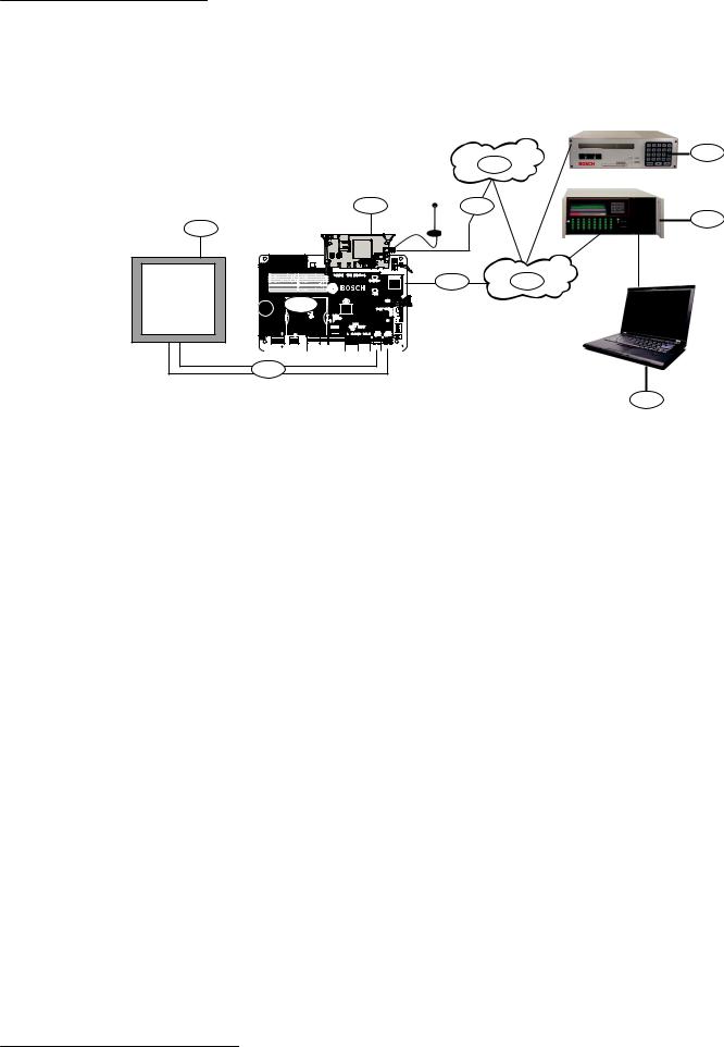
3 System overview
Refer to the figure below for the complete module configuration.
9
8
4 7
10
1
|
Y |
|
|
|
MODULE |
|
|
RELEASE |
|
ETHERNET |
|
|
100BASE-T |
ETHERNET |
|
LINK |
|
3 |
USB |
|
SYSTEM TROUBLE |
TRBL |
|
|
TX |
TX |
SDI2 |
RX |
|
RX |
DEVICE BUS |
AC |
|
AC |
|
R |
Y |
G |
B |
|
|
BATTERY |
BAT |
|
|
|
|
|
INPUTS |
PANEL |
PANEL |
EXTERNAL |
ANNUNC |
|
|
|
|
|
2.2 K |
END OF |
||||
|
|
|
|
LINE RESISTORS |
|
|
|
|
|
18 VAC |
BATTERY |
|
|
1 COM 2 |
3 COM 4 |
LINE 1 |
LINE 2 |
TMPR |
|
|
|
|
|
|
|
|
|
|
|
|
|
|
|
|
|
|
18VAC |
+ BAT - |
NO C NC |
C NO |
C NO |
12V 1 COM 2 3 COM 4 PNL LINE 1 PNL LINE 2 |
|
|
|
RELAY 1 |
RELAY 2 |
RELAY 3 |
AUX COM |
|
2
Figure 3.1: System connection overview
5 6
11
Callout Description |
Callout Description |
||
|
|
|
|
1 |
Intrusion/fire control panel |
7 |
Cellular communication to cellular carrier |
|
|
|
|
2 |
Phone line connections (phone line 1 |
8 |
Cellular carrier network |
and phone line 2) |
|
|
|
|
|
|
|
3 |
B465 Conettix Universal Dual Path |
9 |
Conettix receiver/gateway (D6100IPv6 |
Communicator |
shown) |
||
|
|
|
|
4 |
B44x plug-in cellular communicator |
10 Conettix receiver (D6600 shown) |
|
|
|
|
|
5 |
Ethernet connection (RJ-45 cable |
11 Monitoring center automation |
|
connection to the LAN/WAN) |
(classified per UL 1981) |
||
|
|
|
|
6 |
Internet |
|
|
|
|
|
|
3.1 Module overview
The B465 Conettix Universal Dual Path Communicator allows any fire and intrusion control systems with PSTN dialers and/or dry contact inputs to communicate with Bosch receivers to the central monitoring station over Ethernet or cellular networks through IP. This allows customers using control panels developed before the introduction of networking and cellular to eliminate costly phone lines and gain some of the modern performance that IP networking enables
The B465 Conettix Universal Dual Path Communicator is suitable for use with any one of the following standard digital dialer formats:
–Ademco Contact ID (SIA DC-05) +10 digit account codes
–Pulse 3/1, 3/1 Checksum (2300 Hz ACK Tone)
–Pulse 3/1, 3/1 Checksum (1400 Hz ACK Tone)
–Pulse 4/2 (2300 Hz ACK Tone)
–Pulse 4/2 (1400 Hz ACK Tone)
Bosch Security Systems, Inc. |
Installation and Operation Guide |
2015.09 | 03 | F.01U.311.207 |

10 en | System overview |
Conettix Universal Dual Path |
|
Communicator |
||
|
||
|
|
–SIA (SIA8, SIA20)
This process described is why Bosch provides true end-to-end security. The module links the control panel’s PSTN dialer to the internet and then to one of the Bosch Conettix receivers. The B465:
–Connects with the control panel’s PSTN dialer or relay output connected to the B465 inputs
–Decodes and delivers alarm messages to a Conettix D6600, D6100i or D6100IPv6 Communications Receiver/Gateway through network communications
–The Conettix receiver replies to the B465 with an acknowledgement of the message
–The B465 sends an acknowledgement back to the control panel through the PSTN interface which completes the signal transmission
Refer to the following illustration for component locations on the module.
2015.09 | 03 | F.01U.311.207 |
Installation and Operation Guide |
Bosch Security Systems, Inc. |
Conettix Universal Dual Path |
System overview | en 11 |
|
Communicator |
||
|
||
|
|
1 2
|
|
|
|
|
|
|
|
|
|
|
|
|
|
|
MODULE 1 |
|
|
|
|
|
|
|
|
|
|
|
|
|
|
Y |
|
|
|
X |
|
|
|
|
|
|
|
|
|
|
|
|
|
|
|
|
|
|
|
|
|
|
|
|
|
|
|
|
|
|
|
|
|
|
|
|
3 |
|
|
|
|
|
|
|
|
|
|
|
|
|
|
|
|
|
|
|
|
|
MODULE |
|
|
|
|
|
|
|
|
|
|
|
|
|
|
|
|
|
|
|
|
|
|
|
RELEASE |
|
|
|
|
|
|
|
|
|
|
|
|
COMMUNICATION MODULE 1 |
|
|
|
|
|
|
|
|
|||||
|
|
|
|
|
|
|
|
|
|
|
|
|
|
|
|
|
|
|
|
ETHERNET |
|
|
|
|
|
|
|
|
|
|
|
|
|
|
|
|
|
|
|
100BASE-T |
|
|
ETHERNET |
|
|||
|
|
|
|
|
|
|
|
|
|
|
|
|
|
|
|
|
|
|
|
|
|
|
4 |
|
|
|
|
|
|
|
|
|
|
|
|
|
|
|
|
|
LINK |
|
|
|
|
|
|
|
|
|
|
|
|
|
|
|
|
|
|
|
|
|
|
|
|
|
USB |
|
|
5 |
|
|
|
|
|
|
|
|
|
|
|
|
|
|
|
|
|
|
SYSTEM TROUBLE |
TRBL |
|
||||
|
|
|
|
|
|
|
|
|
|
|
|
|
|
|
|
|
|
|
|
||||
|
|
|
|
|
|
|
|
|
|
|
|
|
|
|
|
|
|
|
|
TX |
TX |
|
|
|
|
|
|
|
|
|
|
|
|
SDI2 |
|
|
|
|
|
|
|
|
|
RX |
RX |
|
6 |
|
|
|
|
|
|
|
|
|
|
|
|
|
|
|
|
|
|
POWER |
|
|
|
||
|
|
|
|
|
|
|
|
|
DEVICE BUS |
|
|
|
|
|
|
|
PWR |
|
|||||
|
|
|
|
|
|
|
|
|
|
|
|
|
|
|
|
BATTERY |
|
|
|
||||
|
|
|
|
|
|
|
|
|
R |
Y G |
B |
|
|
|
|
|
|
|
BAT |
|
|||
|
|
|
|
|
|
|
|
|
|
|
|
|
INPUTS |
|
PANEL |
PANEL |
EXTERNAL |
ANNUNC |
|
||||
|
|
|
|
|
|
|
|
|
|
|
|
|
2.2 K |
|
END OF |
|
7 |
||||||
24 VDC |
|
|
|
|
|
|
|
|
|
|
|
|
LINE RESISTORS |
|
|
|
|
|
|
|
|||
|
|
|
|
|
|
|
|
|
|
|
|
|
|
|
|
|
|
|
|
||||
OR |
|
|
|
|
|
|
|
|
|
|
|
|
|
|
|
|
|
|
|
|
|
|
|
16.5 VAC |
|
BATTERY |
|
|
|
|
|
|
|
|
1 COM 2 |
3 COM 4 |
LINE 1 |
LINE 2 |
TMPR |
|
|
||||||
|
|
|
|
|
|
|
|
|
|
|
|
|
|
|
|
|
|
8 |
|||||
|
|
|
|
|
|
|
|
|
|
|
|
|
|
|
|
|
|
|
|
|
|
||
|
|
+ |
- |
NC |
C |
NO |
C |
NO |
C |
NO |
12V |
1 |
COM |
2 |
3 COM |
4 |
T |
R |
T |
R |
|
|
|
16.5VAC |
|
|
|
|
|
|
|||||||||||||||||
|
|
BATTERY |
RELAY 1 |
RELAY 2 |
RELAY 3 AUX COM |
|
|
|
|
|
PNL LINE 1 |
PNL LINE 2 |
|
|
|
||||||||
|
|
|
|
|
|
|
|
|
|
|
|
||||||||||||
16 |
15 |
14 |
13 |
|
|
12 |
|
|
|
11 |
|
|
10 |
|
|
9 |
|
|
|
|
|||
Figure 3.2: module overview
Callout Description |
Callout Description |
||
|
|
|
|
1 |
Holes to stabilize the plug-in cellular |
9 Control phone line terminals |
|
module |
|
|
|
|
|
|
|
2 |
Plug-in module connector |
10 |
Input terminals – end-of-line resistor |
|
|
(EOL) loop supervised (1 to 4) |
|
|
|
|
|
3 |
Plug-in module retention clip |
11 |
12V auxiliary (AUX)/COM terminals |
|
|
(optional output power source, Special |
|
|
|
Application 9.9 – 13.8 V) |
|
|
|
|
|
4 |
On-board Ethernet connection |
12 |
Programmable output relays for |
|
|
connection to a control panel |
|
|
|
|
|
5 |
USB connector |
13 |
Heartbeat LED |
|
|
|
|
6 |
Status LEDs (Trouble, TX, RX, PWR, Bat) |
14 |
12 VDC lead-acid battery terminals |
|
|
|
|
7 |
B46 External annunciator interface |
15 |
Earth ground terminal |
connector |
|
|
|
|
|
|
|
8 |
Tamper switch connector |
16 |
16.5 VAC or 24 VDC power supply input |
|
|
terminals |
|
|
|
|
|
Notice!
The SDI2 Device Bus terminal connector located about callouts 11 and 12 is for future use. The SDI2 Device Bus terminal connector has not been tested by UL.
Bosch Security Systems, Inc. |
Installation and Operation Guide |
2015.09 | 03 | F.01U.311.207 |

12 en | System overview |
Conettix Universal Dual Path |
|
Communicator |
||
|
||
|
|
Component details
1Stabilization holes. Insertion holes used to stabilize the cellular plug-in modules
2Plug-in module connector. Insertion location for the cellular module board into the B465.
3Module retention clip. This clip is used to attach/release the cellular module by pulling the tab towards you.
4On-board Ethernet connection. This connection is used for IP communications to the D6600 or D6100IPv6 receiver.
5USB connection. Used for programming, viewing status, and troubleshooting. Temporary connection.
6TRBL, TX, RX, PWR, BAT. Status LEDs used for providing status and operational conditions of the B465. TRBL, PWR and BAT signals are transmitted through the B46 cable to the B46 external annunciator. These LED states display through an external cover plate mounted on the exterior of the B10/B10R, or D8103 enclosure door.
7EXTERNAL ANNUNC. Optional B46 interface connector. Connects to the B46 external annunciator module through a cable that displays LED status on the exterior of a B10, or D8103 enclosure door. LEDs displayed are System Trouble (TRBL), Power (PWR), and Battery (BAT).
8TMPR. Used for installing the ICP-EZTS Tamper Switch. Use this tamper switch on B10(R) and B11(R) enclosures. By default, this connection is disabled. Tamper is required for Commercial Burglar installations.
9PNL LINE 1, PNL LINE 2. Phone line inputs used to connect/communicate to supporting fire control panels. Both lines run 28 VDC and support DTMF (Contact ID), Pulse 3/1, Pulse 4/2, and SIA Communication formats. Each individual phone line connection on the B465 can be configured to be disabled if there is a comm fail on the B465. This will cause a trouble at the connected control panel if its configured for supervised phone lines.
10 1 COM 2, 3 COM 4. These four inputs on the B465 connect to dry contact outputs on the control panel and generate reports instead of using a phone line connection. These functions are configurable from the USB menu:
–Panel System Trouble
–Panel AC Fail
–Panel Battery Trouble
–Fire Alarm
–Fire Trouble
–Burg Alarm
–Burg Trouble
–Fire Supervisory
Each input allows of dry contacts or powered outputs up to 30 VDC if needed. The inputs use 2.2K EOLs (P/N: F01U034506) to monitor the dry contact outputs when connected to dry contacts. The inputs recognize the following thresholds: 2.0 to 3.0 VDC = Normal, 3.7 to 5.0 VDC = normal, 0.0 to 1.3 VDC = short.
1112V AUX/COM. Used to support a 12 VDC – 0.5 A auxiliary power supply for other applications as needed (Special Application 9.9 – 13.8 V).
12RELAY 1 output has a rating of 30 VDC, 0.5 A. RELAY 2 and RELAY 3. Are programmable outputs with a rating of 30 VDC, 0.1 A. Potential output responses include:
–System Trouble
–AC Fail
2015.09 | 03 | F.01U.311.207 |
Installation and Operation Guide |
Bosch Security Systems, Inc. |

Conettix Universal Dual Path |
System overview | en 13 |
|
Communicator |
||
|
||
|
|
–Battery Trouble
–ALL Comm Fails
–Ethernet Comm Fail
–Cellular Comm Fail
13Heartbeat. Used to give operational status of the B465 module.
14BATTERY. A 12 V 7-18 Ah Lead Acid battery that provides back-up power for the B465 module.
15Earth Ground. Used for earth ground transient protection and reduced emissions.
1624 VDC or 16.5 VAC. Used to attach the D1640 plug-in transformer, D1640-CA plug-in transformer, D1640-120WI wired-in transformer. These transformers have a rating of 16.5 VAC, 40 VA. The input also accepts an optional 24 VDC from a UL listed fire control panel or power supply.
|
Notice! |
|
A D8004 Transformer Enclosure is required for Commercial Fire applications if you are using |
|
either the D1640 or D1640-CA plug-in transformers. |
|
|
3.2 |
PSTN input reporting format compatibility |
|
The module is suitable for use with of the following standard digital dialer formats: |
|
– Ademco Contact ID (SIA DC-05) +10 digit account codes |
|
– Pulse 3/1, 3/1 Checksum (2300 Hz ACK Tone) |
|
– Pulse 3/1, 3/1 Checksum (1400 Hz ACK Tone) |
|
– Pulse 4/2 (2300 Hz ACK Tone) |
|
– Pulse 4/2 (1400 Hz ACK Tone) |
|
– SIA (SIA8, SIA20) |
3.3 |
Digital communication |
|
The B465 module uses its built-in Ethernet connection, and/or a Conettix Plug-in cellular |
|
module (B440/B441/B442/B443) to send reports to the central station receiver. The system |
|
routes event reports to the primary and backup destinations using ethernet or cellular |
|
communication, depending on configuration. |
3.3.1 |
Telephone line voltage |
|
The module simulates a conventional phone line to the control panel it is connected with. The |
|
module supplies a constant phone voltage of 28 VDC (on hook) to satisfy the connected |
|
control panel's phone line monitor. The module's phone voltage is between 3-8 VDC when the |
|
control panel attempts to communicate (off hook). |
|
The module can be programmed to remove the phone voltage when there is a communication |
failure between the B465 and connecting control panel. This allows the local control panel to be notified that there is a problem by removing the phone line voltage from the terminal. This causes a trouble to occur at the connected control panel as intended.
Bosch Security Systems, Inc. |
Installation and Operation Guide |
2015.09 | 03 | F.01U.311.207 |
14 en | System overview |
Conettix Universal Dual Path |
|
Communicator |
||
|
||
|
|
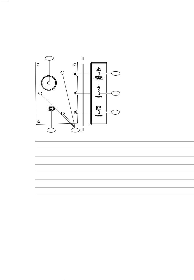
3.4 B46 overview (optional)
The B46 is an optional module that provides external B465 LED and sounder status when installed in a supported enclosure. The module has 3 LEDs (System Trouble, Power, and Battery) which illuminate through the B46 LED cover. The LED cover snaps into a knockout in the enclosure door. The B46 fits in the B10/B10R, D8103 enclosure. Refer to the following figure for component locations.
1
 BOSCH
BOSCH
2
3
4
6 |
5 |
Figure 3.3: B46 module overview
Callout Description
1 Sounder
2 SYSTEM TROUBLE LED
3 POWER LED
4 BATTERY LED
5 3-hole mounting pattern
6 B46/B465 cable connection
2015.09 | 03 | F.01U.311.207 |
Installation and Operation Guide |
Bosch Security Systems, Inc. |

Conettix Universal Dual Path |
System overview | en 15 |
|
Communicator |
||
|
||
|
|
2
1 |
BOSCH |
3
Figure 3.4: B46 LED cover (B10 enclosure shown)
Callout Description
1 B10 Medium Control Panel Enclosure, door closed
2 B46 LED cover
3 Enclosure lock (D101 supplied separately)
For LED patterns, refer to LED status indicators, page 75.
Bosch Security Systems, Inc. |
Installation and Operation Guide |
2015.09 | 03 | F.01U.311.207 |

16 en | Installation |
Conettix Universal Dual Path |
|
Communicator |
||
|
||
|
|
4 Installation
Perform the following steps to install the module.
Notice!
Notify the central station and any additional local authority before installing the B465 in an existing system.
Notice!
B46 External Annunciator installation
Refer to the B46 External Annunciator Installation Guide (P/N: F01U312441) prior to installing the enclosure for B465 module. There is a specific installation sequence you must follow to avoid damaging the B46 module during the installation process.
Caution!
!Remove all power (AC and battery) before making any connections. Failure to do so might result in personal injury and/or equipment damage.
4.1 |
Remove enclosure knockouts |
Review knockout locations before installing the enclosure on the wall. Each enclosure is slightly different regarding knockout locations and your desired use. Use a hammer and a punch-out tool to remove knockouts. Refer to the figures in this section for knockout locations.
Removing knockouts:
1.Review your wiring environment and decide on the appropriate knockouts to remove.
2.Lightly strike the wiring knockouts with a hammer and a punch-out tool.
3.Remove the metal knockout from the enclosure using pliers.
4.Lightly strike the 3-hole mounting knockouts with a hammer and a punch-out tool.
5.Remove the metal knockout from the enclosure using pliers.
6.Lightly strike the four corners of the enclosure door knockout when installing the B46 LED cover.
7.Remove the metal knockout from the enclosure using pliers.
Caution!
!Insert conduits into the enclosure knockout areas when running wire or cabling to reduce wire/cable damage.
2015.09 | 03 | F.01U.311.207 |
Installation and Operation Guide |
Bosch Security Systems, Inc. |
Conettix Universal Dual Path |
Installation | en 17 |
|
Communicator |
||
|
||
|
|
1 2
3

 1 1
1 1 

1 |
4 |
Figure 4.1: Suggested knockout locations
Callout Description
1 Suggested knockout locations for B465 wiring
2 Knockouts in enclosure door for B46 LED cover (optional for non-fire applications)
3 3-hole mounting knockouts for B46
4 Lockset mounting knockout
4.2 |
Mount the enclosure |
Mount one of the following enclosures in the desired location to meet desired UL requirements:
–B10 Medium Control Panel Enclosure (white)
–B10R Medium Control Panel Enclosure (red)
–B11 Small Control Panel Enclosure (white)
–B11R Small Control Panel Enclosure (red)
–D8103 Universal enclosure (this enclosure requires the B12 mounting plate)
–D8108A Attack Resistant Enclosure (this enclosure requires the B12 mounting plate) Installing the enclosure:
1.Remove any knockouts prior to installing the module.
2.Mount the enclosure in the desired location. Use all enclosure mounting holes. Refer to the mounting instructions supplied with the selected enclosure.
3.Pull any necessary wires/phone lines into the enclosure.
Bosch Security Systems, Inc. |
Installation and Operation Guide |
2015.09 | 03 | F.01U.311.207 |
18 en | Installation |
Conettix Universal Dual Path |
|
Communicator |
||
|
||
|
|
|
|
|
Notice!
Electromagnetic interference (EMI) can cause problems on long wire runs.
1 |
2 |
1 |
|
|
2 |
|
|
3 |
1 |
|
1 |
Figure 4.2: Enclosure mounting (B10 shown)
Callout Description
1 Enclosure mounting holes (4)
2 3-hole mounting locations (3)*
3 Tamper switch mounting locations
*Use the upper, right-hand 3-hole mounting location for installing the optional B46 module in the enclosure so it lines up with the enclosure door hole.
4.3 |
Insert wiring label |
Apply the supplied wiring label onto the inside of the enclosure door. Refer to the following figure.
2015.09 | 03 | F.01U.311.207 |
Installation and Operation Guide |
Bosch Security Systems, Inc. |
Conettix Universal Dual Path |
|
|
|
|
|
Installation | en |
19 |
Communicator |
|
|
|
|
|
||
|
|
|
|
|
|
|
|
|
Bosch Security Systems, Inc. recommends testing the entire system at least once a week, and having a qualified technician |
|
|||||
|
check the system at a minimum of once every 3 years. |
|
|
|
|
||
B465 |
This equipment has been type tested and found to comply with the specifications in Part 15 of FCC rules for Class B Computing |
|
|||||
Devices. Operation is subject to the two following conditions (1) this device may not cause any interference, and (2) this device |
|
||||||
must accept any interference received including interference that may cause undesired operation. |
|
|
|||||
|
|
|
|
|
Cellular plug-in modules |
|
|
|
|
|
|
|
B440/B441/B442/B443 |
|
|
|
|
|
|
|
|
LAN |
|
Do not connect |
|
|
|
|
|
Computer |
|
to a receptacle |
|
|
|
|
|
connection for |
|
controlled by a |
|
|
|
|
|
USB configuration |
|
switch. |
|
|
|
SYSTEM TROUBLE |
TRBL |
|
|
|
|
Supervised Inputs |
TX |
TX |
|
|
|
|
|
Open |
3.7 to 5.0 VDC |
RX |
RX |
|
|
|
|
Normal |
2.0 to 3.0 VDC |
POWER |
PWR |
|
|
|
|
Short |
0.0 to 1.3 VDC |
BATTERY |
BAT |
|
|
|
|
2.2 kΩ EOL Resistor |
|
|
B46 connection (optional) |
|
|
|
Future use |
(P/N: F01U034506) |
|
|
For connection to the optional |
|
|
|
SDI2 |
Required at End of Line. Inputs |
|
B46 module using the B46 |
|
||
|
Device Bus |
|
|
||||
|
R Y G B |
are to be used with dry contacts |
|
cable(P/N: F01U310747). |
|
||
|
|
and can handle up to 30 VDC. |
ICP-EZTS |
|
|||
|
|
Tamper |
|
|
|||
|
|
|
|
|
Switch |
|
|
+ - |
|
Earth |
Control Panel Phone Line Inputs |
2 |
|
Ground |
Simulated phone line on-hook: 28.3 VDC |
|
- |
|
off-hook: 2.0 to 8.0 VDC |
|
+ |
D126 - 7 Ah |
|
|
|
D1218 - 18 Ah |
|
|
12 VDC |
B465_ULLD-00c |
|||||
|
(Optional) 24 VDC |
(replace every |
|
|
up to 0.5A |
|
|
||||
|
3 to 5 years) |
|
|
|
|
Aux power |
This equipment should be installed in |
||||
|
from a UL listed fire |
|
|
|
Programmable |
|
|||||
|
control panel or |
|
|
|
output relays rated |
|
available |
accordance with the CSA C22.1, |
|||
|
power supply. |
|
|
|
|
|
Canadian Electrical Code, Part 1, Safety |
||||
|
|
|
|
|
30 VDC, 0.1A |
|
|
Standard for Electrical Installations. |
|||
Transformers: |
|
|
|
|
|
|
|
|
|
|
|
D1640 16.5 VAC |
Programmable Failsafe output, relay |
|
Auxilliary Powered Devices 11.5 to |
Communication: |
40 VA 60 HZ Class 2 plug-in |
energized during power-up, and then |
|
12.4 VDC. Below 10.2 VDC, the B465 |
Standard Line Security: Cellular or IP |
D1640-CA 120 VAC primary |
remains on while the B465 is |
|
A1: Cellular or IP |
|
16.5 VAC 40 VA secondary plug-in |
operating normally. Rated 30 VDC, |
|
stops processing Loop inputs. |
P1: DACT |
D1640-120WI 16.5 VAC |
0.5A |
|
|
|
40 VA 60 HZ Class 2 wire-in |
|
|
|
|
|
|
|
|
|
|
QUICK LED TROUBLESHOOTING |
|
|
|
|
|
|
|
|
|
|
|
|
|
|
|
|
|
|
|
|
|
|
|
|
|
|
|
|
|
|
|
|
||
|
|
|
|
SYSTEM TROUBLE LED |
SYSTEM TROUBLE Flashing (one flash) - Ethernet |
|
|
|
|
|
|
|
|
|
|
|
|
|
|
|
|
|
|
|
|
|
|
|
|
|
|
|
|
|
|
|||||
|
|
|
|
Flash pattern |
Function |
TX LED |
|
Function |
|
|
|
|
|
|
|
|
|
|
|
|
|
|
|
|
|
|
|
|
|
|
|
|
|
|
|
|
|
|
||
|
|
|
|
Off |
Indicates normal operations. |
Flashing (one flash) |
Ethernet Network Cable open. |
|
|
|
|
|
|
|
|
|
|
|
|
|
|
|
|
|
|
|
|
|
|
|
|
|
|
|
|
|
|
|||
|
|
|
|
Flashing (one flash) |
Indicates Ethernet communication errors (see |
Flashing (two flashes) |
Ethernet IP Address error. |
|
|
|
|
|
|
|
|
|
|
|
|
|
|
|
|
|
|
|
|
|
|
|
|
|
|
|
|
|
|
|||
|
|
|
|
|
|
SYSTEM TROUBLE Flashing one flash table). |
Flashing (three flashes) |
Ethernet DNS Lookup error. |
|
|
|
|
|
|
|
|
|
|
|
|
|
|
|
|
|
|
|
|
|
|
|
|
|
|
|
|
|
|
||
|
|
|
|
Flashing (two flashes) |
Indicates cellular communication errors (see |
|
|
|
|
|
|
|
|
|
|
|
|
|
|
|
|
|
|
|
|
|
|
|
|
|
|
|
|
|
|
|||||
|
|
|
|
SYSTEM TROULE Flashing (two flashes) - Cellular |
|
|
|
|
|
|
|
|
|
|
|
|
|
|
|
|
|
|
|
|
|
|
|
|
|
|
|
|
|
|
||||||
|
|
|
|
|
|
SYSTEM TROUBLE Flashing two flash table). |
|
|
|
|
|
|
|
|
|
|
|
|
|
|
|
|
|
|
|
|
|
|
|
|
|
|
|
|
|
|
||||
|
|
|
|
Flashing (three flashes) |
Indicates a communication trouble. |
Heartbeat |
RX |
|
Plug-in |
Function |
|
|
|
|
|
|
|
|
|
|
|
|
|
|
|
|
|
|
|
|
|
|
|
|
|
|
|
|||
|
|
|
|
Flashing (four flashes) |
Indicates multiple communication errors. |
LED |
LED |
|
Status LED |
|
|
|
|
|
|
|
|
|
|
|
|
|
|
|
|
|
|
|
|
|
|
|
|
|
|
|
|
|
|
|
|
|
|
|
On Steady |
Indicates low or missing battery, phone |
On Steady |
Flashing (one flash) |
N/A |
Plug-in module missing. |
|
|
|
|
|
|
|
|
|
|
|
|
|
|
|||||||||||||||||
|
|
|
|
|
|
lines are off the hook, or configuration issues. |
On Steady |
Flashing (two flashes) |
Off |
Plug-in module not recognized. |
|
|
|
|
|
|
|
|
|
|
|
|
|
|
||||||||||||||||
|
|
|
|
POWER LED |
|
On Steady |
Flashing (three flashes) |
Off |
Cellular modem failure. |
|
|
|
|
|
|
|
|
|
|
|
|
|
|
|
|
|
|
|
|
|
|
|
|
|
|
|
||||
|
|
|
|
Flash pattern |
Function |
1 Hz Flash |
Flashing (four flashes) |
On Steady |
Cellular DNS Lookup error. |
|
|
|
|
|
|
|
|
|
|
|
|
|
|
|
|
|
|
|
|
|
|
|
|
|
|
|
||||
1 |
|
|
|
On Steady |
Indicates a good AC level. |
1 Hz Flash |
Flashing (five flashes) |
On Steady |
Not activated. |
|
|
|
|
|
|
|
|
|
|
|
|
|
|
|
|
|
|
|
|
|
|
|
|
|
|
|
||||
|
|
|
Flashing (one flash) |
Indicates a AC low (brownout) or failure. |
1 Hz Flash |
Flashing (six flashes) |
On Steady |
Invalid access point. |
|
|
|
|
|
|
|
|
|
|
|
|
|
|
|
|
|
|
|
|
|
|
|
|
|
|
|
|||||
|
|
|
Off |
Is in an off state during the power up sequence. |
1 Hz Flash |
Off |
|
Flashing (one flash) |
No towers. |
|
|
|
|
|
|
|
|
|
|
|
|
|
|
|
|
|
|
|
|
|
|
|||||||||
|
|
BATTERY LED |
|
1 Hz Flash |
Off |
|
Flashing (two flashes) |
Cellular IP Address error. |
|
|
|
|
|
|
|
|
|
|
|
|
|
|
|
|
|
|
|
|
|
|
|
|
|
|
|
|||||
|
|
|
Flash pattern |
Function |
1 Hz Flash |
Off |
|
Flashing (three flashes) |
SIM Card missing. |
|
|
|
|
|
|
|
|
|
|
|
|
|
|
|
|
|
|
|
|
|
|
|||||||||
|
|
|
|
Off |
Indicates normal operations. |
1 Hz Flash |
Off |
|
Flashing (four flashes) |
SIM Card lockout. |
|
|
|
|
|
|
|
|
|
|
|
|
|
|
|
|
|
|
|
|
|
|
||||||||
|
|
|
|
Flashing (one flash) |
Indicates low battery voltage. |
1 Hz Flash |
Off |
|
Flashing (five flashes) |
Invalid SIM PIN. |
|
|
|
|
|
|
|
|
|
|
|
|
|
|
|
|
|
|
|
|
|
|
||||||||
|
|
|
|
For more information on LED troubleshooting, refer to the B465 Installation and |
|
|
|
|
|
|
|
|
|
|
|
|
|
|
|
|
|
|
|
|
|
|||||||||||||||
|
|
|
|
Flashing (two flashes) |
Indicates a missing battery (below 12.0 V) |
Operation Guide (P/N: F01U311207). |
|
|
|
|
|
|
|
|
|
|
|
|
|
|
|
|
|
|
|
|
|
|
|
|
|
|
|
|
|
|
||||
|
|
|
|
Flashing (three flashes) |
Indicates a bad battery (low for 72 hours). |
|
|
|
|
|
|
|
|
|
|
|
|
|
|
|
|
|
|
|
|
|
|
|
|
|
|
|
|
|
|
|||||
|
|
|
|
Flashing (four flashes) |
Indicates a battery charger failure. |
|
|
|
|
F01U312089-01 |
|
|
|
|
|
|
|
|
|
|
|
|
|
|
|
|
|
|
|
|
|
|||||||||
|
|
|
|
|
|
|
|
|
|
|
|
|
|
|
|
|
|
|
|
|
|
|
|
|
|
|
|
|
|
|
|
|
|
|
|
|
|
|
|
|
|
|
|
|
|
|
|
|
|
|
|
|
|
|
|
|
|
|
|
|
|
|
|
|
|
|
|
|
|
|
|
|
|
|
|
|
|
|
|
|
|
|
|
|
|
|
|
|
|
|
|
|
|
|
|
|
|
|
|
|
|
|
|
|
|
|
|
|
|
|
|
|
|
|
|
|
|
|
|
|
|
|
|
|
|
|
|
|
|
|
|
|
|
|
|
|
|
|
|
|
|
|
|
|
|
|
|
|
|
|
|
|
|
|
|
|
|
|
|
|
|
|
|
|
|
|
|
|
|
|
|
|
|
|
|
|
|
|
|
|
|
|
|
|
|
|
|
|
|
|
|
|
|
|
|
|
|
|
|
|
|
|
|
|
|
|
|
|
|
|
|
|
|
|
|
|
|
|
|
|
|
|
|
|
|
|
|
|
|
|
|
|
|
|
|
|
|
|
|
|
|
|
|
|
|
|
|
|
|
|
|
|
|
|
|
|
|
|
|
|
|
|
|
|
|
|
|
|
|
|
|
|
|
|
|
|
|
|
|
|
|
|
|
|
|
|
|
|
|
|
|
|
|
|
|
|
|
|
|
|
|
|
|
|
|
|
|
|
|
|
|
|
|
|
|
|
|
|
|
|
|
|
|
|
|
|
|
|
|
|
|
|
|
|
|
|
|
|
|
|
|
|
|
|
|
|
|
|
|
|
|
|
|
|
|
|
|
|
|
|
|
|
|
|
|
|
|
|
|
|
|
|
|
|
|
|
|
|
|
|
|
|
|
|
|
|
|
|
|
|
|
|
|
|
|
|
|
|
|
|
|
|
|
|
|
|
|
|
|
|
|
|
|
|
|
|
|
|
|
|
|
|
|
|
|
|
|
|
|
|
|
|
|
|
|
|
|
|
|
|
|
|
|
|
|
|
|
|
|
|
|
|
|
|
|
|
|
|
|
|
|
|
|
|
|
|
|
|
|
|
|
|
|
|
|
|
|
|
|
|
|
|
|
|
|
|
|
|
|
|
|
|
|
|
|
|
|
|
|
|
|
|
|
|
|
|
|
|
|
|
|
|
|
|
|
|
|
|
|
|
|
|
|
|
|
|
|
|
|
|
|
|
Figure 4.3: Applying the wiring label
Callout Description
1 Wiring label (supplied with the B465)
2 Enclosure door (inside view)
4.4 |
Insert D101 lock (optional) |
Refer to the instructions provided with the D101 for installation.
Notice!
The D101 lock is required for commercial fire installations.
4.5 |
Insert B46 LED cover (optional) |
The B46 has an LED cover so that the user can view the main B465 LED status indications from outside the supported enclosure. Perform the following to insert the LED cover. Installing the LED cover:
1.Locate the knockout area on the enclosure door. Refer to Remove enclosure knockouts, page 16.
Bosch Security Systems, Inc. |
Installation and Operation Guide |
2015.09 | 03 | F.01U.311.207 |

20 en | Installation |
Conettix Universal Dual Path |
|
Communicator |
||
|
||
|
3 |
|
1 |
2 |
|
|
4 |
Figure 4.4: Knock-out locations (B10/B10R/D8103 shown)
Callout Description
1 B10/B10R
2 Knockout location
3 D8103
4 Knockout location
2.Insert the plastic LED cover into the knockout area of the enclosure door. Refer to the following figure.
|
Figure 4.5: LED cover insertion |
|
|
3. |
Snap the cover into place. |
|
4. |
Verify that the cover is secure. |
|
Cover installation is complete! |
|
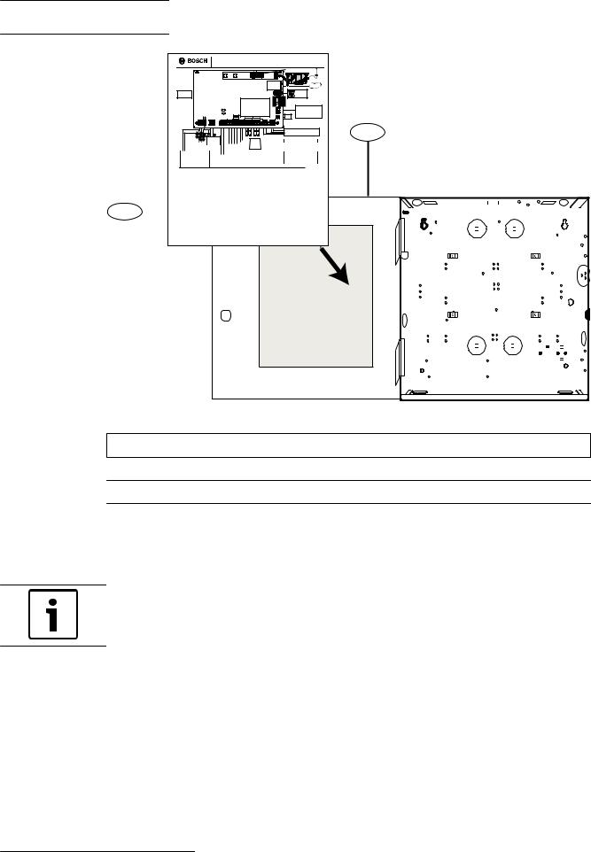
4.6 |
Install the module |
|
Perform the following to install the module.
Warning!
The module is static sensitive. Touch earth ground before handling the circuit board to
!discharge any static electricity from your body. Use a grounding strap while installing the circuit board.
4.6.1 |
Mount the module |
|
Identify the B465 mounting location in the enclosure before you begin mounting the module. |
|
|
2015.09 | 03 | F.01U.311.207 |
Installation and Operation Guide |
Bosch Security Systems, Inc. |
Conettix Universal Dual Path |
Installation | en 21 |
|
Communicator |
||
|
||
|
|
3 |
2 |
3 |
Figure 4.6: B10 and B11 mounting, wiring, and control panel placement locations
Callout Description
1 B10R Medium Control Panel Enclosure (Red)/B10 Medium Control Panel Enclosure
2 B11R Small Control Panel Enclosure (Red)/B11 Small Control Panel Enclosure
3 Mounting clip locations for the B465 Conettix Universal Dual Path Communicator
1.Snap the four supplied plastic standoffs onto four enclosure support posts.
Figure 4.7: Inserting plastic standoff onto enclosure posts
2.Place the module on top of the standoffs. Align the holes in the corners of the module with the openings at the top of each standoff. Secure the module to the standoffs with supplied, self-threading screws.
Bosch Security Systems, Inc. |
Installation and Operation Guide |
2015.09 | 03 | F.01U.311.207 |

22 en | Installation |
Conettix Universal Dual Path |
|
Communicator |
||
|
||
|
|
|
|
|
|
|
|
|
|
|
|
|
|
|
|
|
|
|
|
|
|
|
|
|
|
|
|
|
|
|
|
|
|
|
|
|
|
|
|
|
|
|
|
|
|
|
|
|
|
|
|
|
|
|
|
|
|
|
|
|
|
|
|
|
|
|
|
|
|
|
|
|
|
|
|
|
|
|
|
|
|
|
|
|
|
|
|
|
|
|
|
|
|
|
|
|
|
|
|
|
|
|
|
|
|
|
|
|
|
|
|
|
|
|
|
|
|
|
|
|
|
|
|
|
|
|
|
|
|
|
|
|
|
|
|
|
|
|
|
|
|
|
|
|
|
|
|
|
|
|
|
|
|
|
|
|
|
|
|
|
|
|
|
|
Figure 4.8: Mounting B465 on standoffs |
|||||||
|
D8103 installation |
|||||||
|
Refer to the B12 Mounting Plate Installation Instructions (P/N: F01U262949) for installing the |
|||||||
|
required B12 mounting plate if in the D8103 Universal enclosure, or D8108A Attack Resistant |
|||||||
|
Enclosures. Use the included hardware to install the B465 to the B12 Mounting Plate. |
|||||||
4.6.2 |
Mount the B46 (optional) |
|||||||
|
The B46 is an optional module which provides LED status from the B465. The B46 cover |
|||||||
|
mounts externally to the enclosure door and is installed internally inside the enclosure. |
|||||||
|
|
|
|
|
|
|
|
|
Notice!
The B46 is required when the FACP is not able to indicate B465 troubles locally
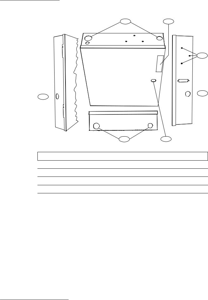
Mount the module into the enclosure’s 3-hole mounting pattern using the supplied mounting screws and mounting bracket. Refer to the figure below.
2015.09 | 03 | F.01U.311.207 |
Installation and Operation Guide |
Bosch Security Systems, Inc. |

Conettix Universal Dual Path |
|
Installation | en 23 |
Communicator |
|
|
|
|
|
|
|
|
|
|
|
Figure 4.9: B46 mounting into B10 enclosure
Callout Description
1 Module with mounting bracket installed
2 Enclosure
3 Mounting screws (3)
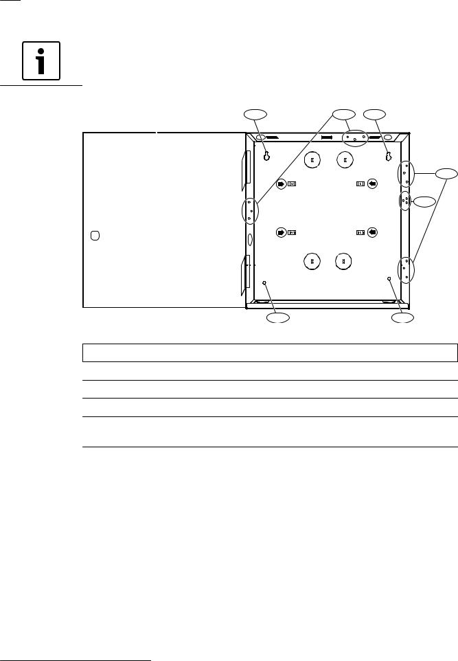
Refer to the figure below for B46 enclosure mounting locations.
Notice!
Install the B46 in the upper, right-hand corner of the enclosure as shown in the following figure.
Bosch Security Systems, Inc. |
Installation and Operation Guide |
2015.09 | 03 | F.01U.311.207 |

24 en | Installation |
Conettix Universal Dual Path |
|
Communicator |
||
|
||
|
|
2
Y |
1
24 VDC |
|
OR |
|
16.5 VAC |
BATTERY |
3
MODULE 1 |
|
X |
|
|
MODULE |
|
RELEASE |
COMMUNICATION MODULE 1 |
|
|
ETHERNET |
100BASE-T |
ETHERNET |
LINK
USB |
|
|
SYSTEM TROUBLE |
TRBL |
|
|
|
|
TX |
TX |
SDI2 |
|
|
RX |
RX |
|
|
POWER |
|
|
DEVICE BUS |
|
|
PWR |
|
R Y G B |
|
|
BATTERY |
BAT |
INPUTS |
PANEL |
PANEL |
EXTERNAL ANNUNC |
|
2.2 K |
END OF |
|||
LINE RESISTORS |
|
|
|
|
1 COM 2 |
3 COM 4 |
LINE 1 |
LINE 2 |
TMPR |
|
|
|
|
|
|
16.5VAC |
|
|
+ - |
|
NC C NO |
C NO |
C NO |
12V |
1 COM 2 3 COM 4 |
|
T R |
|
T R |
|
||
|
|
|
|
BATTERY |
|
RELAY 1 |
RELAY 2 |
RELAY 3 |
AUX COM |
|
PNL LINE 1 |
PNL LINE 2 |
|
||||
|
|
|
|
|
|
|
|
|
|
|
|
|
|
|
|
|
|
Figure 4.10: Mounting the B46 into an enclosure
Callout Description
1 Enclosure (B10/B10R shown)
2 B465 module
3 B46 module
4.6.3 Connect earth ground
To help prevent damage from electrostatic discharges or other transient electrical surges, connect the system to earth ground before making other connections. The  icon indicates the earth ground terminal. Use a recommended earth ground reference, such as a grounding rod or a metal cold water pipe. Make the connection using 14 AWG (1.8 mm) to 16 AWG (1.5 mm) wire.
Notice!
Do not use telephone or electrical ground for the earth ground connection. Do not connect other control panel terminals to earth ground.
Caution!
!Avoid electrostatic discharge. Always touch the earth ground connection with the  icon first, before beginning work on the control panel.
2015.09 | 03 | F.01U.311.207 |
Installation and Operation Guide |
Bosch Security Systems, Inc. |

Conettix Universal Dual Path |
Installation | en 25 |
|
Communicator |
||
|
||
|
|
|
|
|
Notice!
In ground fault enabled systems, you might cause a ground fault when connecting a computer to the B465 for programming.
4.7 |
Insert the cellular communication module (optional) |
Insert the desired B44x communication module into the slot of the module until you feel the module “click” into place.
For cellular communication, use one of the following:
–B440 Conettix Plug-in Cellular Communicator (3G Verizon – US only)
–B441 Conettix Plug-in Cellular Communicator (Verizon – US only)
–B442 Conettix Plug-in GPRS Cellular Communicator (outside the USA where approved)
–B443 Conettix Plug-in HSPA+ Cellular Communicator (where approved)
Install the cellular module
1.Power down the B465.
2.Insert the communication module into the stabilizing plug-in holes and plug-in module connector as shown in callouts #2 and 3 in Module overview, page 9.
3.Connect the antenna to the module by screwing onto the threaded conector.
4.Route the antenna cable through a wire knockout in the top of the enclosure.
5.Secure the antenna cable to the outside of the enclosure.
Notice!
If you experience a weak signal, place the antenna on top of a metal surface that has a radius of 10.16 cm (4 in) or larger for optimal performance.
|
|
|
|
|
|
|
|
|
|
|
|
MODULE 1 |
|
|
|
|
|
|
|
|
|
|
Y |
|
|
|
X |
|
|
|
|
|
|
|
|
|
|
|
|
|
|
|
|
|
|
|
|
|
|
|
|
|
|
|
|
MODULE |
|
|
|
|
|
|
|
|
|
|
|
|
|
|
|
|
|
|
RELEASE |
|
|
|
|
|
|
|
|
COMMUNICATION MODULE 1 |
|
|
|
|
|
|
||||
|
|
|
|
|
|
|
|
|
|
|
|
|
|
|
|
|
ETHERNET |
|
|
|
|
|
|
|
|
|
|
|
|
|
|
100BASE-T |
|
|
ETHERNET |
||
|
|
|
|
|
|
|
|
|
|
|
|
|
|
LINK |
|
|
|
|
|
|
|
|
|
|
|
|
|
|
|
|
|
|
|
|
USB |
|
|
|
|
|
|
|
|
|
|
|
|
|
|
|
|
SYSTEM TROUBLE |
TRBL |
|||
|
|
|
|
|
|
|
|
|
|
|
|
|
|
|
|
|
TX |
TX |
|
|
|
|
|
|
|
|
SDI2 |
|
|
|
|
|
|
|
|
RX |
RX |
|
|
|
|
|
|
|
DEVICE BUS |
|
|
|
|
|
|
POWER |
PWR |
|||
|
|
|
|
|
|
|
R |
Y G |
B |
|
|
|
|
|
|
BATTERY |
BAT |
|
OR |
|
|
|
|
|
|
|
|
|
|
INPUTS |
|
PANEL |
PANEL |
EXTERNAL ANNUNC |
|||
|
|
|
|
|
|
|
|
|
|
2.2 K |
END OF |
|
||||||
24 VDC |
|
|
|
|
|
|
|
|
|
|
LINE RESISTORS |
|
|
|
|
|
|
|
16.5 VAC |
BATTERY |
|
|
|
|
|
|
|
1 COM 2 |
3 COM 4 |
LINE 1 |
LINE 2 |
TMPR |
|||||
|
|
|
|
|
|
|
|
|
|
|
|
|
|
|
|
|
|
|
16.5VAC |
+ |
- |
NC C |
NO |
C |
NO |
C |
NO |
12V |
1 |
COM 2 |
3 COM |
4 |
T |
R |
T |
R |
|
|
BATTERY |
RELAY 1 |
RELAY 2 RELAY 3 AUX COM |
|
|
|
|
PNL LINE 1 |
PNL LINE 2 |
|
||||||||
Figure 4.11: Cellular plug-in module insertion
4.8 |
Wiring installation |
Refer to the following sections for detailed wiring information.
4.8.1 |
System wiring |
You can use the B465 with a variety of intrusion and fire control panels that support the B465’s compatible protocols.
Bosch Security Systems, Inc. |
Installation and Operation Guide |
2015.09 | 03 | F.01U.311.207 |

26 en | Installation |
Conettix Universal Dual Path |
|
Communicator |
||
|
||
|
|
MODULE 1
Y X
MODULE
RELEASE
COMMUNICATION MODULE 1 |
|
|
|
|
|
|
|
|
ETHERNET |
||
100BASE |
-T |
|
|
ETHERNET |
|
|
|
|
|
|
|
LINK
USB |
|
|
|
|
|
|
|
|
|
|
|
|
|
|
|
|
|
|
|
|
|
|
SYSTEM TROUBLE |
||||
|
|
|
|
|
|
|
|
|
|
|
|
|
|
|
|
|
|
|
|
|
|
|
|
TX |
||
|
|
|
|
|
|
|
|
|
|
|
|
SDI2 |
|
|
|
|
|
|
|
|
|
RX |
||||
|
|
|
|
|
|
|
|
|
|
|
|
|
|
|
|
|
|
|
|
POWER |
||||||
|
|
|
|
|
|
|
|
|
|
|
DEVICE BUS |
|
|
|
|
|
|
|
|
|||||||
|
|
|
|
|
|
|
|
|
|
|
|
|
|
|
|
|
|
|
|
|
|
|
||||
|
|
|
|
|
|
|
|
|
|
R Y G B |
|
|
|
|
|
|
|
|
BATTERY |
|||||||
|
|
|
|
|
|
|
|
|
|
|
|
|
|
|
|
|
|
INPUTS |
|
|
|
|
|
|
||
|
|
|
|
|
|
|
|
|
|
|
|
|
|
|
|
|
2.2 K |
END OF |
|
|
|
|
|
|
||
24 VDC |
|
|
|
|
|
|
|
|
|
|
|
|
|
|
|
LINE RESISTORS |
|
|
|
|
|
|
||||
|
OR |
|
|
|
|
|
|
|
|
|
|
|
|
|
|
|
|
|
|
|
|
PANEL |
|
PANEL |
||
16.5 VAC |
|
|
|
|
|
|
|
|
|
|
|
|
|
|
1 COM 2 |
|
3 COM 4 |
|
|
|||||||
BATTERY |
|
|
|
|
|
|
|
|
|
|
LINE 1 |
|
LINE 2 |
|
|
|||||||||||
|
|
|
|
|
|
|
|
|
|
|||||||||||||||||
|
|
|
|
|
|
|
|
|
|
|
|
|
|
|
|
|
|
|
|
|
|
|
|
|
|
|
|
|
|
|
|
|
|
|
|
|
|
|
|
|
|
|
|
|
|
|
|
|
|
|
|
|
|
|
|
|
|
|
|
|
|
|
|
|
|
|
|
|
|
|
|
|
|
|
|
|
|
|
|
|
|
|
|
|
|
|
|
|
|
|
|
|
|
|
|
|
|
|
|
|
|
|
|
|
|
|
|
|
|
|
|
|
|
|
|
|
|
|
|
|
|
|
|
|
|
|
|
|
|
|
|
|
|
|
|
|
|
|
|
|
|
|
|
|
|
|
|
|
|
|
|
|
|
|
|
|
|
|
|
|
|

 TRBL
TRBL 
 TX
TX 
 RX
RX 
 PWR
PWR 
 BAT
BAT
EXTERNALANNUNC
TMPR
16.5VAC |
|
|
|
|
+ - |
NC C NO |
C NO |
C NO |
12V |
1 COM 2 |
3 COM 4 |
T R |
T R |
|
|
|
|
|
|
BATTERY |
RELAY 1 |
RELAY 2 |
RELAY 3 |
AUX COM |
|
|
PNL LINE 1 |
PNL LINE 2 |
|
|
|
|
|
|
|
|
|
|
|
|
|
|
|
|
+
 _
_
1
2
3
|
10 |
9 |
8 |
7 |
6 |
|
5 |
4 |
Figure 4.12: System wiring |
|
|
|
|
|
|||
|
|
|
|
|||||
Callout Description |
|
|
Callout Description |
|||||
|
|
|
|
|
||||
1 |
RJ-45 modular jack for Ethernet IP |
|
6 |
12V AUX/COM terminals (optional output |
||||
communications (optional) |
|
|
power source, Special Application 9.9 – 13.8 |
|||||
|
|
|
|
|
|
V) |
|
|
|
|
|
|
|
||||
2 |
Connector for External Annunciator |
|
7 |
Programmable output relays (Relay 1, |
||||
(connected to optional B46) |
|
|
Relay 2, Relay 3) |
|
||||
|
|
|
|
|
|
|||
3 |
To tamper switch |
|
|
8 |
12 VDC lead-acid battery (7-18 Ah) |
|||
|
|
|
|
|
||||
4 |
Phone Line 1/2 (to control panel |
|
9 |
To earth ground |
||||
terminals if required) |
|
|
|
|
|
|||
|
|
|
|
|
||||
5 |
Four EOL input loops |
|
|
10 D1640 plug-in transformer, D1640-CA |
||||
|
|
|
|
|
|
plug-in transformer, D1640-120WI wired-in |
||
|
|
|
|
|
|
transformer or optional 24 VDC from a UL |
||
|
|
|
|
|
|
listed fire control panel or power supply. |
||
|
|
|
|
|
|
|
|
|
Notice!
For Ground Fault detection, a wire must be run between AUX – (internal common ground, not earth ground) of both the FACP and the B465.
2015.09 | 03 | F.01U.311.207 |
Installation and Operation Guide |
Bosch Security Systems, Inc. |
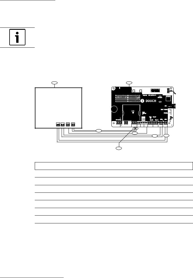
Conettix Universal Dual Path |
Installation | en 27 |
|
Communicator |
||
|
||
|
|
Wiring to a SDI2 device
The SDI2 Device Bus terminal connector is designed for future use.
Notice!
The SDI2 Device Bus terminal connector has not been tested by UL.
4.8.2 |
Control panel to dialer capture wiring |
|
|
Use the correct wire gauge when connecting a B465 to an intrusion/fire control panel |
|
|
terminals (14-24AWG). Refer to the following figure for wiring information. |
|
|
1 |
2 |
MODULE 1
Y X
COMMUNICATION MODULE 1
100BASE-T
LINK
MODULE
RELEASE
ETHERNET
ETHERNET
USB |
24 VDC OR
16.5 VAC |
BATTERY |
|
|
|
|
|
|
|
|
|
SYSTEM TROUBLE |
|
|
|
|
|
|
|
|
|
|
|
TX |
|
|
|
|
SDI2 |
|
|
RX |
|||
|
|
|
|
|
|
POWER |
||||
|
|
|
DEVICE BUS |
|
|
|||||
|
|
|
R Y G B |
|
|
BATTERY |
||||
|
|
|
|
|
|
|
INPUTS |
|
|
|
|
|
|
|
|
|
|
2.2 K |
END OF |
|
|
|
|
|
|
|
|
|
LINE RESISTORS |
PANEL |
PANEL |
|
|
|
|
|
|
|
|
1 COM 2 |
3 COM 4 |
LINE 1 |
LINE 2 |
|
|
|
|
|
|
|
|
|
|
|
|
|
|
|
|
|
|
|
|
|
|

 TRBL
TRBL 
 TX
TX 
 RX
RX 
 PWR
PWR 
 BAT
BAT


 TMPR
TMPR  EXTERNALANNUNC
16.5VAC |
+ - |
NC C NO |
C NO |
C NO 12V 1 COM 2 3 COM 4 |
T R |
T R |
|
BATTERY |
RELAY 1 |
RELAY 2 |
RELAY 3 AUX COM |
PNL LINE 1 |
PNL LINE 2 |
PSTN |
PSTN |
AUX/COM |
ZONE INPUT |
|
2 |
1 |
|
|
|
|
|
|
7 |
|
|
|
|
5 |
|
|
|
|
4 |
3 |
6
Figure 4.13: Panel to dialer capture wiring
Callout Description
1 Fire/intrusion control panel
2 B465
3 Optional second panel phone connection depending on equipment
4 Primary phone connection
5 Internal Ground (AUX Power negative or internal Common) required for Commercial Fire
6 Control panel EOL resistor (required for supervision with callout #7)
7 Optional for local B465 troubles
4.8.3 |
Control panel to dry contact wiring |
Use the correct wire gauge when connecting a B465 to an intrusion/fire control panel terminals (14-24AWG). Refer to the following figure for wiring information.
Bosch Security Systems, Inc. |
Installation and Operation Guide |
2015.09 | 03 | F.01U.311.207 |

28 en | Installation |
Conettix Universal Dual Path |
|
Communicator |
||
|
||
|
|
|
1 |
2 |
Y |
24 VDC OR
16.5 VAC |
BATTERY |
MODULE 1 |
|
X |
|
|
MODULE |
|
RELEASE |
COMMUNICATION MODULE 1 |
|
|
ETHERNET |
100BASE-T |
ETHERNET |
LINK
USB |
|
SYSTEM TROUBLE |
TRBL |
|
|
|
TX |
TX |
SDI2 |
|
RX |
RX |
|
POWER |
|
|
DEVICE BUS |
|
PWR |
|
R Y G B |
|
BATTERY |
BAT |
|
PANEL |
PANEL |
EXTERNAL ANNUNC |
INPUTS |
|
|
|
2.2 K |
END OF |
|
|
LINE RESISTORS |
|
|
|
1 COM 2 |
3 COM 4 LINE 1 |
LINE 2 |
TMPR |
|
|
|
|
16.5VAC |
+ - |
NC C NO |
C NO |
C NO 12V 1 COM 2 3 COM 4 |
T R |
T R |
|
BATTERY |
RELAY 1 |
RELAY 2 |
RELAY 3 AUX COM |
PNL LINE 1 |
PNL LINE 2 |
FIRE |
FIRE |
AUX/ |
ZONE INPUT |
ALARM |
SUPERVISORY |
TROUBLE COM |
|
8
9
7
5
4
3
6
Figure 4.14: Panel to dry contact wiring
Callout Description
1 Fire/intrusion control panel
2 B465
3 Fire alarm connection
4 Fire supervisory connection
5 Trouble (AC Fail, Low Battery, etc)
6 Control panel EOL resistor (required for supervision with callout #8)
7 Internal Ground (AUX power negative or internal Common) required for Commercial Fire
8 Optional panel inputs for B465 troubles
9 B465 EOL resistors
4.8.4 B46 module wiring (optional)
Use the cable supplied with the B46 to connect to the B465 module. Refer to System overview, page 9 section for component location. Refer to the figure below.
2015.09 | 03 | F.01U.311.207 |
Installation and Operation Guide |
Bosch Security Systems, Inc. |

Conettix Universal Dual Path |
Installation | en 29 |
|
Communicator |
||
|
||
|
|
1
2
MODULE 1
Y X
MODULE
RELEASE
COMMUNICATION MODULE 1 |
|
|
|
|
|
|
|
|
ETHERNET |
||
100BASE |
-T |
|
|
ETHERNET |
|
|
|
|
|
|
|
LINK
USB |
|
|
|
|
|
|
SYSTEM TROUBLE |
TRBL |
|
|
|
|
|
|
|
|
||
|
|
|
|
|
|
|
TX |
TX |
|
|
SDI2 |
|
|
|
|
RX |
RX |
|
|
|
|
|
|
POWER |
|
|
|
DEVICE BUS |
|
|
|
PWR |
|||
|
|
|
|
|
|
|||
|
R |
Y G |
B |
|
|
|
BATTERY |
BAT |
|
|
|
|
INPUTS |
PANEL |
PANEL |
EXTERNAL ANNUNC |
|
|
|
|
|
2.2 K |
END OF |
|
|
|
24 VDC |
|
|
|
LINE RESISTORS |
|
|
|
|
OR |
|
|
|
|
|
|
|
|
16.5 VAC |
BATTERY |
|
|
1 COM 2 |
3 COM 4 |
LINE 1 |
LINE 2 |
TMPR |
|
|
|
|
|
||||
|
|
|
|
|
|
|
|
|
|
|
|
|
|
+ |
- |
|
|
|
|
|
|
|
|
|
|
|
16.5VAC |
|
|
|
NC C NO |
C NO |
C NO |
12V |
1 COM 2 |
3 COM 4 |
T R |
|
T R |
|
||
|
|
|
|
|
BATTERY |
RELAY 1 |
RELAY 2 |
RELAY 3 |
AUX COM |
|
|
PNL LINE 1 |
PNL LINE 2 |
|
||
|
|
|
|
|
|
|
|
|
|
|||||||
|
|
|
|
|
|
|
|
|
|
|
|
|
|
|
|
|
3
Figure 4.15: B46 cable connection
Callout Description
1 B465 module
2 B46
3 B46 Cable (P/N: F01U310747) included with the B46
|
Notice! |
|
The white wires of the B46 cable should be facing the words “EXTERNAL ANNUNCIATOR.” |
|
|
|
|
|
Notice! |
|
Ensure the placement of the B46 cable does not obstruct the LEDs of the B465 when |
|
inserting into the port of the B465. |
|
|
4.8.5 |
Input loop wiring |
|
The B465 provides four on-board inputs. Each input functions independently and does not |
|
interfere with the operation of the others. The module monitors the input loops for normal, |
|
shorted, or open conditions between an input terminal and any of the input common |
|
terminals. |
|
The programming for the input determines how the module responds to these conditions. |
|
The module ignores input loops for 120 seconds after power up to ensure that the |
|
connections have stabilized. |
Input loops
Install a 2.21 kΩ resistor at the far end of the input loop when wiring the on-board inputs to provide a reference for supervision. The total resistance for the wire length and contacts, minus the end-of-line (EOL) resistor, must not exceed 100 Ω.
Bosch Security Systems, Inc. |
Installation and Operation Guide |
2015.09 | 03 | F.01U.311.207 |

30 en | Installation |
Conettix Universal Dual Path |
|
Communicator |
||
|
||
|
|
1
2
3
4
7
2.21 kΩ
2
3 

 5
5
8 |
9 |
2
3
6
Figure 4.16: On-board input loop wiring
Callout Description
1 100 Ω maximum (total wire out and back)
2 Input terminal
3 Common
4 Normally closed contacts (NC)
5 Normally open contacts (NO)
6 Combination: Normally open contacts and normally closed contacts (NO/NC)
7 2.21 kΩ EOL resistor (P/N: F01U034506)
8 Red
9 Brown
Notice!
You do not need to install the End of Line (EOL) resistor for unused inputs (inputs are disabled by default).
UL does not permit normally closed loops for commercial fire applications.
Input voltage parameters
You can determine the condition of on-board inputs 1 to 4 by measuring the voltage across the input terminal (1 to 4) and the point COM terminal. The loop wiring must be connected and the 2.21 kΩ EOL resistor must be in place and the input function programmed.
1 |
COM |
2 |
3 |
COM |
4 |
Figure 4.17: Input terminals
2015.09 | 03 | F.01U.311.207 |
Installation and Operation Guide |
Bosch Security Systems, Inc. |
Loading...