


B810
Table of contents
 Loading...
RADION receiver SD
B810
en Reference Guide

Table of contents
1
Introduction 5
1.1 About documentation 5
1.2 Bosch Security Systems, Inc. product manufacturing dates 5
2
General installation 6
2.1 Installation workflow 6
2.2 Unpacking information 7
2.3 Wall tamper switch installation 7
2.4 Magnet cover installation 7
2.5 Complete installation 7
2.6 Maintenance 8
3
RADION receiver SD 9
3.1 Certifications and approvals 9
3.2 UL product requirements 10
3.3 B810 installation 13
3.3.1 B810 configuration 13
3.3.2 Base mounting installation 14
3.3.3 Wiring considerations 15
3.3.4 Programming wireless points in the control panel 15
3.3.5 Enroll point RF ID for wireless points (Auto-learn mode) 17
3.3.6 Walk test (for motion detectors) 18
3.3.7 Signal level and margin 18
3.3.8 Complete the installation 19
3.3.9 B810 system test 19
3.4 External LED states 20
3.4.1 LEDs 21
3.5 Specifications (B810) 22
3.5.1 Battery requirements 22
4
RADION repeater 24
4.1 Installation considerations 24
4.2 Wiring considerations 24
4.3 Specifications 25
4.4 LEDs 25
5
RADION glassbreak 27
5.1 Installation considerations 27
5.2 Testing 28
5.3 Low battery 29
5.4 Wall Tamper Tab 30
5.5 Maintenance 30
6
RADION TriTech 31
6.1 Mounting height and range adjustment 31
6.2 Sensitivity settings 32
6.3 Walk testing 32
7
RADION PIR 34
7.1 Walk testing 34
8
RADION PIR C 36
8.1 Walk testing 36
RADION receiver SD Table of Contents | en 3
Bosch Security Systems, Inc. Reference Guide 2015.10 | 08 | F.01U.261.834
9
RADION smoke 38
9.1 Battery replacement 39
9.2 Smoke test 39
9.3 Sensitivity test 39
9.4 Test/Silence button 40
9.5 LED 40
9.6 Clean the detector and replace the optical chamber 40
10
RADION contact SM 42
10.1 Installation considerations 42
11
RADION contact RM 44
11.1 Installation considerations 44
12
RADION specialty 46
12.1 Applications for this product 47
12.2 Installation consideration 47
13
RADION universal transmitter 48
13.1 Installation considerations 49
13.2 Reed switch settings 50
14
RADION keyfob 51
14.1 RADION keyfob FB 52
14.2 RADION keyfob TB 52
15
RADION panic 54
16
Appendices 56
4 en | Table of Contents RADION receiver SD
2015.10 | 08 | F.01U.261.834 Reference Guide Bosch Security Systems, Inc.
Introduction
This document contains the basic information that a trained installer needs to install the
RADION system. It supplements the documents listed inside the packaging (graphical
installation guides).
This reference guide contains:
– A description of the general installation procedure.
– Device-specific installation procedures.
– Specification information.
How to use this document
The information contained in this document is constructed in a manner that is systematic and
sequential for the installer on a “point of need” basis. The following represents a basic outline
of that information;
– Chapter 1 (this chapter) – introductory information and how to use this document.
– Chapter 2 – basic RADION system-wide general installation information and workflow
check list.
– Chapter 3 – RADION receiver-specific installation information.
– Remaining chapters – RADION device-specific installation information.
– Appendix – description of various icons and symbols used within the RADION
documentation.
Icons and symbols
When you see the following logo in the RADION graphical installation guides listed in Table
3.1, refer to the appropriate section in this document.
Additional icons and symbols, which appear in the RADION graphical installation guides, are
explained in the appendix section of this guide. Refer to the Appendices, page 56 for more
information.
About documentation
Copyright
This document is the intellectual property of Bosch Security Systems, Inc. and is protected by
copyright. All rights reserved.
Trademarks
All hardware and software product names used in this document are likely to be registered
trademarks and must be treated accordingly.
Bosch Security Systems, Inc. product manufacturing dates
Use the serial number located on the product label and refer to the Bosch Security Systems,
Inc. website at http://www.boschsecurity.com/datecodes/.
1
1.1
1.2
RADION receiver SD Introduction | en 5
Bosch Security Systems, Inc. Reference Guide 2015.10 | 08 | F.01U.261.834
General installation
Phases of installation
The installation of the RADION system is achieved by following the sequential process as
defined in this chapter. Overall, there are four main phases;
– Planning
– Physical installation of the devices
– System enrollment/configuration
– System testing (walk test, pattern test)
It is essential that these steps or phases are adhered to in the order mentioned above for
proper functionality and operation.
When installing a RADION system, you must plan your installation based on the control panel
and RADION device specifications, and the radio-frequency signal strength (RFSS) between
devices, receivers, and control panels.
Installation considerations
– RADION devices are intended only for indoor, dry applications.
– Mount RADION devices on flat, rigid surfaces. Some devices can be optionally corner
mounted as indicated in the installation instructions.
– Avoid mounting RADION devices in areas with large, metallic objects, electrical panels, or
electric motors. They might reduce the radio-frequency (RF) range of a RADION device.
– Avoid installing the devices where excessive humidity, moisture, or temperatures outside
of the acceptable operating range exist.
– Wire all objects according to their specifications.
– RADION devices use batteries of varying types. When installing batteries, observe safety
and polarity recommendations as indicated in the documentation for those products.
Installation workflow
To install, configure, and test the system, use the workflow below and follow in sequential
order, from top to bottom, checking each box as you complete a step.
Notice!
Always power down the control panel when connecting modules, or other wiring. Power
down the control panel by unplugging the transformer and disconnecting the battery
Plan the installation of the RADION system
Install the RADION components (refer to the graphical installation guides and this system
reference guide for details)
Program wireless points in the control panel
Enroll point RF ID for wireless points
Verify LED responses on devices
Perform a local walk test for installed detectors
Review signal strength and margin of each point
Complete the installation
2
2.1
6 en | General installation RADION receiver SD
2015.10 | 08 | F.01U.261.834 Reference Guide Bosch Security Systems, Inc.
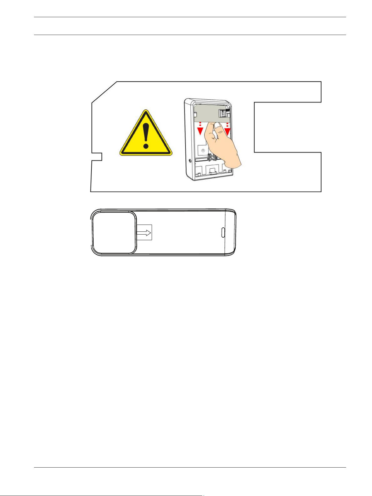
Unpacking information
When unpacking the receiver, repeater, or bill trap device, it is important to remove the
cardboard insert as illustrated below;
Figure 2.1: Insert for the receiver and repeater
Figure 2.2: Insert for the bill trap
Wall tamper switch installation
RADION transmitter devices contain a feature that activates the wall tamper switch located on
the base of the device. In order to properly install the device, you must consider the following:
– To properly install a device with active wall tamper functionality, insert a screw in the
designated screw slot location.
– Failure to insert a screw into the wall tamper slot prevents the wall tamper feature from
generating a tamper signal when the transmitter is pulled away from a wall.
Magnet cover installation
During the installation of the plastic magnet cover, the cover is not designed to be separated
from the base after the base and cover are snapped together. Damage to the plastics may
occur if separated.
Complete installation
Testing the entire RADION system can only be achieved by performing an area wide test
through the control panel and corresponding keypad(s). This is achieved by performing an
overall service walk test. Refer to your control panel documentation for system-walk, or other
system-wide testing procedures.
2.2
2.3
2.4
2.5
RADION receiver SD General installation | en 7
Bosch Security Systems, Inc. Reference Guide 2015.10 | 08 | F.01U.261.834
To ensure proper operation of the RADION devices, test the basic functionality of the device
locally. Depending on the RADION device to be tested, perform the following procedures for
functionality:
– When testing the receiver, power up the compatible control panel in which the receiver is
connected to and observe the LED behavior on the receiver.
– Local walk testing can be performed on the motion detectors as defined in the tritech
and PIR chapters of this guide.
– Magnet testing can be performed by opening or closing the door/window in which the
magnet is installed on.
Maintenance
It is recommended to check the battery of each device annually. This will ensure proper
operation and functionality of the devices.
Battery Life Extension feature (PIR and TriTech)
In the normal operating mode, an alarm can be transmitted only after three (3) minutes have
passed since the previous alarm restoral. This 3 minute lockout time reduces unnecessary RF
transmissions in high traffic areas, thereby extending battery life.
2.6
8 en | General installation RADION receiver SD
2015.10 | 08 | F.01U.261.834 Reference Guide Bosch Security Systems, Inc.

RADION receiver SD
The B810 is a wireless receiver that connects RADION wireless peripherals to supported
Bosch control panels via the SDI2 bus connection. A compatible control panel powers the
receiver through the wiring connection. Features include:
– Easy addressing via a rotary switch
– Cover and wall tamper protection
– RFID and configuration data are contained in persistent memory
– External LED
– Detection and reporting radio frequency interference
– Supports supervision of wireless points (504), keyfobs (1000), and repeaters (8)
Use this reference guide along with the control panel’s documentation and each device’s
installation instructions to complete the installation process.
Certifications and approvals
Listings and approvals
UL
The B810 is UL listed for Commercial/Residential Burglar Alarm Systems, and Household Fire
Warning System Units.
Products evaluated by UL
The following products have been evaluated by UL:
– B810 wireless receiver
– RFRP-A repeater
– RFBT-A specialty (billtrap)
– RFDW-SM-A standard door/window contact
– RFDW-RM-A recessed door/window contact
– RFDL-11-A motion detector
– RFPR-12-A PIR motion detector
– RFPR-C12-A PIR motion detector (curtain)
– RFUN-A universal transmitter
– RFSM-A smoke detector
– RFKF-TB-A keyfob
– RFKF-FB-A keyfob
– RFPB—TB-A panic
– RFPB-SB-A panic
– RFKF-FBS-A keyfob
– RFKF-TBS-A keyfob
Products not evaluated by UL
The following products have not been evaluated by UL:
– RFGB-A glassbreak
UL battery requirements
UL recommends to check the battery of each device annually. This will ensure proper
operation and functionality of the devices.
For the RFBT-A bill trap, UL requires the battery to be replaced annually to ensure optimal
performance.
3
3.1
RADION receiver SD RADION receiver SD | en 9
Bosch Security Systems, Inc. Reference Guide 2015.10 | 08 | F.01U.261.834

Battery testing
To ensure proper functionality of each RADION device, it is recommended to test your
batteries annually via your supported control panels wireless diagnostics routine. For specific
information related to system diagnostics and battery testing, refer to your supported control
panel documentation.
Federal Communications Commission (FCC) Rules
This device complies with part 15 of the FCC Rules. Operation is subject to the following two
conditions: (1) This device may not cause harmful interference, and (2) this device must
accept any interference received, including interference that may cause undesired operation.
This equipment has been tested and found to comply with the limits for a Class B digital
device, pursuant to Part 15 of the FCC rules. These limits are designed to provide reasonable
protection against harmful interference in a residential installation. This equipment generates,
uses, and can radiate radio frequency energy and, if not installed and used in accordance with
the instructions, may cause harmful interference to radio communications. However, there is
no guarantee that interference will not occur in a particular installation. If this equipment does
cause harmful interference to radio or television reception, which can be determined by
turning the equipment off and on, the user is encouraged to try to correct the interference by
one or more of the following:
– Reorient or relocate the receiving antenna.
– Increase the separation between the equipment and receiver.
– Connect the equipment into an outlet on a circuit different from that to which the
receiver is connected.
– Consult the dealer or an experienced radio/TV technician for help.
INDUSTRY CANADA (IC) Rules
This device complies with Industry Canada licence-exempt RSS standard(s). Operation is
subject to the following two conditions: (1) this device may not cause interference, and (2)
this device must accept any interference, including interference that may cause undesired
operation of the device.
Le présent appareil est conforme aux CNR d'Industrie Canada applicables aux appareils radio
exempts de licence. L'exploitation est autorisée aux deux conditions suivantes : (1) l'appareil
ne doit pas produire de brouillage, et (2) l'utilisateur de l'appareil doit accepter tout brouillage
radioélectrique subi, même si le brouillage est susceptible d'en compromettre le
fonctionnement.
Under Industry Canada regulations, this radio transmitter may only operate using an antenna
of a type and maximum (or lesser) gain approved for the transmitter by Industry Canada.
To reduce potential radio interference to other users, the antenna type and its gain should be
so chosen that the equivalent isotropically radiated power (e.i.r.p.) is not more than that
necessary for successful communication.
Conformément à la réglementation d'Industrie Canada, le présent émetteur radio peut
fonctionner avec une antenne d'un type et d'un gain maximal (ou inférieur) approuvé pour
l'émetteur par Industrie Canada.
Dans le but de réduire les risques de brouillage radioélectrique à l'intention des autres
utilisateurs, il faut choisir le type d'antenne et son gain de sorte que la puissance isotrope
rayonnée équivalente (p.i.r.e.) ne dépasse pas l'intensité nécessaire à l'établissement d'une
communication satisfaisante.
UL product requirements
For product-specific UL requirements, refer to desired product title below for more
information.
3.2
10 en | RADION receiver SD RADION receiver SD
2015.10 | 08 | F.01U.261.834 Reference Guide Bosch Security Systems, Inc.
RADION Repeater
When selecting a suitable 16.5VAC Class 2 plug in transformer, the following transformers are
suggested:
– MG Electronics (MGT-1640)
– Codex SEP-1640
The transformers mentioned above are Primary Rated 120VAC, 60 Hz, 0.48 Amps, Secondary
16.5VAC, 40VA.
When selecting a suitable 18VAC Class 2 plug-in transformer, the following transformers are
suggested:
– TDC Part No DA-22-18, Primary Rated 120VAC, 60 Hz, 30VA, Secondary Rated 18VAC, 1.3
Amps, 22VA.
Notice!
For UL installations when transformer is used, restraining tab is to be connected.
Notice!
For UL installations when a repeater is installed, a minimum of two repeaters must be
installed for proper signal routing.
Information related to the internal standby battery is as follows:
– Power/voltage (Standby Battery): Rated 3.7 VDC, 3050mAH, EVE ENERGY CO Part No
P0046-LF (Not user replaceable)
Notice!
For standby battery to be operative, the tamper switch is required to be engaged.
Standby battery is capable of providing 72 hours of standby power to the RF repeater for a UL
Burglar Alarm Installation (Bank Safe and Vault).
– 24 Hours for Household Fire Warning Systems
– 8 Hours for HOLD UP Burglar Alarms
– 4 Hours for Burglar Alarm Mercantile Installations
RADION glassbreak
Notice!
The RFGB-A has not been investigated by UL, and not part of a UL Listed system.
RADION TriTech
Notice!
Pet Immunity has not been evaluated by UL.
RADION receiver SD RADION receiver SD | en 11
Bosch Security Systems, Inc. Reference Guide 2015.10 | 08 | F.01U.261.834
Notice!
Draft and Insect Immunity has not been evaluated by UL.
RADION smoke
For UL installations THIS UNIT INCLUDES AN ALARM VERIFICATION FEATURE THAT WILL
RESULT IN A DELAY OF THE SYSTEM ALARM SIGNAL FROM THE INDICATED CIRCUITS. THE
TOTAL DELAY (CONTROL UNIT PLUS SMOKE DETECTORS) SHALL NOT EXCEED 60
SECONDS. NO OTHER SMOKE DETECTOR SHALL BE CONNECTED TO THESE CIRCUITS
UNLESS APPROVED BY THE LOCAL AUTHORITY HAVING JURISDICTION.
RADION contact SM
During the installation of the device, UL installations primary securement means shall be
screws.
RADION contact RM
During the installation of the device, UL installations primary securement means shall be
screws.
RADION specialty
When programming the bill trap, special programming for a hold up device is required.
Program the point as follows:
– P## Type = 2 (Point is constantly armed regardless of the status of the system).
– ᅳP## Invisible Point = Yes (Keypads do not display alarm activity from this point).
For UL installations, the RFBT-A shall be permanently mounted using the 3M VHB 4956 double
sided adhesive tape. The suitable surfaces are:
– Aluminum
– Galvanized steel
– Stainless steel
– Enameled steel
– Nickel Coated ABS
– Glass (with or without Silane Coating
– PVC
– Glass/Epoxy
– PBT
– Polycarbonate
– Acrylic/Polyurethane paint
– Polyester paint
RADION universal transmitter
During the installation of the device, the following items are required by UL:
– For UL installations, an UL Listed burglar alarm dry contact device shall be connected if
the external terminal is used.
– When external contact is configured for UL hold up installations, a hold up device such as
potter electric model HUB is to be connected to the external contact. For programming,
refer to the appropriate control panel manual “Special programming required for a hold
up device.” Point shall be programmed as stated below:
– P## Type = 1 Instant on open or short (Point is constantly armed regardless of the
status of the system).
12 en | RADION receiver SD RADION receiver SD
2015.10 | 08 | F.01U.261.834 Reference Guide Bosch Security Systems, Inc.
– ᅳP## Invisible Point/Silent Bell = Yes (Keypads do not display alarm activity from this
point).
Furthermore for UL hold up installations the internal reed switch is to be disabled. The door
window contact magnet will not be operative. The transmitter if used for hold up installations
shall be dedicated to a holdup installation only. Hold up alarm requires a UL Listed
Automation System at the Central Station to show distinction between a Hold Up Alarm and a
regular Burglar Alarm.
– For UL installations, a 2.2 K ohm shall be installed.
– For UL installations, primary securement means shall be screws.
RADION keyfobs
To comply with UL 1023, RADION keyfobs shall be programmed with Forced Arm Bypass Max
set to 0.
B810 installation
Use the provided anchors and screws to mount the receiver in locations accessible for future
maintenance. Mount the receiver onto a wall.
For best receiver reception results, place the receiver in a central location among the
transmitters. For optimal communication results in situations where there is a long distance
between the transmitting device and the system receiver, it might be necessary to install
repeaters.
Notice!
Mount the receiver in a location away from metal objects. Metal objects (duct work, wire
mesh screens, boxes) reduce RF range.
B810 configuration
RADION Wireless System operates on a radio frequency of 433.42 MHz.
Configuring the address switch
The address switch determines the receivers numeric address value which the receiver will
use to report receiver status information to the control panel. Set the address to the receiver
prior to installation. Address 1 through 4 are valid address settings for the receiver. Use a
slotted screwdriver to set the address switch.
Address settings
The receiver address switches provide a single-digit setting for the receiver’s address. The
receiver uses addresses 1 through 4. Addresses 0 and 5 are invalid and will cause the receiver
to enter into an SDI2 communication error state. This causes the receiver to be unrecognized
by the control panel. The receiver uses Address 9 to reset itself when the keyfob becomes
inoperable. Refer to the Notice below and procedure regarding the synchronization of the
keyfob with the receiver.
Refer to your control panel documentation for information on the valid addresses for that
control panel. The figure below shows the address switch setting for address 1.
3.3
3.3.1
RADION receiver SD RADION receiver SD | en 13
Bosch Security Systems, Inc. Reference Guide 2015.10 | 08 | F.01U.261.834
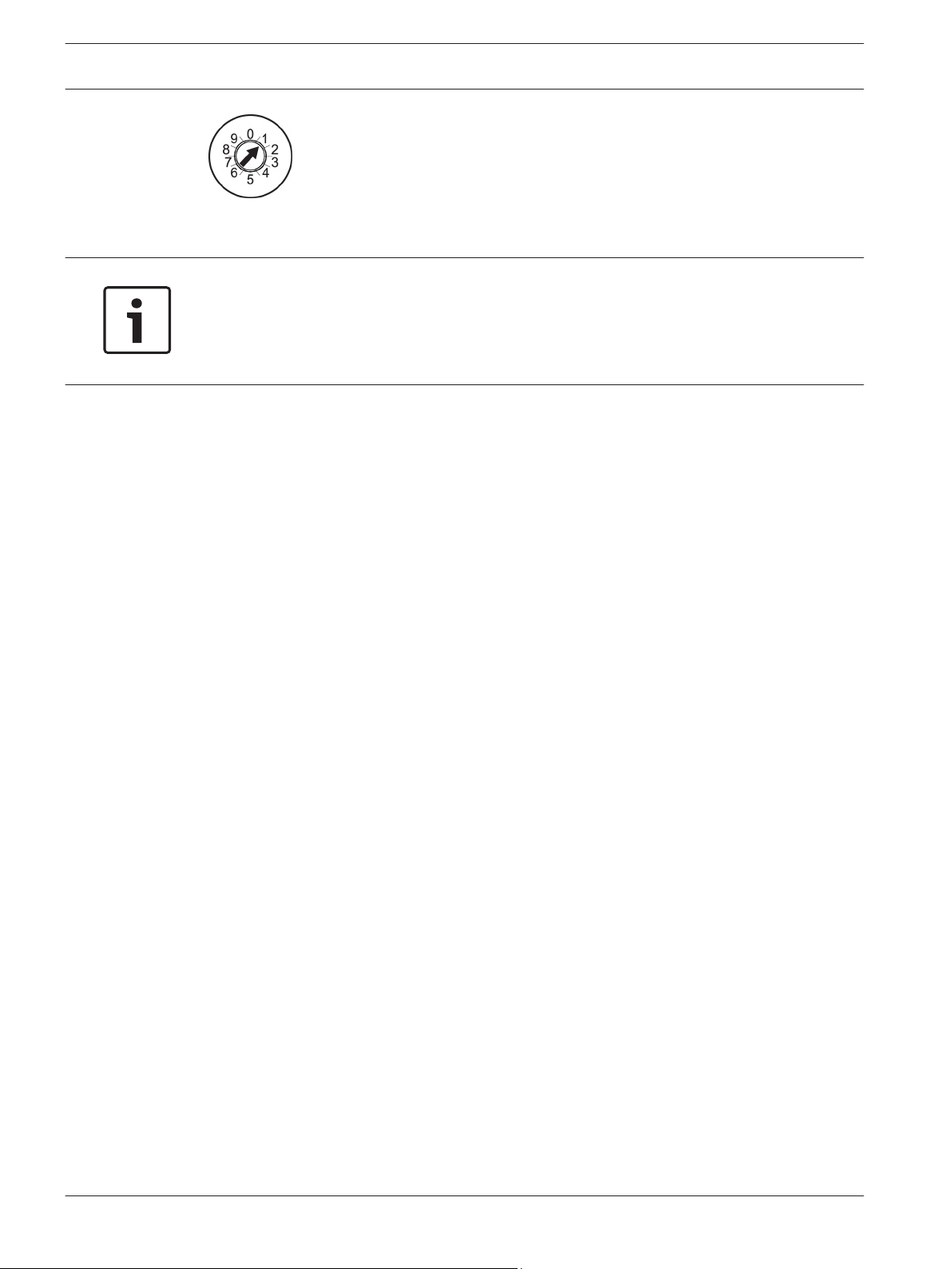
Figure 3.1: Address switch set to 1
Notice!
Inoperable RADION keyfob
If the RADION keyfob no longer operates as originally programmed, try resetting the receiver.
RF IDs remain active if previously enrolled, and will not have to be re-enrolled when resetting
the receiver.
Failure conditions
The following conditions describe the state of the keyfob when it no longer arms/disarms the
security system:
– The keyfob is correctly programmed in the control panel, and
– The receiver LED flashes when the keyfob is activated, but
– The expected action (arm/disarm) does not occur at the control panel.
Synchronizing the keyfob with the receiver
Perform the following steps to reset the receiver and restore arming/disarming functionality
for the keyfob.
Resetting the receiver:
1. Power off the receiver (or remove the receiver from its base).
2. Set the receiver address switch to 9.
3. Power on the receiver (or re-attach the receiver to its base).
4. LED indicates the firmware version. The LED turns on steady for a short time to reset the
receiver, and then turns off. Replace the receiver if the LED continues to flash.
5. Power off the receiver (or remove the receiver from its base).
6. Set the receiver address switch back to the original address setting.
7. Power on the receiver (or re-attach the receiver to its base).
8. Your system is ready for normal operation.
Base mounting installation
Some consideration and planning are required when locating a position to mount the base of
the receiver onto the desired surface. The base must be mounted in such a way that provides
plenty of accessible space to insert a flat-headed screwdriver, and remove the receiver cover
when maintenance and troubleshooting scenarios occur.
Because of the location of the opening mechanism on the side of the device, you will need
approximately 254 mm (10 in) of clearance on one side of the base to provide easy access to
the opening mechanism, and approximately 15 mm (0.6 in) of clearance on the opposite side
to compensate for the physical dimensions of the device cover. This should allow for adequate
space in which the device cover can be opened, and the cover removed, should the need
arise.
Other mounting considerations include;
– Minimum clearance above the location to compensate for the vertical sliding movement
to attach or remove the device from the base is: >30 mm (1.2 in).
3.3.2
14 en | RADION receiver SD RADION receiver SD
2015.10 | 08 | F.01U.261.834 Reference Guide Bosch Security Systems, Inc.
– Minimum clearance below the location where the base is mounted: >23 mm (0.9 in).
Wiring considerations
Notice!
Do not install long cable runs next to high-current power feeds. Keep cable lengths as short
as possible to minimize noise pickup.
Ensure that the wiring used meets the following specifications:
– Four-conductor unshielded 0.65 mm (22 AWG) to 2.0 mm (18 AWG) maximum.
– Wire length must not exceed 243 m (800 ft) from the control panel
R
Y
G
B
2
1
SDI Connector
SDI2 Connector
36
35
34
33
32
31
SDI
RED
POWER +
YELLOW
DATA BUS A
GREEN
DATA BUS B
s before servicing.
SDI2
RED
POWER +
YELLOW
DATA BUS A
GREEN
DATA BUS B
BLACK
COMMON
4
3
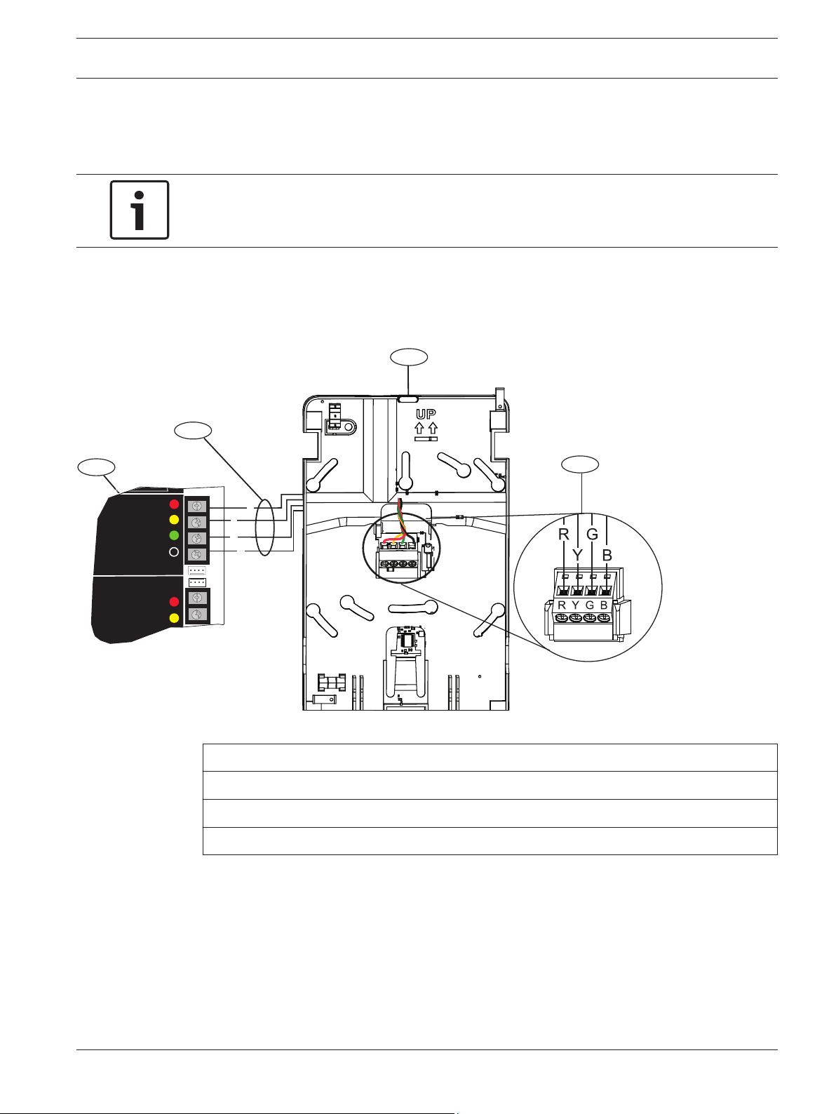
Figure 3.2: Wiring the receiver to an SDI2 compatible control panel
1 ᅳ SDI2 compatible control panel
2 ᅳ Terminal wiring
3 ᅳ RADION receiver SD mounting base
4 ᅳ Module terminal block
Programming wireless points in the control panel
After completing the physical installation of the RADION system, you must configure the
RADION points in order to establish communication between the RADION system and the
supported control panel. This can be accomplished by using one of two methods:
– Using Remote Programming Software (RPS) on a supported laptop computer, or
– Compatible keypad devices to enable your points
A “point” can be a detection device, or a group of devices connected to your security system.
3.3.3
3.3.4
RADION receiver SD RADION receiver SD | en 15
Bosch Security Systems, Inc. Reference Guide 2015.10 | 08 | F.01U.261.834
The first step to enable communication is to verify that the RADION transmitter is
programmed into the supporting control panel. This is achieved by configuring a point source
index as wireless.
RFID programming from a supported keypad is achieved by two methods;
– Through the point source/RFID menu options, or
– Enroll point RFID for wireless points – which uses the “Auto-Learn” methodology.
The preferred method of entering in the RFID number would be to enter it in manually via the
keypad – point source/RFID, or RPS. Doing so gives you greater control and security, while
reducing the risk of incomplete RFID programming.
Not every scenario can be documented regarding various supporting panels and keypads. The
workflow listed below is a generic representation of the programming/enablement process.
Refer to the Points Menu Parameters section inside the Keypad Installer Menu chapter of the
B5512/B4512 and/or D9412GV4/D7412GV4 v2.xx Series Installation and System Reference
Guides, or Points – Point Assignments in RPS Help File for more information.
Point source/RFID programming
A point’s source gives a description as to the physical location of the point for installation and
service personnel. Perform the following to program a source:
1. Using either RPS, or a supported keypad, access the Program Menu, and select the
Points menu option.
2. Select the Source menu option
3. Select the point source of the device you are programming.
4. Change the point source to the “wireless” option.
5. Save changes.
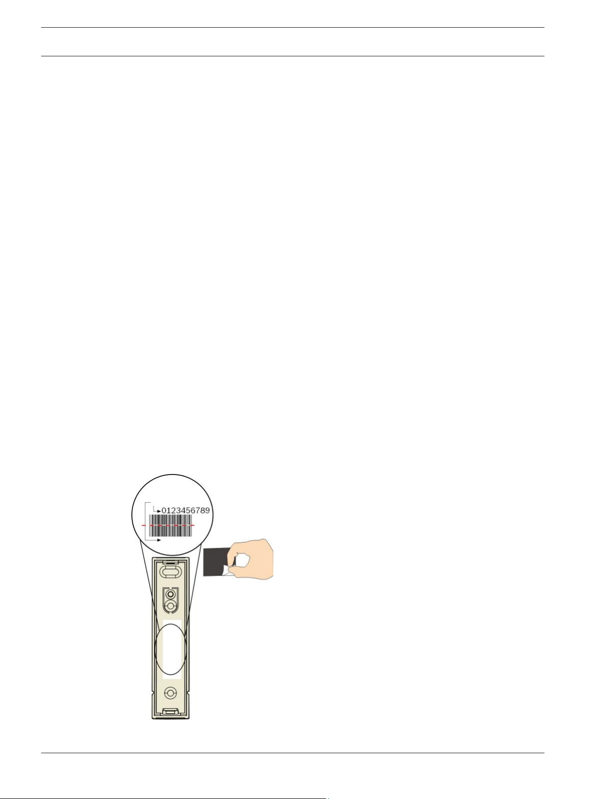
6. Select the RFID menu option to edit the RFID of each RADION device.
7. Manually enter in the unique RFID as it appears on the RFID sticker in the illustration
below. ID’s beginning with a zero may not display in the keypad UI, or RPS
8. Save changes and exit the menu.
The control panel is now enabled to receive wireless communication information from the
RADION transmitter.
Figure 3.3: RFID sticker example (RFDW-SM-A shown)
16
en | RADION receiver SD RADION receiver SD
2015.10 | 08 | F.01U.261.834 Reference Guide Bosch Security Systems, Inc.
Point indexes
Point indexes determine how points operate/respond to circumstances within a system.
Perform the following to program a point:
1. Using either RPS, or a supported keypad, access the Program Menu, and select the
Points menu option.
2. Select the point source of the device you are programming and select the wireless device
type. Ensure that it matches that of the physical device you are enrolling.
3. Assign the desired attributes of the point index (how the device will respond to various
circumstances).
4. Save changes and exit the menu.
Signal strength test (for repeaters)
Use the following procedure to test the frequency strength and range of the RADION system.
1. From the keypad, access the Wireless Menu, and select the Diagnostics menu option.
2. Select the RF Repeaters menu option.
3. Select the Signal menu option and choose the desired repeater. Various sub-categories
display including:
– Signal Strength
– Level
– Margin
4. When finished, exit the menu.
Enroll point RF ID for wireless points (Auto-learn mode)
A second option exists whereby new devices are discovered on the system. This option is
referred to as the “Auto Learn Mode” option. Auto Learn Mode is the process through which
the control panel identifies and enrolls new device RF ID’s that appear within the system. This
is achieved by the following:
– Keyfobs – when the keyfob buttons are pressed, then released.
– Motion detectors – when the battery is inserted, or if coverage pattern is disturbed by
someone walking through the coverage pattern field.
Notice!
The Auto Learn mode option is not recommended as the preferred method of entering in the
RF ID’s due to the potential of the RADION system picking up the first available RF ID it
detects. For optimal results, manually enter in the RF ID’s through the supported keypad, or
via RPS.
Enrolling a wireless point RF ID
Using a supported keypad, enroll the RF ID through the Wireless menu option. Use the
Wireless menu to add, replace, remove, and diagnose points and repeaters.
Perform the following to enroll in the RF ID:
1. From the keypad, access the Wireless Menu, and select the Points menu option. If
adding a repeater, select the Repeater menu option.
2. Select the option for enrolling a point RFID.
3. When asked, select the point source you are enrolling).
4. Initiate activity for the desired device (walk through the coverage pattern if enrolling a
motion detector, or press the button on the keyfob if enrolling a keyfob, open the door or
window if enrolling a contact). By doing so, the control panel recognizes the first RFID it
comes in contact with.
5. When the keypad or RPS shows Point Enrolled, exit out of the application.
3.3.5
RADION receiver SD RADION receiver SD | en 17
Bosch Security Systems, Inc. Reference Guide 2015.10 | 08 | F.01U.261.834
6. Verify the RFID displayed on the keypad matches the RFID sticker that appears on the
activated device.
Walk test (for motion detectors)
Use the following pattern testing procedure to test the detector range and functionality.
Notice!
Also see Control Panels (D9412GV4/D7412GV4 v2.00) SIA CP-01 Quick Reference Guide P/N: F.
01U.265.466, and/or Control Panels (B5512/B4512) SIA CP-01 Quick Reference Guide P/N: F.
01U.265.464.
Motion walk test
Remove and replace cover to activate a 90-sec Walk Test Mode. During this Test Mode, any
activity in the sensor’s coverage pattern will cause a transmitted alarm and LED activation.
Each alarm will also extend the Test Mode for an additional 90-sec. Walk Testing should be
done across the coverage pattern. The edge of the coverage pattern is determined by the first
flash of the LED. This may change slightly depending upon the sensitivity setting. Walk Test
the unit from both directions to determine the pattern boundaries. Although generally not
required, if masking is desired, the lens diagram shows the appropriate areas to be masked.
Use an opaque material (such as, electrical tape) to mask the desired areas.
Final test
While the detector is in the Walk Test Mode, turn on all heating and air conditioning sources
which would normally be active during the protection period. Stand away from the sensor and
outside the coverage pattern and watch for alarms. After setup and tests are completed, and
there has been no activity in the sensor’s coverage pattern for approximately 90-sec, the LED
will flash to indicate that the Walk Test mode is ending.
Maintenance
At least once a year, a walk test should be performed to verify the range and coverage for
proper operation.
Magnet walk test
Perform a magnet test to ensure proper functionality of the door and window contacts.
Magnet testing can be performed by opening or closing the door/window in which the magnet
is installed. In this test, you are verifying the distances of which the magnet engages and
disengages the transmitter.
Signal level and margin
The signal level and margin (ambient signal) of the RADION system is dependant on the
location in which the B810 receiver and transmitters communicating with it are installed.
Installing the receiver in an environment that has a lot of radio transmitter communication or
other exterior disturbances, may reduce the receiver signal strength and margin signal of the
B810 receiver.
Signal Level is a measure of how loudly a RADION receiver is hearing a message from a
RADION transmitter; this value is displayed as a percentage with a range of 0% - 99%.
Signal Margin is a measure of how well a RADION receiver is hearing a message from a
RADION transmitter given the current ambient noise levels, or ‘white noise’ at the receiver.
This value is displayed as a percentage with a range of 0% - 99%.
3.3.6
3.3.7
18 en | RADION receiver SD RADION receiver SD
2015.10 | 08 | F.01U.261.834 Reference Guide Bosch Security Systems, Inc.
Loading...