


 Loading...
Control Panels
B9512G/B8512G (B9512G-E/B8512G-E)
en UL Installation Guide
Control Panels Introduction | en 3
1 |
Introduction |
|
This section includes an introduction to documents for this product and other document- |
|
related instructions. |
1.1 |
About documentation |
This document contains instructions for a trained installer to properly install, configure, and operate this control panel, and optional peripheral devices. Review this document before beginning the installation to determine the hardware and wiring requirements for the features used.
(Bosch Security Systems, Inc. recommends that installers follow good wiring practices such as those descibed in NFPA 731, Standard for the Installation of Electronics Premises Security Systems.)
Throughout this document, the words “control panel” refer to all control panels covered by this document (B9512G/B8512G/B9512G-E/B8512G-E).
Notifications
This document uses Notices, Cautions, and Warnings to draw your attention to important information.
Notice!
These include important notes for successful operation and programming of equipment, or indicate a risk of damage to the equipment or environment.
Caution!
!These indicate a hazardous situation which, if not avoided, could result in minor or moderate injury.
Warning!
!These indicate a hazardous situation which, if not avoided, could result in death or serious injury.
Copyright
This document is the intellectual property of Bosch Security Systems, Inc. and is protected by copyright. All rights reserved.
Trademarks
All hardware and software product names used in this document are likely to be registered trademarks and must be treated accordingly.
1.1.1 |
Related documentation |
|
Control panel documents |
|
|
|
Control Panels (B9512G/B8512G) Release Notes * |
|
|
|
Control Panels (B9512G/B8512G) Installation and System Reference Guide (P/N: F01U303996)+ |
|
Control Panels (B9512G/B8512G/B5512/B4512/B3512) Owner’s Manual (English) (P/N: |
|
F01U307371)* + |
|
Control Panels (B9512G/B8512G) Program Entry Guide (P/N: F01U303998)+ |
|
Control Panels (B9512G/B8512G) UL Installation Guide+ (this document) (P/N: F01U304001)* |
|
+ |
|
|
|
|
Bosch Security Systems, Inc. |
UL Installation Guide |
2016.05 | 05 | F.01U.304.001 |

4 |
en | Introduction |
Control Panels |
|
|
|
Control Panels (B9512G/B8512G) SIA Quick Reference Guide (P/N: F01U304000)* +
Control Panels (B9512G/B8512G/B6512/B5512/B4512/B3512) ULC Installation Guide (P/N:
F01U321698)
*Shipped with the control panel.
+Located on the documentation CD shipped with the control panel.
Keypad documents
Basic Keypad (B915) Installation Guide (P/N: F01U297873)*
Two-line Alphanumeric Keypad (B920) Installation Guide (P/N: F01U265450)*
Fire Keypads (B925F/B926F) Installation Guide (P/N: F01U305193)*
Two-line Capacitive Keypad with Inputs (B921C) Installation Guide (P/N: F01U297887)*
ATM Style Alphanumeric Keypad (B930) Installation Guide (P/N: F01U265451)*
Touch Screen Keypad (B942/B942W) Installation Guide (P/N: F01U294527)*
*Shipped with the keypad.
Optional module documents
Octo-input Module (B208) Installation and Operation Guide (P/N: F01U265456)*
POPEX Module (B299) Installation Guide (P/N: F01U300043)*
Octo-output Module (B308) Installation and Operation Guide (P/N: F01U265458)*
Conettix Ethernet Communication Module (B426) Installation and Operation Guide (P/N:
F01U281208)* +
Plug-in Telephone Communicator (B430) Installation Guide Installation Guide (P/N:
F01U265454)*
Conettix Plug-in Cellular Communicator (B440) Installation and Operation Guide (P/N:
F01U265455)*
Conettix Plug-in CDMA Cellular Communicator (B441) Installation and Operation Guide (P/N: F01U282233)*
Conettix Plug-in GPRS Cellular Communicator (B442) Installation and Operation Guide (P/N: F01U283180)*
Conettix Plug-in HSPA+ Cellular Communicator (B443) Installation and Operation Guide (P/N: F01U283181)*
Conettix Plug-in Communicator Interface (B450) Installation and Operation Guide (P/N:
F01U300740)* +
Auxiliary Power Supply (B520) Installation and Operation Guide (P/N: F01U265445)*
Retrofit ZONEX Module (B600) Installation Guide (P/N: F01U300237)
RADION receiver SD (B810) Installation Guide (P/N: F01U261834)*
SDI2 Inovonics Interface Module (B820) Installation Guide (P/N: F01U265460)*
Access Control Module (B901) Installation Guide (P:/N: F01U300416)
Dual Class B Initiating Module (D125B) Installation Instructions (P/N: F01U036340)
2016.05 | 05 | F.01U.304.001 |
UL Installation Guide |
Bosch Security Systems, Inc. |

Control Panels Introduction | en 5
|
Multiplex Bus Interface (D8125MUX) Operation and Installation Guide (P/N: F01U034973) |
|||||||||||||||||||||||||||||
|
|
|
|
|
|
|
|
|
|
|
|
|
|
|
|
|
|
|
|
|
|
|
|
|
|
|
|
|
|
|
|
OctoPOPIT Module (D8128D) Installation Guide (P/N: F01U070537) |
|||||||||||||||||||||||||||||
|
|
|
|
|
|
|
|
|
|
|
|
|
|
|
|
|
|
|
|
|
|
|
|
|
|
|
|
|
|
|
|
Access Control Interface Module (D9210C) Installation and Operation Guide (P/N: |
|||||||||||||||||||||||||||||
|
F01U215232) |
|||||||||||||||||||||||||||||
|
|
|
|
|
|
|
|
|
|
|
|
|
|
|
|
|
|
|
|
|
|
|
|
|
|
|
|
|
|
|
|
*Shipped with the module. |
|||||||||||||||||||||||||||||
|
+Located on the documentation CD shipped with the module. |
|||||||||||||||||||||||||||||
1.2 |
Bosch Security Systems, Inc. product manufacturing dates |
|||||||||||||||||||||||||||||
|
Use the serial number located on the product label and refer to the Bosch Security Systems, |
|||||||||||||||||||||||||||||
|
Inc. website at http://www.boschsecurity.com/datecodes/. |
|||||||||||||||||||||||||||||
|
The following image shows an example of a product label and highlights where to find the |
|||||||||||||||||||||||||||||
|
manufacturing date within the serial number. |
|||||||||||||||||||||||||||||
|
|
|
|
|
|
|
|
|
|
|
|
|
|
|
|
|
|
|
|
|
|
|
|
|
|
|
|
|
|
|
|
|
|
|
|
|
|
|
|
|
|
|
|
|
|
|
|
|
|
|
|
|
|
|
|
|
|
|
|
|
|
|
|
|
|
|
|
|
|
|
|
|
|
|
|
|
|
|
|
|
|
|
|
|
|
|
|
|
|
|
|
|
|
|
|
|
|
|
|
|
|
|
|
|
|
|
|
|
|
|
|
|
|
|
|
|
|
|
|
|
|
|
|
|
|
|
|
|
|
|
|
|
|
|
|
|
|
|
|
|
|
|
|
|
|
|
|
|
|
|
|
|
|
|
|
|
|
|
|
|
|
|
|
|
|
|
|
|
|
|
|
|
|
|
|
|
|
|
|
|
|
|
|
|
|
|
|
|
|
|
|
|
|
|
|
|
|
|
|
|
|
|
|
|
|
|
|
|
|
|
|
|
|
|
|
|
|
|
|
|
|
|
|
|
|
|
|
|
|
|
|
|
|
|
|
|
|
|
|
|
|
|
|
|
|
|
|
|
|
|
|
|
|
|
|
|
|
|
|
|
|
|
|
|
|
|
|
|
|
|
|
|
|
|
|
|
|
|
|
|
|
|
|
|
|
|
|
|
|
|
|
|
|
|
|
|
|
|
|
|
|
|
|
|
|
|
|
|
|
|
|
|
|
|
|
|
|
|
|
|
|
|
|
|
|
|
|
|
|
|
|
|
|
|
|
|
|
|
|
|
|
|
|
|
|
|
|
|
|
|
|
|
|
|
|
|
|
|
|
|
|
|
|
|
|
|
|
|
|
|
|
Bosch Security Systems, Inc. |
UL Installation Guide |
2016.05 | 05 | F.01U.304.001 |
6 en | System overview Control Panels
2 |
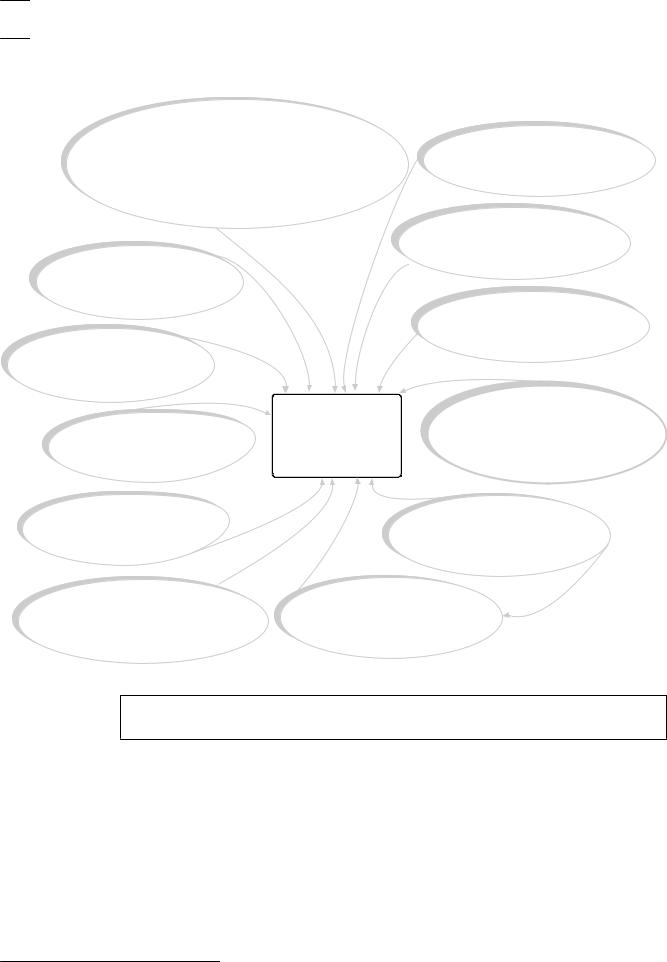
System overview |
|
|
B91X/B92X/B93X/B94X |
|
|
Use keypads* to operate |
B810 |
|
the control panel by area. |
|
|
RADION receiver SDs |
|
|
B9512 control panels support up to 32 areas. |
|
|
connect RADION wireless devices |
|
|
B8512 control panels support up to 8 areas. |
|
|
to the control panel. |
|
|
Each area can have its own account number |
|
|
|
|
|
or you can group together areas |
|
|
with a common account number. |
|
B820
SDI2 Inovonics Interface modules interface with an Inovonics
B208 wireless receiver. Octo-input modules allow
the addition of up to 8
input devices.
B426
The B426 provides off-board B299 communication over a network.
POPEX modules provide support for up to 100 POPIT devices over a single expansion loop.
|
B430 |
|
|
||
|
Plug-in Tephone Communicator |
|
B308 |
provides a single |
|
Octo-output modules allow |
telephone RJ-45 connector |
|
the addition of up to 8 |
to allow communication |
|
output devices. |
over telephone lines. |
|
B600 |
B44X |
|
The ZONEX modules allows |
||
Conettix Plug-In Cellular |
||
the connection of ZONEX |
||
Communicator allows |
||
expansion modules. |
||
communciation over |
||
|
||
|
a cellular network. |
|
B520 |
B450 |
|
Conettix Plug-In Communicator |
||
Auxiliary Power Supply modules |
||
Interface allows communciation |
||
expand power by connecting to |
||
over a cellular network through |
||
an SDI2 device bus or |
||
the SDI2 bus. |
||
other 12 volt devices. |
||
|
*Up to 8 of the keypads can be models D1260, D1257/D1257RB, D1256/D1256RB, or D1255/D1255R/D1255RB on the SDI bus (SDIx configured as SDI).
2016.05 | 05 | F.01U.304.001 |
UL Installation Guide |
Bosch Security Systems, Inc. |
Control Panels Control panel installation | en 7
3 Control panel installation
This section explains how to mount the control panel enclosure, how to mount the control panel into the enclosure, and provides an overview of how to wire modules to the control panel.
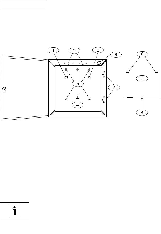
Enclosure overview
Before you begin, review the overview figure:
Figure 3.1: Enclosure and control panel mounting overview
Callout Description |
Callout Description |
|||
|
|
|
|
|
1 |
Mounting skirt attachment hooks (2) |
5 |
Enclosure mounting holes (5) |
|
|
|
|
|
|
2 |
Module mounting three-hole pattern (4) |
6 |
Mounting skirt attachment holes (2) |
|
|
|
|
|
|
3 |
Tamper switch mounting location |
7 |
Back of the control panel mounting skirt |
|
|
|
|
|
|
4 |
Mounting skirt screw location (1) |
8 |
Mounting skirt screw tab |
|
|
|
|
|
|
3.1 |
Install the enclosure |
|
|
|
Refer to Enclosures to determine if the application requires a specific enclosure.
Installing the enclosure:
1.Remove any knockouts prior to installing the control panel.
2.Mount the enclosure in the desired location. Use all enclosure mounting holes. Refer to the mounting instructions supplied with the selected enclosure.
3.Pull the wires into the enclosure.
4.Optionally install the supplied point label chart on the inside of the enclosure door.
Notice!
Electromagnetic interference (EMI) can cause problems on long wire runs.
Bosch Security Systems, Inc. |
UL Installation Guide |
2016.05 | 05 | F.01U.304.001 |

8 en | Control panel installation Control Panels
3.2 |
Install the control panel |
|
|
This section includes instructions to mount the control panel in the enclosure, connect earth |
|
|
ground, and make other control panel connections. |
|
3.2.1 |
Mount the control panel |
|
|
Refer to the figure Enclosure overview, page 7. |
|
|
Mounting the control panel: |
|
|
1. |
Place the control panel over the inside back of the enclosure, aligning the large |
|
|
rectangular openings of the mounting skirt with the enclosure mounting attachment |
|
|
hooks. Slide the control panel down so that it hangs on the hooks. |
|
2. |
Remove the tape from the #6 x 1/4-in screw in the mounting skirt screw tab on the |
|
|
control panel. The screw passes through the mounting tab and into the skirt mounting |
|
|
hole in the enclosure. |
|
3. |
Tighten the screw to secure the control panel in the enclosure. |
|
|
|
|
Notice! |
|
|
Connect earth ground to the control panel before making any other connections. |
|
|
|
|
3.2.2 |
Connect earth ground |
|
|
To help prevent damage from electrostatic discharges or other transient electrical surges, |
|
connect the system to earth ground before making other connections. The  icon (Terminal 10) indicates the earth ground terminal. Use a recommended earth ground reference, such as a grounding rod or a cold water pipe. Make the connection using 14 AWG (1.8 mm) to 16 AWG (1.5 mm) wire.
Notice!
Do not use telephone or electrical ground for the earth ground connection. Do not connect other control panel terminals to earth ground.
Caution!
!Avoid electrostatic discharge. Always touch the earth ground connection with the  icon first, before beginning work on the control panel.
3.2.3 Ground Fault Detect enable
To meet UL 864 requirements, enable Ground Fault Detect.
A ground fault is a circuit impedance to ground sufficient to result in the annunciation of a trouble condition.
The control panel has a ground fault detection circuit that when enabled, detects ground faults on Terminals 1 to 9 and 11 to 30.
If a ground fault condition occurs, the keypads annunciate a ground fault and the control panel transmits a trouble message.
When the control panel recognizes that the ground fault condition is corrected, and remains corrected for between 5 to 45 consecutive seconds, the control panel clears the fault from the keypad display and sends a restoral report.
The control panel detects ground fault at ≤ 300 Ω.
2016.05 | 05 | F.01U.304.001 |
UL Installation Guide |
Bosch Security Systems, Inc. |

Control Panels Control panel installation | en 9
|
Enable Ground Fault Detect |
|
To enable fault detection, use RPS. Refer to RPS Help. |
3.2.4 |
Ground fault detection troubleshooting |
|
Measure earth ground (Terminal 10) and common (Terminal 9) to determine whether the |
|
control panel has the necessary -2.1 V decay to 0. |
Measuring and comparing voltage for ground fault detection:
1.Set your digital voltmeter (DVM) to measure VDC.
2.Connect the red DVM lead to control panel Terminal 10, and the black DVM lead to Terminal 9.
3.Compare this voltage to the following table:
Control panel voltage at Terminals 9 and 10) |
Terminal potentially causing ground fault |
|
|
~ 0 VDC |
4, 9, 12, 15, 17, 21 |
|
|
~ 13.65 VDC |
5, 6, 7, 8, 26, 30 |
|
|
~ 2.51 VDC |
11, 13, 14, 16, 17, 19, 20, 22 |
|
|
~ 2.44 to 3.2 VDC |
24 |
|
|
~ 10.9 to 11.2 VDC |
25 |
|
|
~ 7.2 VDC |
28 |
|
|
~ 5.8VDC |
29 |
|
|
~ 7.35 VDC |
1, 2 |
|
|
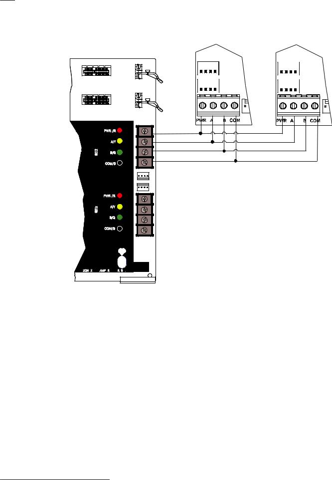
3.3 Control panel to module wiring overview
In the following sections, this document provides instructions for wiring devices to your control panel. You can use interconnect or terminal wiring.
If SDIx is configured for SDI2, use either SDI2 bus.
Using terminal wiring
For terminal wiring, use 18 AWG to 22 AWG (1.02 mm to 0.65 mm) wire.
Bosch Security Systems, Inc. |
UL Installation Guide |
2016.05 | 05 | F.01U.304.001 |
10 |
en | Control panel installation |
Control Panels |
|
|
|
SDI2 devices daisy chained with terminal wiring
MOD-2
MODULE RELEASE
ting |
SDI2 |
olice |
|
ire |
|
|
SDIx |
ZONEX
ZONEX
|
MOD-1 |
PWR+/R |
30 |
A/Y |
29 |
B/G |
28 |
COM/B 27 |
|
|
SDI2 |
|
SDIx |
PWR+/R |
26 |
A/Y |
25 |
B/G |
24 |
COM/B |
23 |
TAMPER |
RESET |
TMPR |
|
Using interconnect wiring
Interconnect wiring connectors parallel the SDI2 terminals (27 through 30 (or 23 through 26 if configured for SDI2)). In installations with multiple SDI2 modules, using interconnect wiring makes the installation quicker and easier than using terminal strip wiring. You use any combination of terminal and interconnect wiring to wire multiple modules in parallel, but do not wire a single module to the control panel using both terminal and interconnect wiring. The interconnect wiring connectors are "keyed" (interconnect wiring plug can fit in only one direction).
2016.05 | 05 | F.01U.304.001 |
UL Installation Guide |
Bosch Security Systems, Inc. |
Control Panels |
Control panel installation | en |
11 |
|
|
|
SDI2 devices daisy chained with interconnect wiring
MOD-2
MODULE RELEASE
MOD-1
olice |
ting |
ire |
|
PWR+/R |
30 |
|
A/Y |
29 |
SDI2 |
B/G |
28 |
COM/B 27
|
PWR+/R |
26 |
SDIx |
A/Y |
25 |
|
|
B/G 24
COM/B 23
SDI2 |
SDIx |
ZONEX |
TAMPER |
RESET |
ZONEX TMPR
Bosch Security Systems, Inc. |
UL Installation Guide |
2016.05 | 05 | F.01U.304.001 |
12 en | Power supply Control Panels
4 |
Power supply |
|
This section provides information on installing and maintaining primary power, batteries, and |
|
auxiliary power. |
4.1 |
Primary (AC) power |
|
1 |
2 |
|
The control panel uses a 16.5 VAC, 40 VA, internally-fused transformer (D1640) for its primary |
|
|
power source. The control panel draws 190 mA when idle and 265 mA when in the alarm |
|
|
state. |
|
|
The auxiliary power available for powered devices is 1.4 A. |
|
|
Surge protection |
|
|
Transient suppressors and spark gaps protect the circuit from power surges. This protection |
|
|
relies on the ground connection at the earth ground terminal (Terminal 10), marked with the |
|
|
icon. Ensure that you connect the terminal to a proper ground. |
|
|
Refer to Connect earth ground, page 8. |
|
|
AC power fail |
|
|
The system indicates an AC power failure when the transformer input terminals do not have |
|
|
sufficient voltage. The AC Fail Time parameter sets the amount of time without AC power |
|
|
before the control panel reports the failure, and the amount of time after the power returns |
|
|
before the control panel reports restored power. |
|
|
When the control panel loses AC power long enough for the battery to become low, the |
|
|
control panel adds a Battery Low event to the event log. If the battery continues to discharge |
|
|
below the load shed threshold, the system ceases to operate and generates no further events. |
|
4.1.1 |
Install the transformer |
|
|
|
|
|
Caution! |
|
|
Do not short-circuit the terminals of the transformer: Shorting the terminals opens the |
|
!internal fuse, causing permanent failure. Connect the transformer to the control panel's AC power terminals before plugging it into the power source.
Notice!
Plan ahead
Route telephone, SDI2 bus wiring, and sensor loop wiring away from any AC conductors, including the transformer wire. AC wiring can induce noise and low level voltage into adjacent wiring.
1.Use 18 AWG (1.02 mm) wire minimum (12 AWG [2 mm] maximum) and connect the transformer to the control panel. Make the wire length as short as possible. Do not exceed 50 ft (15 m).
2.Connect the wire to the control panel.
3.Connect the wire to the transformer.
4.Plug the transformer into an unswitched, 120 VAC, 60 Hz power outlet only.
5.Secure the transformer to the outlet with the screw provided (not applicable in Cananda).
2016.05 | 05 | F.01U.304.001 |
UL Installation Guide |
Bosch Security Systems, Inc. |
Control Panels Power supply | en 13
D8004 Transformer Enclosure required for fire systems
Use the D8004 Transformer Enclosure for the D1640 Transformer in fire and combined fire and burglary applications.
Notice!
Check with the Authority Having Jurisdiction (AHJ) about mounting transformers on specific circuits.
4.2 Secondary (DC) power
|
4 |
5 |
|
A 12 V sealed lead-acid rechargeable battery (such as the D126/D1218) supplies secondary |
|
|
power to maintain system operation during interruptions of primary (AC) power. |
|
|
|
|
|
Notice! |
|
|
Use sealed lead acid batteries only |
|
|
The charging circuit is calibrated for lead-acid batteries. Do not use gel-cell or NiCad |
|
|
batteries. |
|
|
|
|
|
Extra batteries |
|
|
To increase battery back-up time, connect a second 12 V battery in parallel to the first battery. |
|
|
Use a D122/D122L Dual Battery Harness to ensure proper and safe connection. |
|
|
Refer to Standby battery requirements and calculations. |
|
|
D1218 Battery |
|
|
The D1218 is a 12 V, 18 Ah battery for use in applications requiring extended battery standby |
|
|
time. The control panel does not support more than 38 Ah of battery. |
|
4.2.1 |
Install the battery |
|
|
1. |
Place the battery upright in the base of the enclosure. |
|
2. Locate the red and black leads supplied in the hardware pack. |
|
|
3. |
Connect the black battery lead to Terminal 4 and then to the negative (-) side of the |
|
|
battery. |
|
4. |
Connect the red battery lead to Terminal 5, and then to the positive (+) side of the |
|
|
battery. |
Warning!
High current arcs are possible. The positive (red) battery lead and Terminal 5 can create high
!current arcs if shorted to other terminals or the enclosure. Use caution when working with the positive lead and Terminal 5. Always disconnect the positive (red) lead from the battery before removing it from Terminal 5.
Caution!
The battery terminals and wire are not power limited. Maintain a 0.250 in (6.4 mm) space
!between the battery terminals, battery wiring, and all other wiring. Battery wiring cannot share the same conduit, conduit fittings, or conduit knockouts with other wiring.
Bosch Security Systems, Inc. |
UL Installation Guide |
2016.05 | 05 | F.01U.304.001 |

14 en | Power supply |
Control Panels |
|
|
Non-power-limited wiring
1 |
2 |
|
3
4
BATTERY STATUS
Off: Normal
On: Missing
Quick Flash: Low
Slow Flash:
Charging
Low 12.1 VDC
Load Shed 10.2 VDC
Do not connect to a receptacle controlled by
aswitch.
1CLASS 2
16.5 VAC 40 VA 60 HZ
2TRANSFORMER
|
+ AUX POWER |
All exte |
|
|
|
|
|
|
|
|
|
|
|
3 |
Require |
|
|
|
|
|
|
|
|
|
|
|
|
|
|
POWER SUPPL |
|
|
|
|
|
|
|
|
|
|
|
4 |
BATTERY ( - ) |
The Power S |
|
|
|
|
|
|
|
|
|
|
|
|
|
refer to the B |
|
|
|
|
|
|
|
|
|
|
|
5 |
BATTERY ( + ) |
Battery: Replace every 3 to |
|
|
|
|
|
|
|
|
|
|
|
5 years with one or two |
|
|
|
|
|
|
|
|
|
|
|
||
|
|
Model D126 or D1218 12V |
|
|
|
|
|
|
|
|
|
|
|
|
OUTPUT |
Lead Acid Batteries. |
|
|
|
|
|
|
|
|
|
|
|
6 |
|
|
|
|
|
|
|
|
|
|
|
|
|
|
A (1) |
The system is intended |
|
|
|
|
|
|
|
|
|
|
|
|
|
panel has been approv |
|
|
|
|
|
|
|
|
|
|
|
7 |
OUTPUT |
RevPol. |
|
|
|
|
|
|
|
|
|
|
|
|
B (2) |
WARNING! |
|
|
|
|
|
|
|
|
|
|
|
|
|
|
|
|
|
|
|
|
|
|
|
|
|
|
OUTPUT |
To prevent risk of shock, |
|
|
|
|
|
|
|
|
|
|
|
8 |
disconnect AC power and |
|
|
|
|
|
|
|
|
|
|
||
|
C (3) |
communication lines before |
|
|
|
|
|
|
|
|
|
|
|
|
|
servicing. |
|
|
|
|
|
|
|
|
|
|
|
9 |
COMMON |
|
ON-BOARD POINTS |
|
|
|
|
|
|
|
|
|
|
|
|
|
|
|
Owner I |
|
|
|
|
|
|
|
|
10 |
EARTH GROUND |
|
|
be removed by |
|
|
|
|
|
|
|||
|
|
|
|
|
|
|
|
|
|
|
|||
WARNING! |
WARNING! |
|
|
Voltage Ranges: Open 3.7 - 5.0 VDC, |
|
|
|
|
|||||
|
|
|
|
|
|
|
|
|
|
|
|||
Multi-Battery |
Incorrect wiring will |
|
|
1 k End-of-line-Resistors Required (P/N 15093130-004), |
|
|
|||||||
installation requires |
damage this |
|
|
|
|
|
|
|
|
|
|
|
|
Model D122 or D122L |
equipment. |
Point 1 |
Point 2 |
|
Point 3 |
Point 4 |
|
Point 5 |
Point 6 |
Point 7 |
Point 8 |
|
|
Dual Battery Harness. |
Devices powered by |
|
|
|
|
|
|
|
|
|
|
|
|
Improper installation |
any output must be |
|
|
|
|
|
|
|
|
|
|
|
|
can be a fire hazard. |
supervised. |
11 |
12 |
13 |
14 |
15 |
16 |
17 |
18 |
19 20 |
21 |
22 |
|
USB POWER |
|
|
B |
|
|
|
STATUS |
L |
|
A |
|
|
|
|
I |
|
S |
|
|
|
|
|
E |
|
|
|
|
|
N |
|
|
|
|
|
|
K |
|
T |
|
|
|
|
USB |
ETHERNET |
POINT 1 COM |
POINT 2 POINT 3 COM |
POINT 4 |
POINT 5 COM POINT 6 POINT 7 COM POINT 8 |
|
|
|
|
|
5
6
Figure 4.1: Non-power-limited wiring
Callout Description
1 Conduit required for use with external batteries
2 Battery wires
3 0.25 in (6.4 mm) minimum. To ensure proper spacing, use tie-wraps or similar devices to secure wires.
4 Output wires
5 Sensor loop wires
6 12 V sealed lead-acid rechargeable battery (D126/D1218)
|
Charge the battery |
|
Connect the battery and then the transformer to allow the control panel to charge the battery |
|
while you complete the installation. |
4.2.2 |
BATTERY STATUS LED |
|
The control panel includes one BATTERY STATUS LED with 4 LED patterns to indicate the |
|
battery status. |
2016.05 | 05 | F.01U.304.001 |
UL Installation Guide |
Bosch Security Systems, Inc. |
Loading...