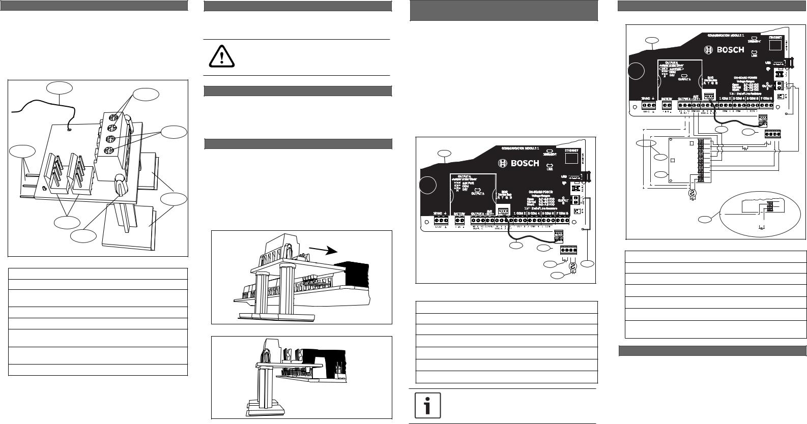
Bosch B201 Installation Manual

1 | Overview
The B201 2-wire Powered Loop Module provides a single powered initiating device circuit. The module supports 12 V compatible 2-wire smoke detectors. The B201 also supports connecting burg devices to the control panel.
The module connects to the control panel on-board inputs (using points 7 and 8 is recommended). Terminals A and COM are a direct connection (pass-thru) to point 7, and terminals B and PWR are a powered loop through point 8.
|
1 |
|
|
|
2 |
|
|
|
|
|
|
|
|
RESET |
|
|
3 |
|
|
SMOKE |
|
|
|
|
|
|
|
|
|
7 |
|
|
SMOKE |
PWR |
|
|
|
B |
|||
|
|
THRU |
|
||
|
|
|
|
COM |
|
|
|
|
- |
|
|
|
|
|
PASS |
|
|
B |
|
|
A |
||
|
|
|
|
||
COM |
|
|
|
|
|
A |
|
|
|
|
4 |
|
|
|
|
|
|
|
|
6 |
|
|
|
|
|
5 |
|
|
|
Figure 1.1: Module overview (with standoffs installed)
Callout ― Description
1 ― Smoke reset wire
2 ― Wiring terminals (to smoke detector, burg device, or D132A)
3 ― Non-powered terminals, direct pass-thru of point 7
4 ― Standoffs with adhesive pads (shown installed)
5 ― Standoff lock (positioned fully on top of the module board when properly installed)
6 ― Interconnect wiring connectors (to control panel or other modules)
7 ― Connection pins (to control panel terminal block)
2 | Installation
The module installs using the connection pins. The standoffs with adhesive pads (included) help secure the module in the enclosure.
CAUTION!
Remove all power (AC and battery) before making any connections. Failure to do so might result in personal injury and/or equipment damage.
2.1 | Install the standoffs
Remove the supplied standsoffs from packaging and gently insert the locking end of the standoffs through the holes as shown in Figure 1.1. Press the standoffs into the board until they security lock in place.
2.2 | Connect the module
Use the connection pins to connect the module to the desired inputs on the control panel (inputs 7 and 8 recommended).
1.Remove the backing from the standoffs to reveal the adhesive.
2.Align the module connection pins to the desired inputs. Refer to Figure 2.1.
3.Slide the module so that the connection pins are fully inserted. Refer to Figure 2.2.
4.Gently apply pressure to the standoffs to secure the adhesive to the enclosure.
Figure 2.1: Installing the module
Figure 2.2: Module installed on the control panel
2.3 | Wire to the control panel and a 2-wire smoke detector
Complete a standard installation by wiring the module. Use the supplied interconnect cable to wire to the control panel. Interconnect wiring parallels the PWR, A, B, and COM terminals on the terminal strip.
Refer to Figure 2.3.
1.Connect the smoke reset wire to OUTPUT B or C on the control panel. By default, OUTPUT C is programmed for Reset Sensors.
2.For power, connect the interconnect cable (included) from the module interconnect connector to the control panel interconnect connector.
3.Connect a 1 kΩ EOL resistor (supplied with the control panel)to A and COM, and connect the detector to B and PWR. Use a 1.8 kΩ resistor.
1
o |
|
|
A |
COM |
B |
|
|
SMOKE RESET |
2 |
3 |
|
|
|
|
|
PASS-THRU |
SMOKE |
|
A COM |
B PWR |
|
4 |
6 |
5
Figure 2.3: Wiring to the control panel and smoke detector
(B5512 shown)
Callout ― Description
1 ― Control panel
2 ― Interconnect wiring
3 ― Module
4 ― 1 kΩ EOL resistor (P/N: F01U026703)
5 ― 1.8 kΩ EOL resistor (P/N: F01U009011)
6 ― Smoke reset wire
NOTICE!
When connecting multiple SDI2 modules, you can use the unused interconnect connector to wire modules in series.
2.4 | Wire with a D132A
For installations requiring a D132A, refer to Figure 2.4.
1
o |
|
|
A |
COM |
B |
RESET
SMOKE
|
|
2 |
3 |
|
|
|
|
|
|
|
|
|
PASS-THRU |
SMOKE |
|
TRBL PT |
|
A COM |
B PWR |
|
- |
|
|
|
|
TRBL PT |
|
|
|
|
+ |
|
1 kΩ EOL |
|
|
REVERSE |
|
|
|
|
|
|
|
|
|
TRIGGER |
|
|
|
5 |
AUX-PWR |
|
|
|
AUX+PWR |
|
|
|
|
|
FIRE PT |
|
|
|
|
- |
|
|
|
|
FIRE PT |
|
|
|
4 |
+ |
|
|
|
DETECTOR |
|
|
|
|
|
- |
|
|
|
|
DETECTOR |
|
|
|
|
+ |
|
|
|
|
1.8 kΩ Smoke EOL |
|
|
DETECTOR |
|
|
|
|
- |
|
|
|
|
DETECTOR |
|
|
|
|
+ |
6


1.8kΩ Smoke EOL
Figure 2.3: Wiring with a D132A (B5512 shown)
Callout ― Description
1 ― Control panel
2 ― Interconnect wiring
3 ― B201
4 ― D132A
5 ― Wiring for Pulsing or Temporal Code 3 (optional)
6 ― Proper wiring from the D132A to the 2-wire smoke when configured with optional wiring (callout 5)
3 | Supervision
The powered loop uses a 1.8 kΩ EOL for loop supervision. The EOL also supervises the module because removal puts the point into trouble.
 Loading...