


B450-C
Table of contents
 Loading...
Conettix Plug-in Communicator Interface
B450
en Installation and Operation Guide


Conettix Plug-in Communicator
Interface
Table of contents
Table of Contents | en 3
1
2
2.1 About documentation 5
2.2 Bosch Security Systems, Inc. product manufacturing dates 5
2.3 Installation workflow 6
3
3.1 Module overview 7
3.2 B450 cellular interface compatibility 8
3.3 Bus address settings overview 9
4
4.1 Setting the bus address 11
4.2 Insert the communication module 12
4.2.1 Insert the B44x communication module (required and available separately) 13
4.2.2 Insert the B44x communication module with SIM card (required and available
4.3 Mount the module in the enclosure 14
4.3.1 Mount and wire the tamper switch (option for SDI2 bus only) 15
4.4 Install and mount the plug-in communicator antenna 16
4.5 Wire to the control panel 16
4.5.1 Wire to an SDI2 control panel 17
4.5.2 Wire to an SDI control panel 18
4.5.3 Wire to an option bus control panel 19
5
5.1 Configuration for SDI2 control panels 20
5.1.1 Configuring and viewing status from RPS 20
5.2 Use USB to configure the B450 26
5.2.1 Install a communication program 28
5.2.2 Log into the USB interface 32
5.2.3 USB Main menu 34
5.2.4 USB menu structure 35
5.2.5 USB menu 36
5.3 Short Message Service (SMS) configuration 49
5.3.1 Use SMS to configure the B450 49
5.4 Firmware Update page 52
6
6.1 USB menu access disabled 56
6.2 LED status indicators 56
6.3 Show the firmware version 60
6.4 SIM card 60
6.5 Diagnostic log 60
6.6 Understanding network polling 61
6.7 Control panel programming using cellular 61
7
7.1 Technical specification 62
7.2 Certifications 64
Safety 4
Introduction 5
System overview 7
Installation 11
13
separately)
Configuration 20
Maintenance and troubleshooting 56
Specifictions and certifications 62
Bosch Security Systems, Inc. Installation and Operation Guide 2014.12 | 06 | F.01U.300.740
!
4 en | Safety
Conettix Plug-in Communicator
Interface
1
Safety
ESD Precaution
Please note that while the B450 comes in a plastic case, and is protected from ESD, the plugin cellular communicator (B44x) does not. All plug-in cellular communicator components may
potentially be exposed to finger touches - therefore extra attention must be paid to ESD
(electrostatic discharge) precaution. Make sure there is no static interference when using the
board. Appropriate ESD protections must be taken and wearing electrostatic equipment is
recommended, such as anti-static wrist strap.
ESD damage can range from subtle performance degradation to complete device failure.
Precision integrated circuits may be more susceptible to damage because very small
parametric changes could cause the device not to meet its published specifications.
Warning!
Failure to follow these instructions can result in a failure to initiate alarm conditions. Bosch
Security Systems, Inc. is not responsible for improperly installed, tested, or maintained
devices. Follow these instructions to avoid personal injury and damage to the equipment.
Notice!
Inform the operator and the local authority having jurisdiction (AHJ) before installing the
module in an existing system.
Disconnect all power to the control panel before installing the module.
2014.12 | 06 | F.01U.300.740 Installation and Operation Guide Bosch Security Systems, Inc.

Conettix Plug-in Communicator
Interface
Introduction | en 5
2
2.1
2.2
Introduction
This document supports the B450 with firmware version v3.02
About documentation
Copyright
This document is the intellectual property of Bosch Security Systems, Inc. and is protected by
copyright. All rights reserved.
Trademarks
All hardware and software product names used in this document are likely to be registered
trademarks and must be treated accordingly.
Bosch Security Systems, Inc. product manufacturing dates
Use the serial number located on the product label and refer to the Bosch Security Systems,
Inc. website at http://www.boschsecurity.com/datecodes/.
Bosch Security Systems, Inc. Installation and Operation Guide 2014.12 | 06 | F.01U.300.740
!
6 en | Introduction
Conettix Plug-in Communicator
Interface
2.3
Installation workflow
To install and configure the module, use the workflow below and follow in sequential order
from top to bottom, checking off each box as you complete a step.
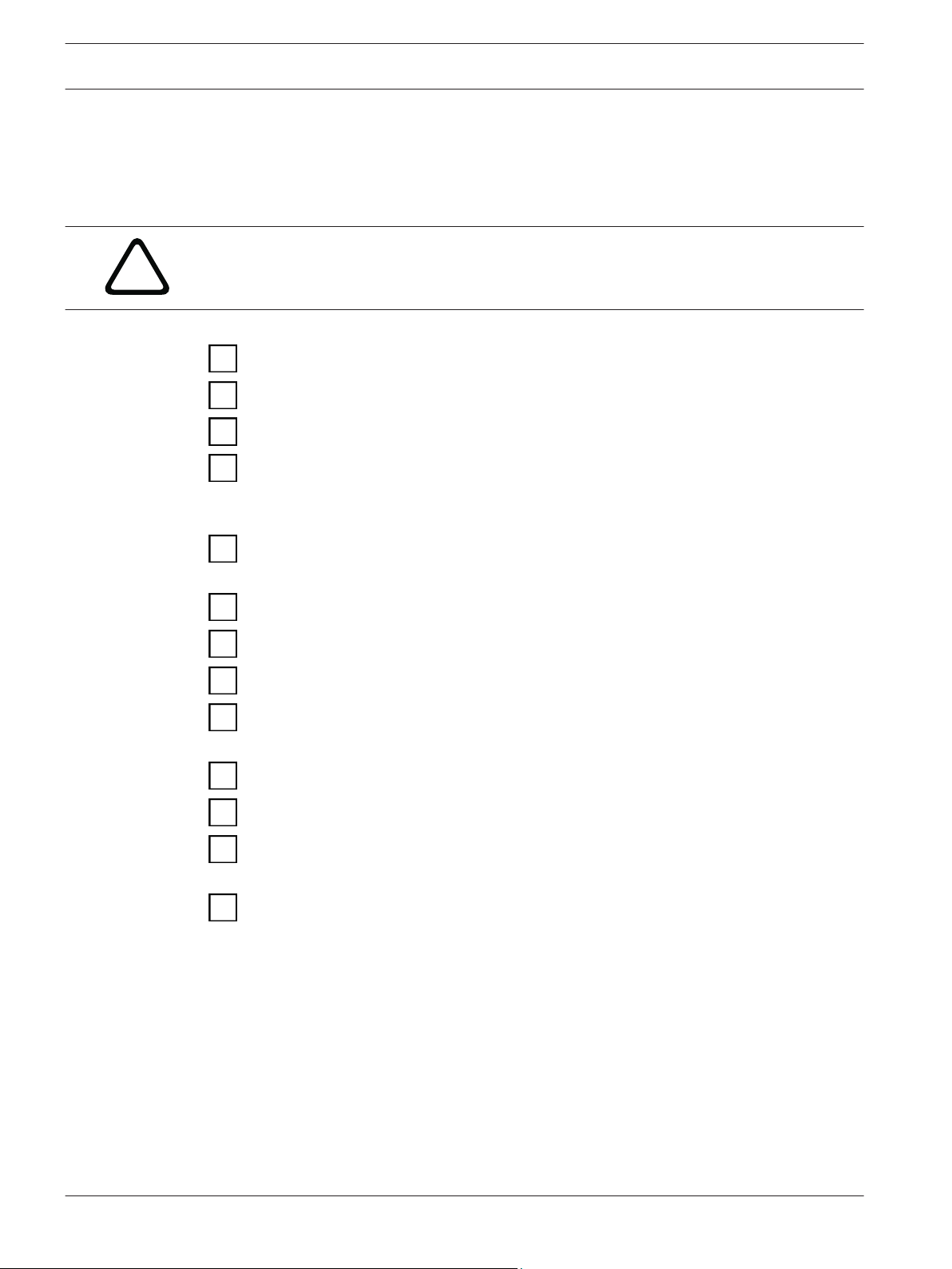
Caution!
Always power down the control panel when connecting a module. To power down the control
panel, unplug the transformer and disconnect the battery.
Plan the installation of the B450 Conettix Plug-in Communicator Interface
Unpack the device contents
Power down the system
Select the bus address value for the compatible control panel (This will automatically
configure the module to work with a compatible control panel. Refer to Setting the bus
address, page 11)
Insert the desired plug-in communicator into the B450 (Refer to Insert the communication
module, page 12)
Mount the B450 into the enclosure (Refer to Mount the module in the enclosure, page 14)
Wire the B450 to a compatible control panel (Refer to Wire to the control panel, page 16)
Power up the system
Install a communication program (if required) (Refer to Install a communication program,
page 28)
Configure the communication module (non SDI2 control panels)
Verify LED activity
Review signal strength on the cellular communicator. Refer to your cellular communicator
Installation Guide for more information on signal strength.
Installation is complete
2014.12 | 06 | F.01U.300.740 Installation and Operation Guide Bosch Security Systems, Inc.
1
2
7
5
6
3
4
8
9
Conettix Plug-in Communicator
Interface
System overview | en 7
3
System overview
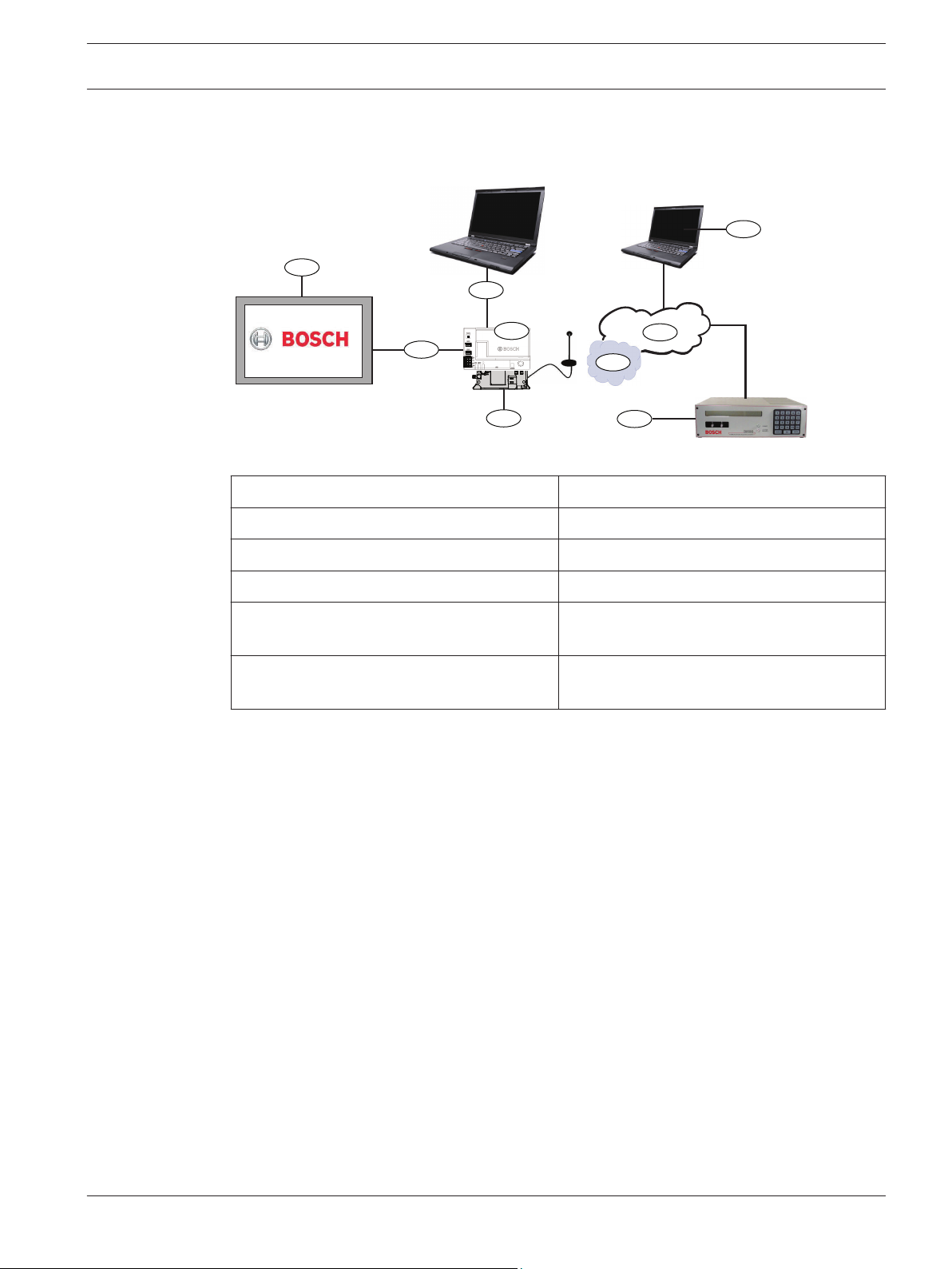
Refer to the graphic below for the complete B450 system configuration.
B450 system connections overview
Callout ᅳ Description
1 ᅳ Compatible Bosch control panel 6 ᅳ Cellular carrier network
2 ᅳ Panel data bus (SDI2, SDI, or Option) 7 ᅳ Internet/LAN/WAN
3 ᅳ B450 Plug-in Communicator Interface 8 ᅳ Remote Programming Workstation
Callout ᅳ Description
3.1
4 ᅳ USB connection for B450 configuration 9 ᅳ Compatible IP receiver (Bosch D6100IPv6
shown)
5 ᅳ B44x Plug-in Cellular Communicator
(available separately)
Module overview
The B450 Conettix Plug-in Communicator Interface (wired to a compatible control panel) is a
four-wire powered SDI2, or SDI device that provides two-way communication over commercial
cellular networks using a plug-in communicator.
The B450 Conettix Plug-in Communicator Interface bus address switch determines the bus
address of the device. When required, configuration of the module is managed through the
control panel, a local USB connection, or using SMS.
Bosch Security Systems, Inc. Installation and Operation Guide 2014.12 | 06 | F.01U.300.740
1
8
6
2
9
10
3
7
5
4
TX
RX
8 en | System overview
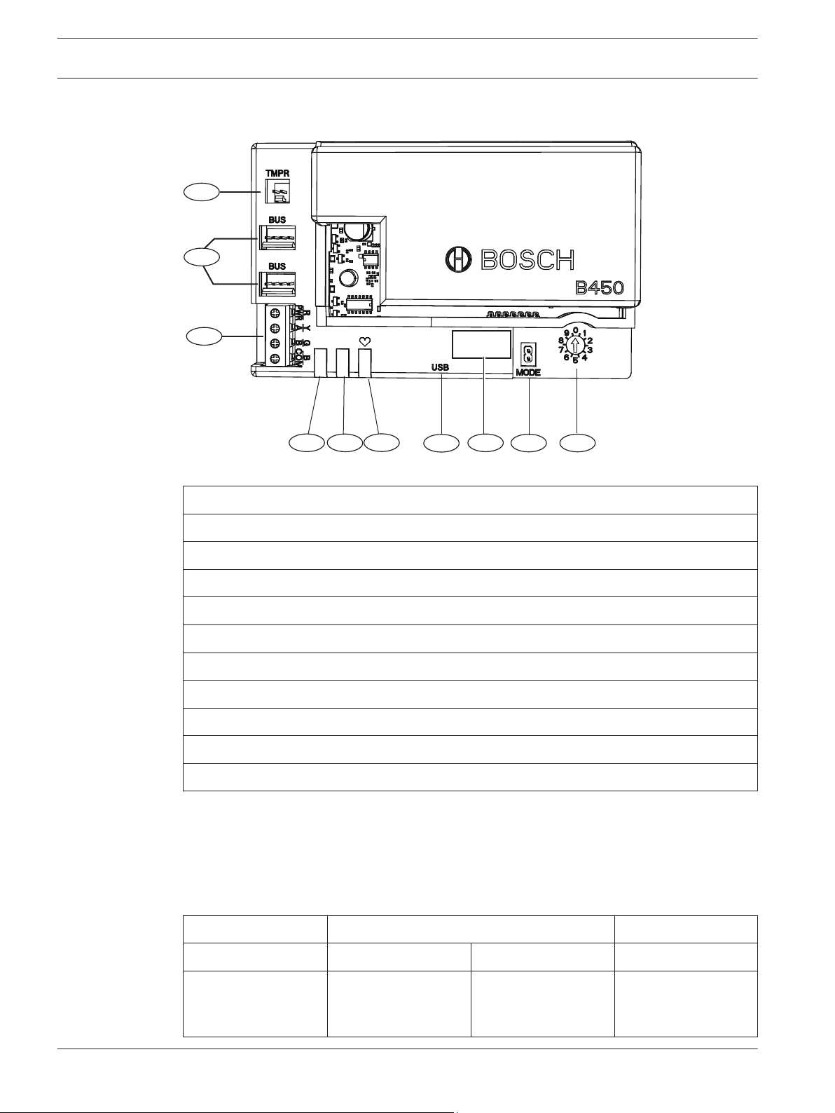
B450 module overview
Conettix Plug-in Communicator
Interface
Figure 3.1: B450 Plug-in Communicator Interface
Callout ᅳ Description
1 ᅳ Tamper switch connector
2 ᅳ Bus address switch
3 ᅳ MODE 2-pin jumper connector (for future use)
4 ᅳ Bus address label
5 ᅳ USB connector (Type A)
6 ᅳ Heartbeat LED
7 ᅳ RX LED (indicates packets received from the wireless network)
8 ᅳ TX LED (indicates packets transmitted over the wireless network)
9 ᅳ Terminal strip (to control panel)
10 ᅳ Interconnect wiring connectors (to control panel or other compatible modules)
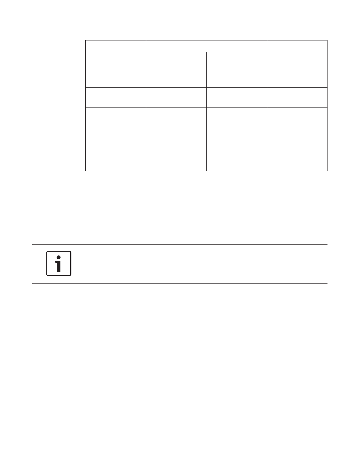
3.2
B450 cellular interface compatibility
The B450 supports multiple bus types. Use the following table to determine the supported
applications and features by bus type. the following table for supporting compatibility
applications.
Installed Bus
Function Option/SDI SDI2 Details
2014.12 | 06 | F.01U.300.740 Installation and Operation Guide Bosch Security Systems, Inc.
IP Event Reporting Y Y TCP communication
is only supported on
SDI2
Conettix Plug-in Communicator
Interface
Installed Bus
System overview | en 9
3.3
Remote Program
(RPS or A-link)
Y Y Requires Bosch
Cellular service or
other cellular network
access
Configure B450 from
control panel
Personal Notification
via SMS or Email
N Y GV4/B Series require
v2.03+
N Y Requires compatible
control panel and
cellular plan
Remote Security
Control App
N Y Requires Bosch
Cellular service or
other cellular network
access
Table 3.1: B450 cellular interface compatibility
Bus address settings overview
The address switch determines the bus address for the B450 Conettix Plug-in Communicator
Interface. The control panel uses the address for communications. Use a slotted screwdriver
to set the address switch.
Notice!
The B450 reads the bus address switch setting only during power up. If you change the
switch after you apply power to the module, you must cycle the power to the module in order
for the new bus address setting to be used for bus communication.
Bus address label
Use the bus address label to select the desired setting on the bus address switch, depending
on your control panel.
Bosch Security Systems, Inc. Installation and Operation Guide 2014.12 | 06 | F.01U.300.740

PANEL ADDRESSES
TX
RX
0 1 2 4 5 6 7 8 9
Bus cfg 1 2 88 92 250
Addr SDI2
SDI
Option
134
13
14
10 en | System overview
Conettix Plug-in Communicator
Interface
Figure 3.2: Bus address label
2014.12 | 06 | F.01U.300.740 Installation and Operation Guide Bosch Security Systems, Inc.
!
Conettix Plug-in Communicator
Interface
Installation | en 11
4
4.1
Control panels
Installation
Perform the following steps to install the B450.
Caution!
Remove all power (AC and battery) before making any connections. Failure to do so might
result in personal injury and/or equipment damage.
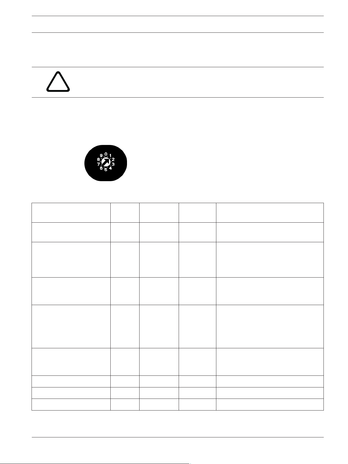
Setting the bus address
The B450 Conettix Plug-in Communicator Interface address switch provides the value for the
module's address. The figure below shows the address switch setting for address 1. Refer to
the table below for panel-specific settings.
Figure 4.1: Address switch set to address 1
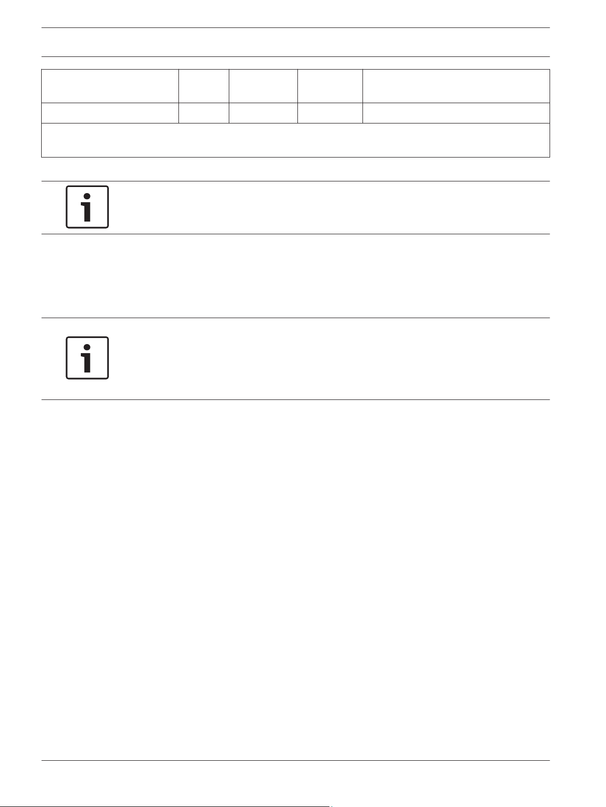
Switch
position
Control panel
bus address
Bus type Function
USB or SMS configuration
setting
B5512/B4512/
B3512,D9412GV4/
D7412GV4/D7212GV4
Solution 2000/3000
D9412GV4/D7412GV4/
D7212GV4
Solution 2000/3000
D9412GV4/D7412GV4/
D7212GV4, D9412GV3/
D7412GV3/D7212GV3,
D9412GV2/
D7412GV2/7212GV2 v7.06+
D9412GV4/D7412GV4/
D7212GV4, D9412GV3/
D7412GV3/D7212GV3
AMAX 2000/2100/3000/4000 6 134 Option Remote Programming or Reporting
CMS 6/8, CMS 40 6 134 Option Remote Programming or Reporting
0 N/A Any Change configuration
1 1 SDI2 Automation, Remote Programming, or
Reporting
2 2 SDI2 Automation, Remote Programming, or
Reporting
4 88 SDI
5 92 SDI
1
1
Remote Programming or Reporting
Remote Programming or Reporting
Easy Series v3+ 6 134 Option Remote Programming or Reporting
Bosch Security Systems, Inc. Installation and Operation Guide 2014.12 | 06 | F.01U.300.740
12 en | Installation
Conettix Plug-in Communicator
Interface
Control panels Switch
position
Control panel
bus address
Bus type Function
FPD-7024 9 250 Option Remote Programming or Reporting
1
For D9412GV4/D7412GV4/D7212GV4 configurations, SDI2 bus connection is the recommended configuration
option, but SDI bus configuration is also supported.
Table 4.1: B450 address switch settings
Notice!
Address switches 3, 7, and 8 are not supported on the B450.
4.2
Insert the communication module
Insert the desired B44x communication module into the slot of the B450 until you feel the
module “click” into place.
Notice!
Review your communication module prior to insertion into the B450. Depending on the
physical attributes of your communication module, insert your module accordingly using the
supported installation process (Section 4.2.1 without a SIM card, or Section 4.2.2 with a SIM
card).
2014.12 | 06 | F.01U.300.740 Installation and Operation Guide Bosch Security Systems, Inc.
Conettix Plug-in Communicator
Interface
Installation | en 13
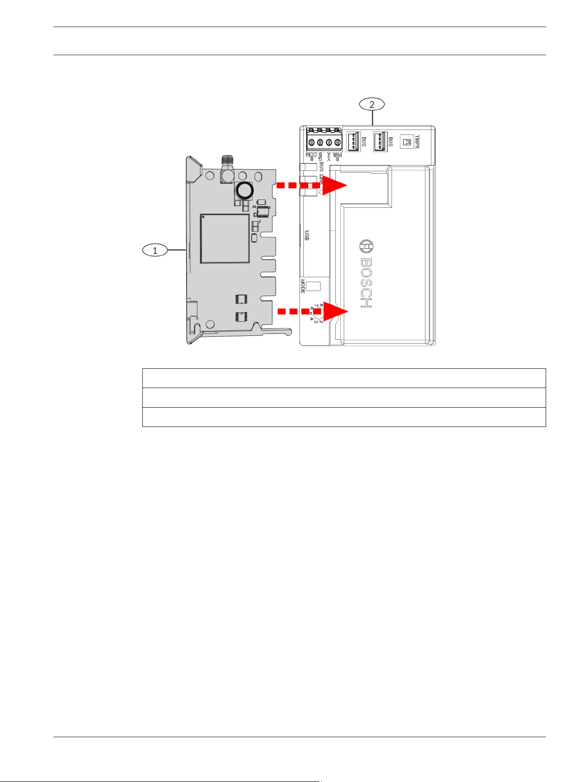
4.2.1
Insert the B44x communication module (required and available separately)
Figure 4.2: Inserting the communication module into the B450
4.2.2
Callout ᅳ Description
1 ᅳ B44x Plug-in Communicator module (available separately)
2 ᅳ B450 Conettix Plug-in Communicator Interface
Insert the B44x communication module with SIM card (required and available separately)
Insert the desired B44x communication module with supporting SIM card into the slot of the
B450 until you feel the module “click” into place.
Bosch Security Systems, Inc. Installation and Operation Guide 2014.12 | 06 | F.01U.300.740

2
3
1
14 en | Installation
Conettix Plug-in Communicator
Interface
4.3
Figure 4.3: Inserting the communication module with supporting SIM card into the B450
Callout ᅳ Description
1 ᅳ B44x Plug-in Communicator SIM card insertion (required and, available separately)
2 ᅳ B44x Plug-in Communicator module (available separately)
3 ᅳ B450 Conettix Plug-in Communicator Interface
Mount the module in the enclosure
Notice!
If you are not using the interconnect cable, it is recommended to wire the B450 module to
the compatible control panel via the terminal strip prior to mounting the B450 into the
enclosure. Failure to do so will complicate the mounting procedure.
Mount the B450 Conettix Plug-in Communicator Interface using the interior wall of the
enclosure’s 3-hole mounting pattern and the supplied mounting screws.
Notice!
UL requirement
Mount the module in the control panel enclosure, or in a UL listed enclosure. For Commercial
Burglary applications, house all communicators in tampered enclosures.
All communicators shall be housed in tampered enclosures. If the unit is used in a commercial
burglar environment, and is enclosed in a commercial enclosure, that enclosure must be
tampered.
If the installation is a local or police station connection, then the B450 must be mounted
inside an attack resistant enclosure.
2014.12 | 06 | F.01U.300.740 Installation and Operation Guide Bosch Security Systems, Inc.

Conettix Plug-in Communicator
Interface
Figure 4.4: Mounting the module to the exterior wall of the enclosure
Installation | en 15
4.3.1
Callout ᅳ Description
1 ᅳ B450
2 ᅳ Enclosure (outside wall shown)
3 ᅳ Mounting screws (3 screws included)
Installing in a control panel enclosure
Install the B450 on the inside enclosure wall that also contains the supported control panel.
The control panel powers the B450 via the terminal block or bus connection.
Installing in a separate enclosure
Install the B450 on the inside wall of a separate enclosure. The control panel in a nearby,
separate enclosure powers the B450 via the terminal block or bus connection.
Installing in a separate enclosure with separate power supply
Install the B450 on the inside wall of a separate enclosure that also has a separate external
power supply such as the B520 Auxiliary Power Supply Module.
Mount and wire the tamper switch (option for SDI2 bus only)
When the tamper input is shorted, the firmware version flashes, then the B450 LEDs are
disabled to conserve power. To see the troubleshooting LEDs, open the tamper circuit or
jumper.
You can connect an enclosure door tamper switch for one module in an enclosure.
Installing the optional tamper switch for use with a B450:
1. Mount the tamper switch into the enclosure’s tamper switch mounting location.
2. Plug the tamper switch wire onto the module’s tamper switch connector. For the tamper
switch connector location, refer to Module overview, page 7.
3. Verify the B450 module is configured with tamper enabled ON within the SDI2 supported
control panel.
Bosch Security Systems, Inc. Installation and Operation Guide 2014.12 | 06 | F.01U.300.740
1
2
16 en | Installation
Conettix Plug-in Communicator
Interface
4.4
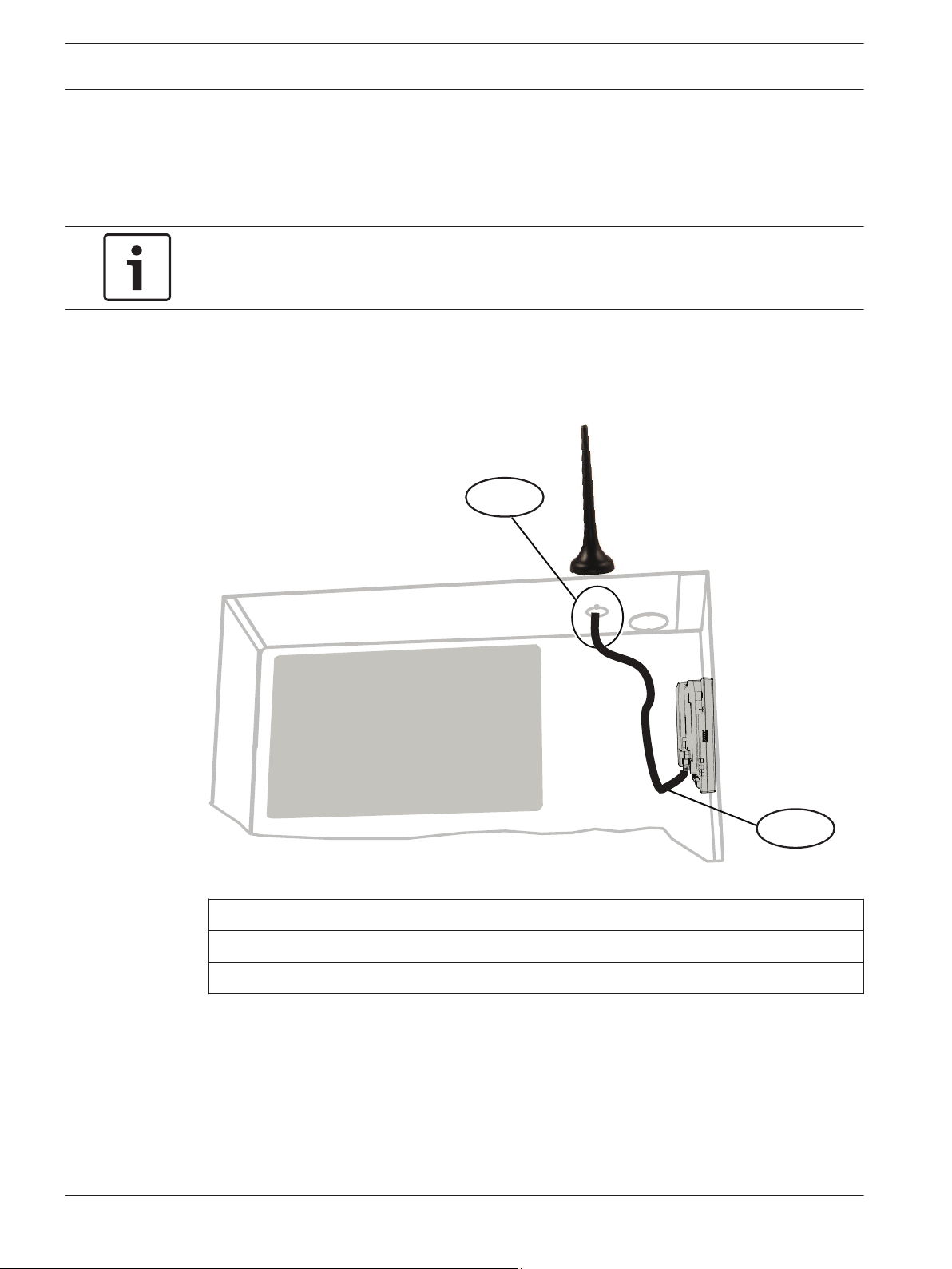
Install and mount the plug-in communicator antenna
Installing and mounting the magnetic antenna:
1. Place the magnetic antenna on top of the enclosure, or vertically on another metal
surface.
Notice!
If you are experiencing a weak signal, place the antenna on top of a metal surface that has a
radius of 10.16 cm (4 in) for optimal performance.
2. Route the antenna cable through a knock-out in the enclosure wall.
3. Connect the antenna cable to the module.
4. Secure the antenna cable to the inside of the enclosure.
5. Secure the extra antenna cable length inside the enclosure.
Figure 4.5: Antenna installation
Callout ᅳ Description
1 ᅳ B44x plug-in cellular communicator antenna (routed through any knock-out)
2 ᅳ B44x plug-in cellular communicator antenna cable (connected to the module)
4.5
2014.12 | 06 | F.01U.300.740 Installation and Operation Guide Bosch Security Systems, Inc.
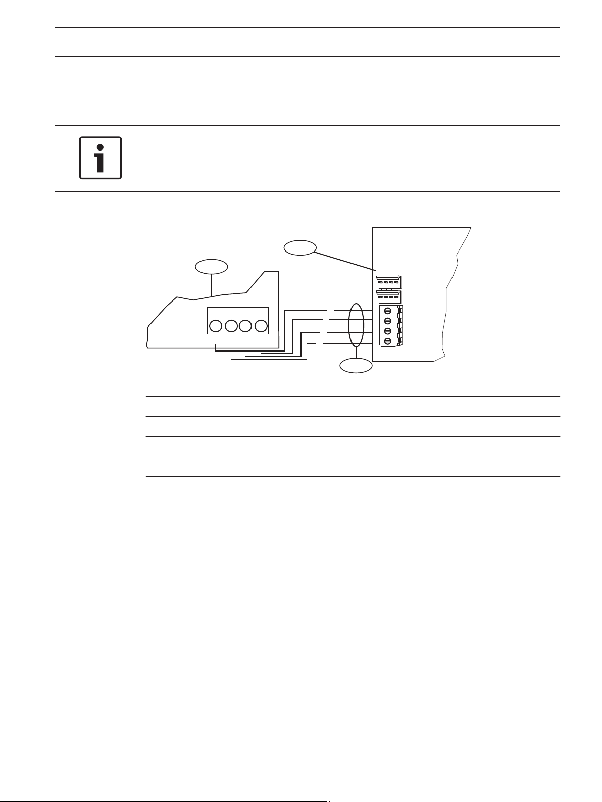
Wire to the control panel
When you wire a module to an SDI, or SDI2 control panel, you can use either the module's
terminal strip labeled R, Y, G, B (PWR, A, B, COM) or the module's interconnect wiring
connectors (wire included). The figure below indicates the location of both the terminal strip
and the interconnect wiring connectors on the module.
R
Y
G
B
R
Y
G
B
3.7 - 5.0 VDC
2.0 - 3.0 VDC
0.0 - 1.3 VDC
Open
Normal
Short
3
R
Y
G
B
1
1
2
4
2
7 COM 8
C
OUTPUT
B
1 k End of Line Resistors
Voltage Ranges
ON-BOARD POINTS
3 COM 4 5 COM 61 COM 2
R Y G B
SDI2
Device Bus
AUX
- 12 V +
7 COM 8
C
OUTPUT
B
1 k End of Line Resistors
Voltage Ranges
ON-BOARD POINTS
3.7 - 5.0 VDC
2.0 - 3.0 VDC
0.0 - 1.3 VDC
Open
Normal
Short
3 COM 4 5 COM 61 COM 2
R Y G B
SDI2
Device Bus
AUX
- 12 V +
TMPR
1 COM 2 7 COM 83 COM 4 5 COM 6
RESET
COM AUX R Y G B
PWR A B COM
B C
OUTPUT
TMPR
1 COM 2 7 COM 83 COM 4 5 COM 6
RESET
COM AUX R Y G B
PWR A B COM
B C
OUTPUT
Conettix Plug-in Communicator
Interface
Notice!
Use either the terminal strip wiring or interconnect cable to wire to the control panel. Do not
use both. When connecting multiple modules, you can combine terminal strip and
interconnect wiring connectors to daisy-chain the modules in series.
Installation | en 17
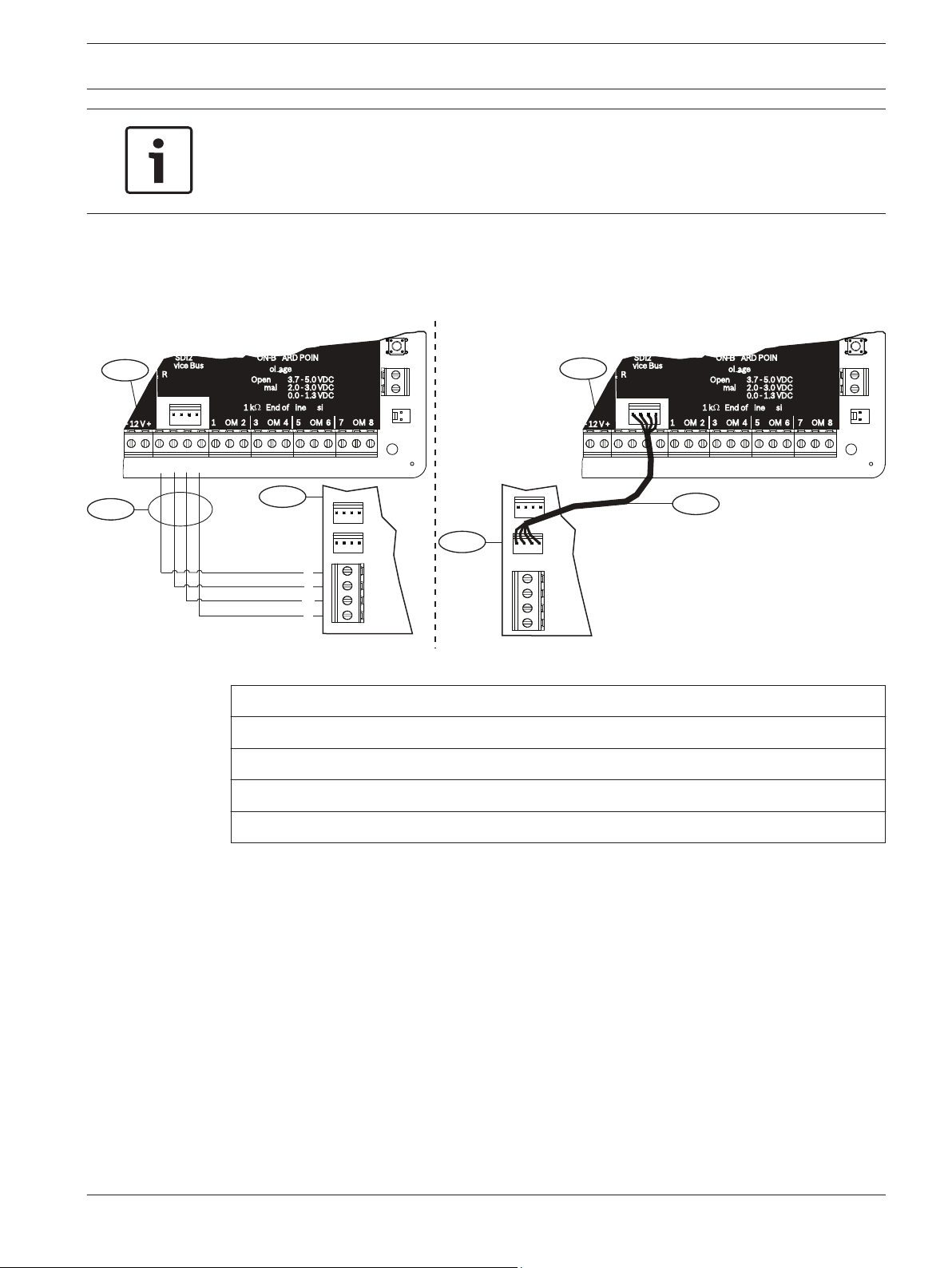
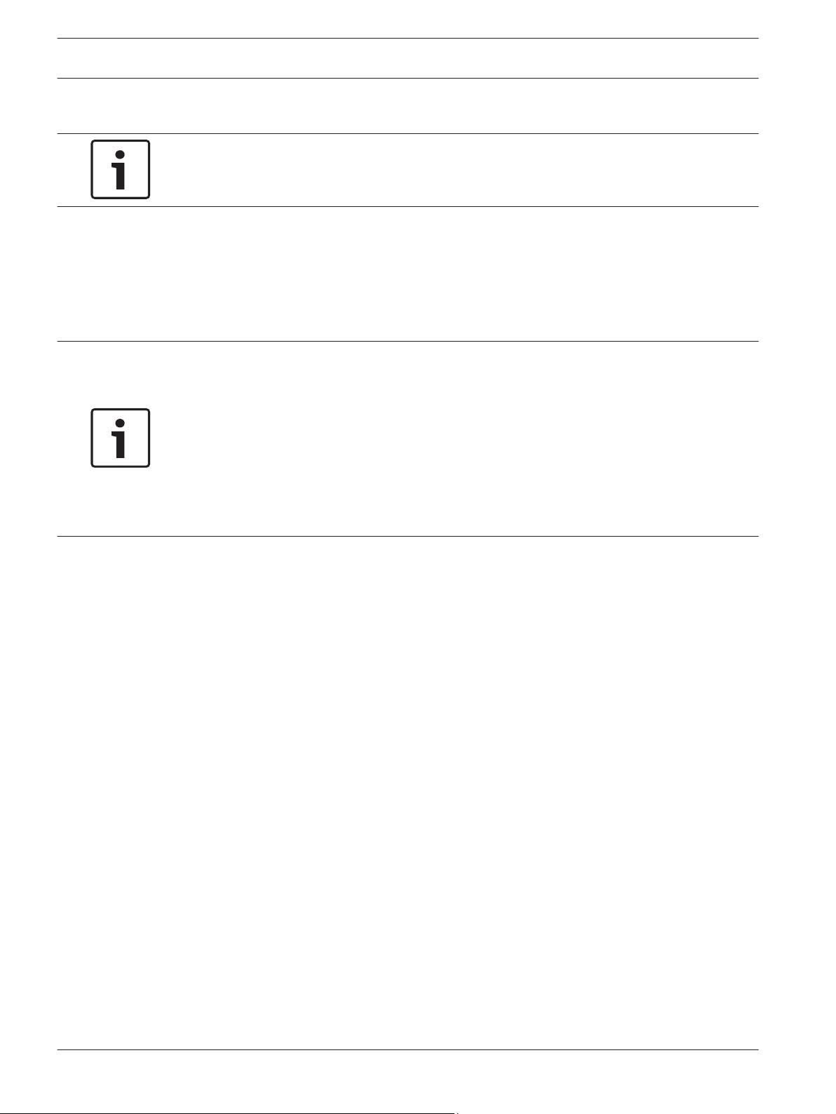
4.5.1
Wire to an SDI2 control panel
Run the wiring connections from the module to the data bus terminals on the compatible
control panel.
Figure 4.6: Using terminal strip or interconnect cable wiring on an SDI2 control panel (B Series control panel shown)
Callout ᅳ Description
1 ᅳ Compatible SDI2 control panel (B Series control panel shown)
2 ᅳ B450
3 ᅳ Terminal strip wiring
4 ᅳ Interconnect cable
Bosch Security Systems, Inc. Installation and Operation Guide 2014.12 | 06 | F.01U.300.740
R
Y
G
B
R
Y
G
B
3
R
Y
G
B
1
1
2
4
2
Commercial Protected-Premises Control Panel
D9412GV3 Control Panel is UL Listed For Central Station, Remote Station, Local, Auxiliary,
Proprietary, and Household Fire Alarm, and Central Station, Local, Proprietary,
Police Station Connect, Household Burglar Alarm
and Encrypted Line Security when
communicating via a network.
System is intended to be checked by a Qualified Technician at least every 3 years.
The types of initiating circuits the control panel has been approved for are A, M, W, SS.
The types of signaling the control panel has been approved for are DAC, OT, NC, RevPol.
VOLTAGE RANGES
Open 3.7 - 5.0 VDC Short 0.0 - 1.3 VDC
Normal 2.0 - 3.0 VDC
Reset Pin
Disable all except Battery
Charging and Programming
PERIPHERAL DEVICE CONNECTIONS
RED
POWER +
YELLOW
DATA BUS A
GREEN
DATA BUS B
BLACK
COMMON
ZONEX OUT 1
ZONEX IN 1
NFPA
Style 4.0
Signaling
Line
Circuits
This equipment should be installed in accordance with the NFPA 70 (National Electrical Code) and
NFPA 72 (National Fire Alarm Code).
D9412GV3
26
25
ZONEX POWER +
24
ZONEX COMMON
23
SDI Connector
ZONEX OUT 2
ZONEX IN 2
Refer to the D9412GV3/D7412GV3 Approved Applications Compliance Guide (P/N: F01U143069)
for System Wiring Diagram, Issue A and for compatible smoke detectors. 2-wire Compatible Identifier “A”.
POWER SUPPLY REQUIREMENTS
The Power Supply provides a maximum of 1.4 Amps for the Control Panel and all
Accessory Devices. For System Loading, refer to the D9412GV3/D7412GV3 Operation
and Installation Guide (P/N: F01U143070).
(P/N: F01U143070) for Power Requirements relating to Terminals 6 and 7 .
All external connections except Terminal 5 (battery positive) are inherently power
limited. Requirements for battery standby time might reduce allowable output.
Battery: Replace every 3 to
5 years with one or two Model
D126 or D1218 12 V Lead Acid
Batteries.
Operation Monitor LED
Pulses when Normal
Flickers when Ringing
GREEN
Point 8, S3 Option
Closed = 1 kΩ EOL
Normal Operation
Open =AB-12 UL
Bell Box 220 kΩ
25
Point 3
Point 4
1614
Point 1
Point 2
11 13
Point 5
Point 6
17 19
Point 7
Point 8
21
20
22
Minimum system requirements for Classification in accordance with ANSI/SIA CP-01-2007:
UL Listed and Classified control unit Model D9412GV3, D7412GV3, or D7212GV3;
UL Listed and Classified keypad Model D1256, D1257, D1260, D1255, D1255R, or D1255RW;
UL Listed Local Bell
WARNING!
To prevent risk of
electric shock,
disconnect AC
power and
telephone lines
before servicing.
181512
Not suitable for remote station protected premises services where separate transmission circuits
are required for fire, supervisory (when applicable) and trouble signals when using D185.
18 en | Installation
Conettix Plug-in Communicator
Interface
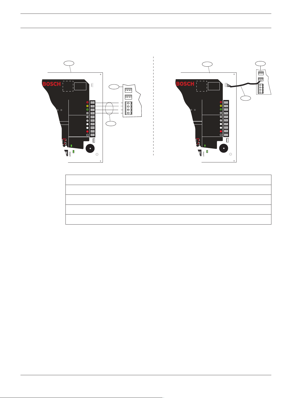
4.5.2
Wire to an SDI control panel
Figure 4.7: Using terminal strip or interconnect cable wiring on an SDI control panel (GV3 Series control panel shown)
Callout ᅳ Description
2014.12 | 06 | F.01U.300.740 Installation and Operation Guide Bosch Security Systems, Inc.
1 ᅳ Compatible SDI control panel (GV3 Series control panel shown)
2 ᅳ B450
3 ᅳ Terminal strip wiring
4 ᅳ Interconnect cable
R
Y
G
B
R YGB
2
1
3
R
Y
G
B
Conettix Plug-in Communicator
Interface
Installation | en 19
4.5.3
Wire to an option bus control panel
Run the wiring connections from the module to the data bus terminals on the compatible
control panel.
Notice!
When wiring the connections between the option bus terminal strip and the B450, verify the
terminal position of the colored wires as they may be in a different orientation (option bus =
R, B, G, and Y) and (B450 = R, Y, G, and B).
Figure 4.8: Wiring to an option bus terminal strip (
Callout ᅳ Description
1 ᅳ Compatible control panel (FPD-7024 control panel shown)
2 ᅳ B450
3 ᅳ Terminal strip wiring
For complete wiring instructions, refer to the control panel documentation.
Bosch Security Systems, Inc. Installation and Operation Guide 2014.12 | 06 | F.01U.300.740
20 en | Configuration
Conettix Plug-in Communicator
Interface
5
5.1
Configuration
Notice!
Power up the system prior to the configuration workflows described in this chapter.
You can configure the B450 using one of the methods described in this section for your
control panel type.
Configuration for SDI2 control panels
Perform the following to configure the B450 to supporting SDI2 control panels.
Notice!
By default, when connecting a field replacement B450 to an existing SDI2 control panel, the
control panel overrides some of the module settings such as; TCP/UDP Port Number, AES
Encryption, Tamper, Panel Programming, IPv4 DNS Server IP Address, Alternate IPv4 DNS
Server IP Address, and TCP Keep Alive Time. To keep custom module settings when you
connect a module to a configured control panel, you must disable Panel Programming prior to
connecting to the SDI2 bus. This is accomplished by using either USB, or SMS configuration.
If the SDI2 control panel is not defaulted, the control panel sends the network configuration
parameters to the B450.
Address-only configuration conditions
An SDI2 control panel automatically configures a newly connected module.
1. If the control panel is not at factory default, it transfers the configuration settings in the
control panel to the B450.
2. Verify that the address switch is set to the correct address for the control panel (SDI2
control panels use address 1 or 2). If the switch is not set to the correct address, power
down the system, set the correct address, and then power up the system.
3. Program the control panel communication settings using RPS or the keypad.
The control panel stores the module settings and automatically programs a defaulted module
when connected. If manual module programming is required, use USB or SMS configuration to
set the Panel Programming parameter to Disabled before installing.
5.1.1
2014.12 | 06 | F.01U.300.740 Installation and Operation Guide Bosch Security Systems, Inc.
Configuring and viewing status from RPS
Configuration
For SDI2 control panels, the networking related parameters in the Networking parameters in
RPS table can be configured through the panel or RPS. When cellular specific parameters need
to be modified, refer to the USB or SMS configuration sections within this installation and
operation guide for programming workflows and operation.
The B450 parameters within RPS can be found under the SDI2 Modules section. Refer to the
chart below for RPS selections:
Loading...