


INSTALLATION INSTRUCTIONS
INSTRUCTIONS D'INSTALLATION
INSTRUCCIONES DE INSTALACIÓN
Bottom Freezer (2$door)
Congélateur inférieur (2$portes)
Congelador independiente (2$puertas)
2

Contents
Before you Begin. . . . . |
. . . . . |
. . |
. . . . |
. . . |
. |
. |
.. .. |
.. .. .. |
.. .. |
.. |
.. .. .. .. .. .. .. .. .. .5. .. .. .. .. |
Definitions . . . . . . . |
. . . . . |
. . . . . . . . . . . . . . . . . . . . . . . . . . . . . . 5. . . . . |
|||||||||
Important information. . . |
. . . . . |
. . |
. . . . |
. . . |
. |
. |
. . . |
. .. |
.. .. .. |
.. |
.. .. .. .. .. .. .. .. .. ..5 .. .. .. .. |
Installation options. . . . . . . . . . . . . . . . . . . . . . . . . . . . . . . . . . . . . . . . . . . . . . . . . . . . . . .6. . . . . . . . |
|||||||||||
Individual unit. . . . . . |
. . . . . |
. . |
. . . . . |
. . |
. . |
. . . . . . . . . . . . . . . . . . . . . . . . . . . . . . . . . . . . . .6. . . . . . . . |
|||||
Side by Side . . . . . . |
. . . . . |
. . |
. . . . . |
. . |
. . |
. . . . . . . . . . . . . . . . . . . . . . . . . . . . . . . . . . . . . .6. . . . . . . . |
|||||
Individual appliances with |
partition. . |
. . |
. . . . . |
. . |
. . |
. |
. . |
. . . |
. . |
. |
. . . . . . . . . . . . . . . . . . . .6. . . . . . . . . |
At the end of the kitchen . units. . . . . . . . . . . . . . . . . . . . . . . . . . . . . . . . . 6. . . . .
Installation location. . . . . . . . . |
. . . . . |
. . . |
. . . |
. |
. |
. |
. . . . . . |
. . . . . . . . .7 . . . . |
|||||||
Installation |
room . . . . . . . . . . |
. . . . . . . . . . . . . . . . . . . . . |
. . . . . . . . .7 . . . . |
||||||||||||
Installation |
cavity. . . . . . . . . . |
. . . . . |
. . . |
. . . |
. |
. . . . . . . . . . . . . . . . . . . . . . . . . . . . . . . . . .7. . . . . . . . . |
|||||||||
Furniture/fixtures . . . . . . . . . . |
. . . . . |
. . . |
. . . |
. . . . . . . . . . . . . . . . . . . . . . . . . . . . . . . . . . . .7. . . . . . . . . |
|||||||||||
Base . . . . . . . . . . . . . . . |
. . . . . |
. . . . . . . . . . . . . . . . . . . . . . . . . . . . . . . . . . . . . . . . . . . . . . .7. . . . . |
|||||||||||||
Connecting the power. . . . . . . . . . . . . . . . . . . . . . . . . . . . . . . . . . . . . . . . . . . . . . . . . . . .8. . . . . . . . . |
|||||||||||||||
Additional grounding procedure. . . . . . . . . . . . . . . . . . . . . . . . . . . . . . . . . . . . . . . . . . . .8. . . . . . . . . |
|||||||||||||||
Grounding |
instruction. . . . . . . . |
. . . . . |
. . . |
. . . |
. |
. . |
. . . . . . . . . . . . . . . . . . . . . . . . . . . . . . .8. . . . . . . . . |
||||||||
Connecting the water. . . . . . . . . . . . . . . . . . . . . . . . . . . . . . . . . . . . . . . . . . . . . . . . . . . . .8. . . . . . . . . |
|||||||||||||||
Installation dimensions. . . . . . . . |
. . . . . |
. . . |
. . . |
. . . . . . . . . . . . . . . . . . . . . . . . . . . . . . . . .9. . . . . . . . . |
|||||||||||
Single |
installation. . . . . . . . . . |
. . . . . |
. . . |
. . . |
. . . . . . . . . . . . . . . . . . . . . . . . . . . . . . . . . . . .9. . . . . . . . . |
||||||||||
Side by Side |
installation. . . . . . . |
. . . . . |
. . . |
. . . |
. |
. . |
. |
. . . . . . . . . . . . . . . . . . . . . . . . . . .10. . . . . . . . . . |
|||||||
Appliance dimensions. . . . . . . . |
. . . . . |
. . . |
. . . |
. |
. . . . . . . . . . . . . . . . . . . . . . . . . . . . . . .11. . . . . . . . . |
||||||||||
Required |
accessories |
and tools. . . . |
. . . . . |
. . . |
. . . |
. |
. |
. |
. . . . . . |
. . . . |
. . . |
.12. . . . . |
|||
1. |
Supplied |
accessories. . . . . . . |
. . . . . |
. . . |
. . . |
. |
. |
. |
. . . . . . . . . . . . . . . . . . . . . . . . . . . .12. . . . . . . . . . |
||||||
2. |
Optional |
accessories. . . . . . . |
. . . . . |
. . . |
. . . |
. |
. |
. |
. . .. .. .. .. |
.. .. .. .. .. |
.. .. .. |
..12.. .. .. .. . |
|||
3. |
Other |
required |
accessories from |
specialist |
outlets. . . |
. . . |
. |
. |
. |
. . . . . . |
. . . . . |
. . . |
.12. . . . . |
||
4.Tools . . . . . . . . . . . . . . . . . . . . . . . . . . . . . . . . . . . . . . . . . . 12. . . . .
5.Other . . . . . . . . . . . . . . . . . . . . . . . . . . . . . . . . . . . . . . . . . . 12. . . . .
Installation instructions. . . . . . . . . . . |
. . . . . . . |
. . . |
.. .. |
.. .. |
.. |
.. .. |
.. .. |
.. |
.. .. .. .. ..13.. .. .. .. . |
||
1. |
Checking the installation cavity. . . . . . |
. . . . . . . |
. . . . . . . . . . . . . . . . . . 13. . . . . |
||||||||
2.. |
Transport of the appliance. . . . . . . . |
. . . . . . . |
. . . . . . . . . . . . . . . . . . 13. . . . . |
||||||||
3. |
Removing the packaging. . . . . . . . |
. . . . . . . |
. . . |
. . |
. . |
. . . . . . . . . . . . . . . . . . . . . .13. . . . . . . . |
. . |
||||
4. |
Preparing the appliance. . . . . . . . . |
. . . . . . . |
. . . |
. . |
. . . . . . . . . . . . . . . . . . . . . . . . . .14. . . . . . . . |
. . |
|||||
5. |
Changing over the door hinges. . . . . . |
. . . . . . . |
. . . |
. . |
. . |
. |
. . . . . . . . . . . . . . . . . . .14. . . . . . . . |
. |
|||
6. |
Preparing the installation cavity. . . . . . |
. . . . . . . |
. . . |
. . |
. . |
. |
. . |
. . . . . . . . . . . . . . . .16. . . . . . . |
. |
||
7. |
Attaching an alternative anti tip device. . . |
. . . . . . . |
. . . |
. . |
. . |
. |
. . |
. . |
. |
. . . . . . . . . .18. . . . . |
|
8. |
Preparing to connect the water. . . . . . |
. . . . . . . |
. . . |
. . |
. . |
. |
. . . . . . . . . . . . . . . . . . .18. . . . . . . . . |
|
|||
9. |
Attaching the edge protection. . . . . . |
. . . . . . . |
. . . |
. . |
. . . . . . . . . . . . . .19. . . . . |
||||||
3
10.Side by Side installation. . . . . . . . . . . . . . . . . . . . . . . . . . . . . . . . . . .19. . . . .
11. |
Pushing the appliance into the installation .cavity. . . . . . . . . . . . . . . . . . . . . . . 19. . . . . |
||||||||||
12. |
Installing and aligning the appliance. . . . . . . . . . . . . . . . . . . . . . . .. .. .. .. .. .. 20.. .. . . . |
||||||||||
13. |
Attaching the appliance to the top of the. .cavity. . . . . . . . . . . . . . . . . . . . . . .21. . . . . |
||||||||||
14. |
Attaching the individual appliance to the side of the. .cavity. . . . . . . . . . . . . . . . . . 22. . . . . |
||||||||||
15. |
Connecting the water to the appliance. . . . . . . . . . . . . . . . . |
. |
. . |
. . |
. . . . . . . . . . . .22. . . . . . |
||||||
16. |
Attaching the toe kick panel. . . . . . . . . . . . . . . . . . . . . |
. |
. .. .. |
.. .. |
.. .. .. .. .. |
..23.. .. .. .. . |
|||||
17. |
Commissioning the Appliance. . . . . . . . . . . . . . . . . . . . |
. |
. . .. |
.. .. |
.. .. .. .. .. |
..24.. .. .. .. . |
|||||
18. |
Preparing the furniture doors. . . . . . . . . . . . . . . . . . . . . . . .. .. .. .. .. .. .. .. .. 24.. .. .. .. .. |
||||||||||
19. |
Loading the appliance door. . . . . . . . . . . . . . . . . . . . . |
. |
. . . . . . . . . . . . . . . . . . . .25. . . . . . . . . . |
||||||||
20. |
Attaching the adjusting rail to the furniture door (refrigerator compartment). . . . . |
. . |
. . . . . |
. . . . . 25. |
|||||||
21. |
Attaching |
and |
aligning |
the furniture |
door |
(refrigerator compartment). . . . . |
. . . . . . . . . . . . . .26. . |
||||
22. |
Attaching the adjusting rail (freezer compartment). . . . . . . . . . . . . . . . . . . . . . . .27. . . . . |
||||||||||
23. |
Attaching |
and |
aligning |
the furniture |
door |
(freezer compartment). . . . . . |
. . . . . . . . . . . .28. . . . . |
||||
24. |
Attaching the furniture door (refrigerator compartment). . . . . . . . . . . . . . . . . . . . . 29. . . . . |
||||||||||
25. |
Attaching the furniture door (freezer compartment). . . . . . . . . . . . . . . . . . . . . . . 30. . . . . |
||||||||||
26. |
Attaching the lower bracket. . . . . . . . . . . . . . . . . . . . . |
. . . . . . . . . . . . . . . . . . . . . .31. . . . . . . . . . |
|||||||||
27. |
Attaching the finger guard. . . . . . . . . . . . . . . . . . . . . . |
. . . . . . . . . . . .31. . . . . |
|||||||||
28. |
Attaching the covers. . . . . . . . . . . . . . . . . . . . . . . .. |
.. |
.. .. .. |
.. .. .. .. .. .. .. ..32.. .. .. .. . |
|||||||
29. |
Mounting of air separator. . . . . . . . . . . . . . . . . . . . . . |
. . . . . . . . . . . . . . . . . . . . . . .33. . . . . . . . . . |
|||||||||
30. |
Adjusting the door opening angle. . . . . . . . . . . . . . . . . . . . . . . .. .. .. .. .. .. .. 34.. .. .. . . |
||||||||||
31. |
Changing |
the |
door spring. . . . . . . . . . . . . . . . . . . . . . |
. . . . . . . . . . . . . . . . . . . . . . .34. . . . . . . . . . |
|||||||
4

Before you Begin
Read these instructions completely and carefully.
e |
IMPORTANT |
|
|
|
|
These installation instructions are intended for use by |
||||||||||||
Save |
these |
instructions |
for local |
inspector's |
use. |
qualified installers. All connections for water, electrical |
||||||||||||
power and |
grounding must comply with local codes a |
|||||||||||||||||
Observe all |
governing |
codes |
and |
ordinances. |
|
|||||||||||||
|
ordinances |
and |
be |
made |
by |
licensed personnel when |
||||||||||||
|
|
|
|
|
|
|
|
|||||||||||
Note to Installer?Be sure |
to |
leave these instructions required. In |
the |
absence |
of |
a |
local |
code: |
||||||||||
with |
the Consumer. |
|
|
|
|
|
- |
In theU.S.A., |
in |
accordance |
with |
the |
National |
|||||
|
|
|
|
|
|
|
|
|||||||||||
Note to Consumer? Keep |
these |
instructions |
with your |
Electric |
Code, |
ANSI/NFPA70 |
- latest |
edition/State |
||||||||||
Owner's Manual for future |
reference. |
|
|
and Municipal |
codes |
and/or |
local |
codes. |
||||||||||
- In Canada, in accordance with the Canadian Electric Code C22.1 - latest edition/Provincial and Municipal codes and/or local codes.
Definitions
These appliances are top heavy and must be d secured to prevent the possibility of tipping forward. Anti tip protection is required.
Keep doors closed until the appliance is completely installed and secured per installation instructions.
Due to the weight and size of this appliance, and tod reduce the risk of personal injury or damage to the product ?TWO PEOPLEARE REQUIRED FOR
PROPER INSTALLATION.
WARNING d
CAUTION |
d |
|
|
|
|
||
|
minor or moderate |
|
|
|
a result of not |
|
|
|
|
|
|
e |
CAUTION |
|
|
|
|
This symbol |
is used to draw |
the |
user's attention |
|||||
|
|
i |
|
|||||||||||
Skill - Level ? Installation of this appliance requires basicsomething in particular. |
|
|
|
|||||||||||
mechanical, carpentry and plumbing skills. Proper |
|
|
|
|
|
information |
|
|
|
|||||
installation is the responsibility of the installer. ProductImportant |
|
|
|
|||||||||||
failure due to improper installation is not covered |
under |
importance |
of complying with |
all |
regulations |
|||||||||
|
|
|
|
|
|
The |
||||||||
the Appliance Warranty. See the Owner's Manual |
for and instructions |
in this installation manual cannot be |
||||||||||||
warranty |
information. |
|
|
emphasised enough. |
The installation should be carried |
|||||||||
|
WARNING |
|
|
out by a qualified fitter. |
|
|
|
|||||||
e |
|
|
Before starting the installation, always read this |
|||||||||||
Use |
this |
appliance |
only for |
its intended purpose. |
|
installation manual in full. It contains important details |
||||||||
Immediately repair |
or replace |
electric service cords |
|
which |
the fitter |
must |
observe. |
Provided this manual is |
||||||
that |
|
thoroughly, |
the |
installation |
will |
be |
simple, |
|||||||
become |
frayed or |
damaged. |
|
|
read |
|||||||||
|
|
trouble free and, most importantly, |
safe. |
|||||||||||
|
|
|
|
|
|
|||||||||
Unplug the appliance or switch off the fuse before cleaning or making repairs.
Repairs should be made by a qualified service technician.
5
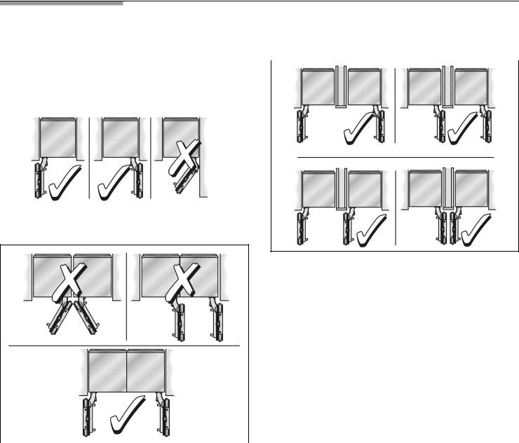
Installation |
options |
|
finger Individual appliances with partition |
|||||
design of the |
kitchen |
and the |
function of |
the |
||||
The different |
installation |
options |
are limited |
only |
|
by the |
||
guard. |
|
|
|
|
|
|
|
|
|
|
|
|
|
|
|
|
|
Individual |
unit |
|
|
|
|
|
|
|
|
|
|
|
|
|
|
|
|
|
|
|
|
|
|
|
|
|
Side$by$Side
i |
Note |
|
|
|
- |
When dimensioning the partition |
for model 4, |
note |
|
|
the thickness of the furniture fronts to prevent |
|||
|
damage if the doors |
are opened at the same tim |
||
- |
Use theExtreme Combination Side$by$Side |
|
||
|
Heating kitf the gap |
between |
the appliances |
is |
|
less than 6" (160mm). |
|
|
|
|
See the section on •Optional accessories" on |
|
||
|
page 12. |
|
|
|
- |
Minimum thickness of |
5 |
|
|
the partition/ " (16mm). |
|
|||
|
|
|
8 |
|
|
At |
the |
end |
of the |
kitchen |
units |
|
|
If one side |
of the |
appliance |
is visible, a |
side panel |
||
* Partition required! |
|||||||
be |
used. |
|
|
|
|
||
i |
When |
2 |
appliances are installed Side by Side, |
|
the Basic |
Combination Side$by$Side Sealing |
|
|
must |
be |
used to ensure a stable connection. |
See the section on •Optional accessories" on page 12.
|
The side |
panel must |
be connected firmly to the wall, |
|
kit |
the floor |
and |
overhead |
furniture/fixtures before the |
|
appliance |
is |
placed in |
the cavity. |
The dimensions of the side panel are taken from the opposite cavity wall. During installation ensure that the cavity is square and the exact size.
6

Installation location
d |
|
WARNING |
d |
|||
|
|
|
|
|
|
|
Do |
not |
install |
the |
appliance: |
|
|
- |
outdoors, |
|
|
|
|
|
- |
in an |
environment with dripping water, |
|
|
||
- in rooms which are at risk of frost. |
|
|
||||
Appliance is very heavy ? for empty weight see |
|
|||||
following |
table: |
|
|
|
|
|
Bottom |
Freezer |
36" |
approx. 430 lbs |
/ 195 |
|
|
|
|
|
|
|
|
|
|
i |
|
The side |
walls of |
the |
cavity must |
be |
flush. |
||
|
The |
minimum |
thickness |
of |
side |
walls |
and |
the |
top wa |
|
|
|
|
5 |
|
|
|
|
|
|
|
|
must be /8" (16mm). |
|
|
|
|
|
|
|||
|
The |
minimum |
thickness |
of |
toe |
kick panel |
must |
be |
||
|
1/ " (13 mm). |
|
|
|
|
|
|
|
||
2 |
|
3 |
|
|
|
|
|
|
||
|
|
|
|
|
|
|
|
|
||
|
A thickness of/4" (19mm) is recommended. |
|
|
|||||||
the |
|
|
|
|
|
|
|
|
||
|
Furniture/fixtures |
|
|
|
|
|
||||
kgThe new appliance is |
screwed |
securely to |
adjacent |
|||||||
|
and overhead |
furniture/fixtures. |
|
|
|
|
||||
|
|
|
|
|
|
|
|
|
|
|
|
|
|
For |
this reason |
it |
is |
essential |
that |
all |
attachable |
|||||
The appliance should be installed in |
a dry, ventilatedfurniture/fixtures |
are |
connected |
securely |
to |
the |
|
|
||||||||||||||||||
room. |
|
|
|
|
|
|
|
|
|
|
|
|
base or the wall |
by |
suitable means. |
|
|
|
|
|
||||||
The ambient temperature should not |
drop |
below°F |
55 |
|
Base |
|
|
|
|
|
|
|
|
|
|
|||||||||||
(13 °C) or rise above |
°110F(43°C), otherwise |
|
|
|
|
|
|
|
|
|
|
|
|
|
|
|||||||||||
malfunctions may |
occur. |
|
|
|
|
|
|
|
|
|
|
|
|
|
|
|
|
|
|
|
|
|||||
|
|
|
|
|
|
|
d |
WARNING |
|
|
d |
|||||||||||||||
|
|
|
|
|
|
|
|
|
|
|
|
|
|
|
|
|||||||||||
The installation location should not be exposed to direct |
|
|
|
|
|
|
|
|
|
|
|
|
||||||||||||||
sunlight and not placed near a heat |
source, such |
|
|
|
|
|
|
|
|
|
||||||||||||||||
|
as Aanfully load appliance |
is very |
heavy ? |
for |
the |
|
|
|||||||||||||||||||
oven, radiator, etc. |
If |
installation |
next |
to a heat |
source |
is |
|
|
at |
least |
see |
the |
following |
|
table: |
|||||||||||
|
|
|
|
|
|
|
|
|
|
|
|
|
|
load bearing capacity |
|
|||||||||||
unavoidable, |
use |
a |
suitable insulating |
plate |
or observe Bottom Freezer 36" |
|
approx. |
1200 lbs / |
540 kg |
|||||||||||||||||
the |
following |
minimum |
distances |
from |
the |
heat |
source: |
|
|
|
|
|
|
|
|
|
|
|
|
|
||||||
|
|
|
|
|
|
|
|
|
|
|
|
|
||||||||||||||
- |
11/4" |
(30mm) |
from |
an |
electric |
cooker, |
|
|
|
|
To ensure that the appliance is installed securely and |
|||||||||||||||
- |
12" |
(300mm) |
from |
an |
oil or |
solid fuel |
cooker. |
|
|
functions properly, the base must be flat and level. |
||||||||||||||||
|
|
The |
base must |
be made of a hard, rigid material. |
||||||||||||||||||||||
|
|
|
|
|
|
|
|
|
|
|
|
|
|
|||||||||||||
Installation |
cavity |
|
|
|
|
|
|
|
The |
installation |
area |
must be |
the |
same height |
as the |
|||||||||||
It is important to observe |
the specified dimensions |
|
of the room. |
|
|
|
|
|
|
|
|
|
|
|||||||||||||
|
of |
|
|
|
|
|
|
|
|
|
|
|
|
|||||||||||||
the installation |
cavity |
for a |
trouble free |
installation |
of |
|
theOn |
account of |
the heavy weight of a |
fully loaded |
||||||||||||||||
appliance and for the subsequent general |
view of |
theappliance, a load bearing base is required. If in doubt |
||||||||||||||||||||||||
furniture |
front. |
|
|
|
|
|
|
|
|
|
|
contact an architect |
or |
a building |
expert. |
|
|
|
||||||||
i In particular ensure that the cavity is square.
Squareness can be checked by suitable means, e.g. spirit level, diagonal measurements, etc.
7

Connecting |
the |
power |
||||
|
|
|
|
|
||
d |
WARNING |
d |
||||
|
|
|
|
|
||
Electrical |
Shock |
Hazard |
|
|
||
- Plug into a grounded 3 prong outlet. |
||||||
- Do not |
remove |
ground |
prong. |
|
|
|
- Do not |
use an |
adapter. |
|
|
|
|
- Do not |
use an |
extension cord. |
|
|
||
Failure to follow these instructions can result in death, fire, or electrical shock.
Grounding |
instruction |
This appliance |
must be grounded. In the event of |
a malfunction or |
breakdown, grounding will reduce |
the risk of electric shock by providing a path of least resistance for the electric current.
d |
WARNING |
d |
|||
|
|
||||
Improper connection of the equipment grounding |
|
||||
conductor may |
result in |
electric shock. |
Have the |
|
|
appliance checked by a qualified electrician or |
|
||||
service technician if |
you |
are in doubt |
as to whether |
||
the appliance |
has |
been |
properly grounded. |
||
|
|
|
|
|
|
cord,
Connecting the water
Appliance |
Maximum load at one time |
|
|
Bottom Freezer 36" |
6 Ampere |
A separate shut off valve must be installed for the appliance water connection.
The shut off valve for the water connection must not
|
behind the appliance. |
It is |
recommended to |
place |
the |
||
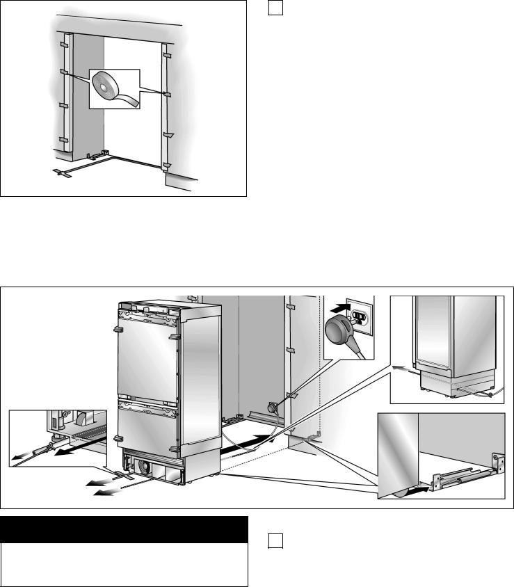
Orient ground prong to the bottom as shown |
in theshut off valve |
directly |
next |
to |
the appliance |
(base |
unit |
pictures. |
or in another |
easily accessible |
location. |
|
|
||
When installing the water connection, observe the permitted installation areas for the pipe. For the permitted installation areas and dimensions see •Installation dimensions", page 9.
Additional grounding |
procedure |
|
The |
supply |
pipe |
can be |
located |
at |
the side |
on |
the |
||
Some local regulationsmay require |
a seperate ground. |
(a), |
at the |
side |
on the |
left |
(b) |
or |
underneath |
(c), |
pag |
||
In such cases, the required accesseory ground |
wire, Maximum outer |
diameter |
of |
the |
water pipe |
|
|
||||||
clamp and screw must be purchased seperately. |
(without fittings): |
|
|
13/32" (10mm). |
|
|
|||||||
Never ground the appliance to |
plastic plumbing |
lines,Attach a separate shut off valve for the water |
|
|
|||||||||
gas lines or water pipes. |
|
|
connection |
in |
a |
suitable, |
easily accessible location. |
||||||
|
|
Do not use |
a |
self piercing valve! |
|
|
|
|
|||||
|
|
|
|
|
|
|
|||||||
8
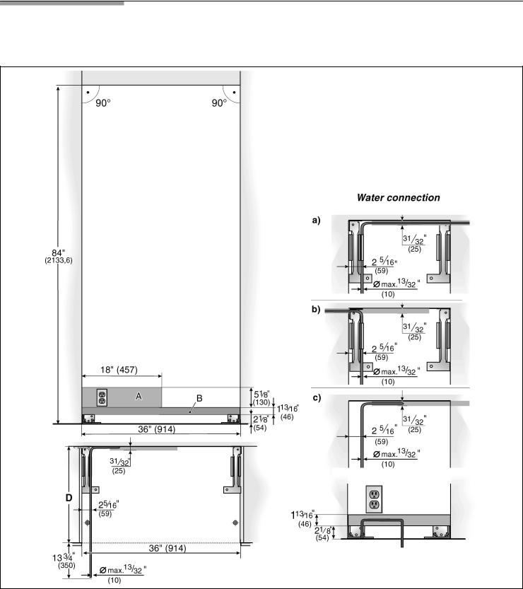
Installation dimensions
Single installation
Legend: |
|
|
|
|
|
|
A |
Area |
for |
installation of |
the |
power |
connection |
B |
Area |
for |
installation of |
the |
water |
connection |
D Opening |
depth |
of |
niche, depending on kitchen design |
(see DESIGN GUIDE) |
|
||
D = 24" (610 mm) minimum |
|||
NOTE: Cavity must be suare. |
|||
Side |
wall |
of |
the cavity must be flush. |
9
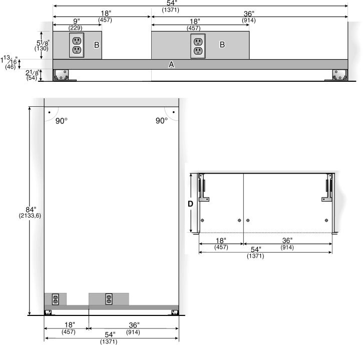
Side$by$Side installation
The cavity dimensions indicated above for the
respective |
appliance apply |
to a Side by Side installation |
|
of two appliances. |
|
||
The |
total |
width of the cavity results from the addition of |
|
the |
cavity |
widths indicated |
fortwotheappliances. |
|
|
|
|
|
|
|
|
Legend: |
|
|
|
|
A |
Area |
for |
installation of the water connection |
|
B |
Area |
for |
installation of the power connection |
|
D |
Opening |
depth |
of niche, depending on kitchen design |
|
|
(see DESIGN GUIDE) |
|||
|
D = |
24" |
(610 |
mm) minimum |
NOTE: Cavity must be suare.
Side wall of the cavity must be flush.
10
Appliance dimensions
Front view
(without door panel)
Legend: |
in levelling legs |
|
/+1" (35 |
mm) // "- (13 |
mm). |
e) |
Unit |
dimensions |
|
dimensions |
|||
a) |
Adjustment |
|
f) |
Wooden door panel |
|||||||||
|
|
|
3 |
8 |
1 |
2 |
|
|
|
|
|
|
|
|
Dimensions |
may vary. |
|
|
|
Note: |
One |
design |
of |
the wooden panel displayed. For further informa: |
|||
b) |
|
|
|
|
|
||||||||
c) |
Thickness |
of door panel may vary. |
|
|
|
|
|
tion |
about |
the |
different styles check the DESIGN GUIDE. |
||
d) |
This dimension may vary depending |
on installation, |
panel |
thickness |
|
|
|
|
|
||||
|
and kitchen hardware. |
|
|
|
|
|
|
|
|
|
|
|
|
11

Required |
accessories |
and tools |
|||||
1. |
Supplied |
accessories |
- |
Cutter |
with |
adjustable blade |
|
- |
Installation |
instructions |
- |
Metal |
tape |
measure |
|
|
|
|
|
||||
- |
Operating |
instructions |
- |
Square |
|
|
|
- |
Installation |
kit |
|
- |
Spirit level length 2' cm)(60 and 4' (1,2m) |
||
2. |
Optional |
accessories |
- |
Marking out level, length at least 4'm)(1for.2 |
|||
|
individual appliances or 7' m)(2.0for Side by Side |
||||||
Basic Combination |
Side$by$Side Sealing kit |
|
installation |
|
|||
|
|
|
|
||||
For |
permanent connection twof |
individual |
appliances, |
|||||
e. g. |
|
Freezer next |
to Refrigerator. |
|
|
|||
Extreme Combination |
Side$by$Side |
Heating kit |
||||||
If the |
gap |
between the appliances |
is |
less than |
||||
6" (160 mm). |
|
|
|
|
|
|||
Extra long finger protection part |
|
|
||||||
Panel |
unification |
part |
(Metal |
strip) |
|
|||
For |
connection twof |
furniture doorsCan. be used |
||||||
for standard |
height |
furniture doors without further |
||||||
preliminary |
work. |
|
|
|
|
|
||
5. Other
-Stepladder
- Dolly, hand truck
- Hammer drillfor drilling holes in wall or floor
- Bits according suitable for material and in different sizes
-Wooden beam (cross section min. 3" x 4" (75 cmx100 cm)) as an alternative tilt protection,
length according to the width of the installation cavity
3.Other required accessories from specialist outlets
Ice maker installation ¼"kit OD copper line
- Wooden screws in different sizes
-Thin (max.1/16" (1.5 mm)), suitable material to protect the floor from damage (e.g. lino)
For |
connecting appliances which require water, e.g. for- |
an |
ice maker. |
Suitable material for covering and protecting furniture (e.g. protective sheets)
i Maximum outer diameter |
of the water pipe |
- Adhesive tape |
|
||
(without fittings): |
13/ " (10mm). |
|
|
32 |
|
4. Tools
-Cordless screwdriver T20
-Torx screwdriver T20
- Torx bit T20 + magnetic holder - 5/16" (8mm) hex nut driver
- Wood drills in different sizes - Open end wrench½" (SW 13mm)
-Multigrip pliers
-Adjustable wrench
12
Installation |
instructions |
|
|
|
|
|
|
|
||||
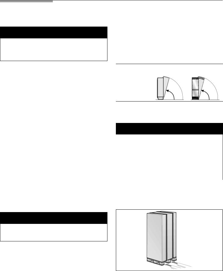
1. |
Checking the |
installation |
cavity The |
appliance |
is |
2134mm |
tall. If the appliance cannot |
|||||
|
|
|
|
|
|
be |
transported |
in |
an |
upright position due |
to the |
|
d |
|
CAUTION |
d |
structural conditions, |
the |
appliance can be |
transported |
|||||
|
|
|
|
|
|
horizontally. |
|
|
|
|
|
|
To ensure a safe, trouble free installation and an optimum overall view of the subsequent furniture front, thoroughly check that the installation cavity complies with the installation requirements.
When erecting the appliance, observe the required minimum height at the installation location according t the following table:
Before starting the installation, check that the installation |
|
|
|
|
|
|
|
Appliance width |
Erection |
via |
Erection |
via |
|
cavity complies with all requirements for a safe and |
|
appliance |
rear |
appliance |
side panel |
|
trouble free installation. |
|
|
|
|
|
|
qCheck the base.
Follow the instructions in the section on •Installation location" on page 7.
q |
Check |
the dimensions of the cavity. |
36" / 914 mm |
86" / 2185 mm |
911/4" / |
2315 mm |
|||||||||||||
q |
Check |
that the |
cavity |
is square. |
|
|
3. |
Removing |
the |
packaging |
|
||||||||
q |
Check |
location |
of the |
socket. |
|
|
|||||||||||||
|
|
|
|
|
|
|
|
|
|
|
|
|
|||||||
|
Also follow the instructions in the section on |
d |
|
|
WARNING |
|
d |
||||||||||||
|
•Connecting the power" on page 8 and in the |
|
|
|
|
|
|
|
|
|
|
|
|||||||
|
- The appliancemay tip over while it is being |
|
|||||||||||||||||
|
section on •Installation |
dimensions" |
on page 9. |
|
|||||||||||||||
q |
Check |
location of the water connection. |
unpacked. |
|
|
|
|
|
|
|
|||||||||
- |
The appliance is very heavy. |
|
|
|
|||||||||||||||
|
(only for appliances with ice maker) |
|
|
|
|||||||||||||||
|
Also follow the instructions in the section on |
- |
When opening the appliance door, the appliance |
||||||||||||||||
|
•Connecting the |
water" on |
page |
8. |
|
may tip |
forwards. |
|
|
|
|
|
|||||||
q |
Check |
attachment of |
the |
adjacent |
furniture/fixtures. |
Be |
careful, otherwise peoplewho are helpingmay be |
||||||||||||
|
All furniture parts in the vicinity |
of |
the appliance |
injured or |
the |
appliancemay |
be damaged. |
|
|
||||||||||
|
must |
be connected securely |
to |
the |
wall. |
To |
protect |
the |
base |
from |
damage |
during |
installation: |
||||||
|
Check |
|
|
|
|
|
|
|
|||||||||||
q |
that adjacent furniture/fixtures do not collide |
Attach |
a |
residual |
piece |
of carpet, lino, etc. to th |
|||||||||||||
|
(door |
opening angle). |
|
|
|
|
|
q |
|||||||||||
|
|
|
|
|
|
|
|
|
|
floor with adhesive tape in front of the intended |
|||||||||
2.. Transport |
of |
the |
appliance |
|
installation |
location. |
|
|
|
|
|||||||||
|
|
|
|
|
|
|
|
|
|
|
|||||||||
d CAUTION d
The appliance is very heavyBe. careful, otherwise people who are helpingmay be injured or the appliance may be damaged.
qTransport the appliance to a suitable installation location with suitable means of transportation
(trolley, lifting truck or hand driven truck).
qSecure the appliance during transportation to prevent it from overturning.
q Move the appliance with a hand truck securely.
13
q Remove transportation packaging:
-Remove the cartoonUse. the cutter securely to
protect the surface of appliance.
-Take supplied accessories out of protection parts of packaging.
5. Changing over the door hinges
d CAUTION d
d |
|
CAUTION |
d |
The door hingesmay have to be changed over |
|||||
|
|
depending on the installation situation. |
|||||||
Do not remove transportation safety devices which |
|||||||||
protect the shelves and storage |
compartments inside |
i |
If it is |
not necessary |
to change over the door hi |
||||
the appliance |
until the installation is complete, |
|
continue |
with the next |
installation step. |
||||
otherwise |
the |
partsmay be damaged. |
|
|
|
|
|
||
|
|
|
|
|
|||||
|
|
|
|
|
|
|
|
|
|
q Check appliance for damage in transit.
Do |
not install the |
appliance if it is visibly damaged |
If in |
doubt, contact |
your dealer. |
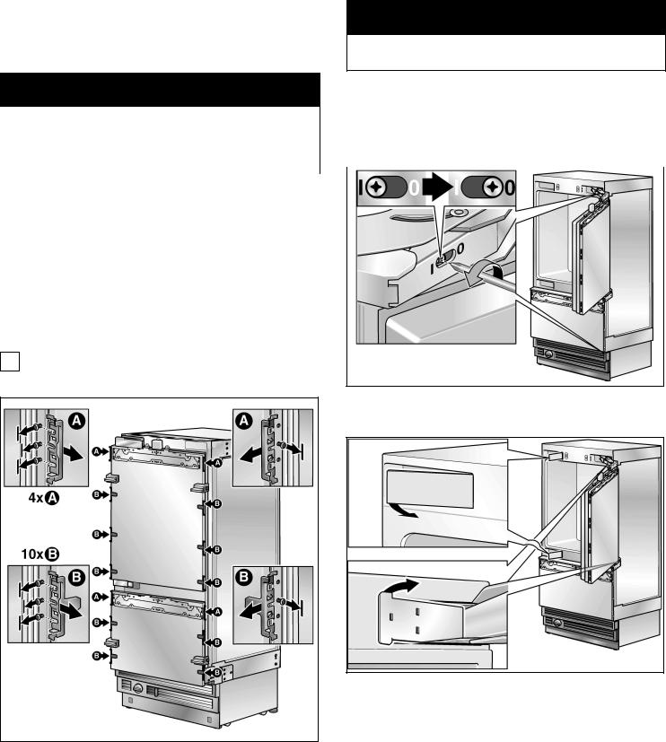
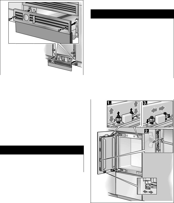
4. Preparing the appliance
qRemove the side brackets and fixing plates which
attach |
the |
furniture |
fronts. |
|
To |
do |
this, |
loosen |
the fastening screws and remove |
the |
stop parts. |
|
||
iStore the stop parts in suitable receptacles, otherwise theymay get lost.
q Release the spring on the hinge. Loosen the scre from I to0.
q Remove the hinge box covers.
14

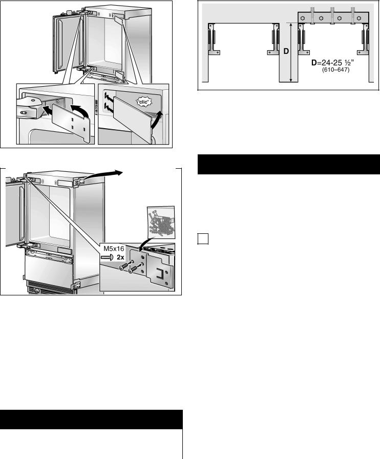
qUnscrew the door.
qRemove the hinges.
q Change over the fixation parts on the door.
qFix the hinges on the appliance. Change the hing crosswise!
qFix the door.
q Span |
the spring on the hinge. Tighten the screw |
from 0 |
toI. |
15
q If the |
installation cavity |
is deeper than |
the |
applian |
place |
a solid wooden |
beam behind the |
|
|
anti tip brackets and attach securely to |
the |
base o |
||
the wall. |
|
|
|
|
The length of the wooden beam is equal |
to the |
|||
width |
of the installation |
cavity! |
|
|
q Fix the hinge box cover.
! IMPORTANT NOTE !
If possible, always screw the wooden beam to |
|
|
existing studs on the rear panel of the |
cavity. |
|
In some installations the sub flooring or |
finished |
floor |
may necessitate angling the wood screws used |
to |
|
fasten the anti tip brackets to the back |
wall. |
|
|
|
|
i
-
-
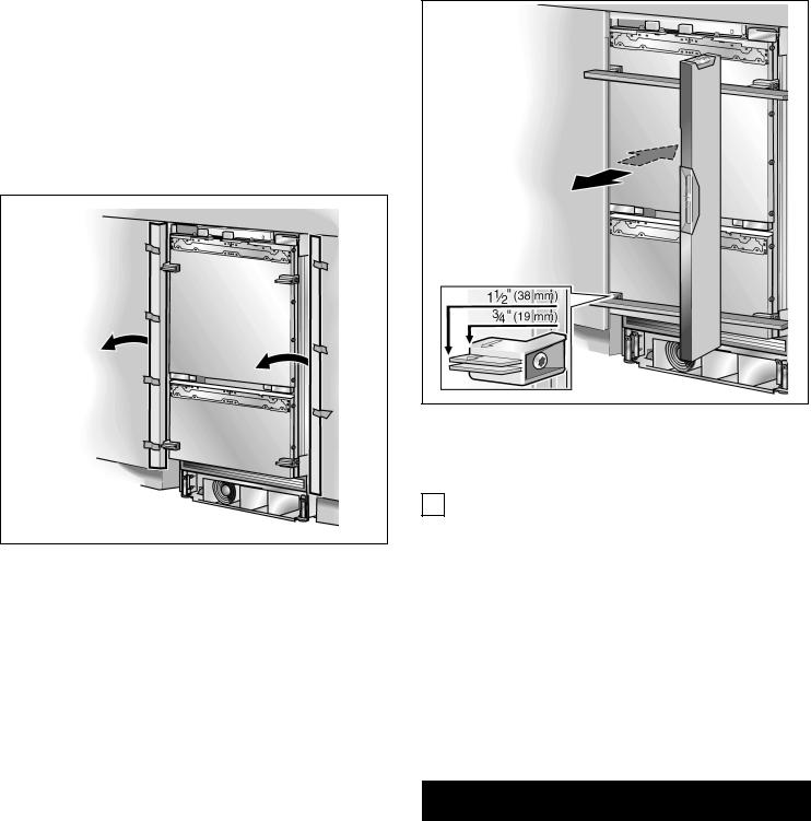
qChange the attachment plates.
6. Preparing the installation cavity
i |
2 |
anti tip brackets are required for each appliance |
|
or |
appliance combination (Side by Side). |
Important information for secure attachment of the anti tip brackets:
The supplied set contains fastening screws for various applications. Select the fastening screws according to the local conditions.
If the supplied fastening screws do not permit secure attachment of the anti tip brackets and therefore the appliance, another method must be used to attach the anti tip brackets securely.
qSpecify the attachment points of the anti tip brackets.
Specify the detailed dimensions according to the section on •Installation dimensions" starting on page 9.
d |
WARNING |
d |
|
|
|
|
|
Assure |
that there are no electrical wires |
or plumbing |
|
in the |
area which the screws could penetrate - risk of |
||
injury |
and damage! |
|
|
|
|
|
|
16
Wood |
floor application |
|
Use concrete anchorM8 andM8 srew. Additional use |
||
Use the |
wooden |
|
|
the wooden screws provided, see overview diagram |
|
screws provided, see overview diagram |
|||||
•Use |
the |
screws |
in the |
screws set". |
•Use the screws in the screws set". |
|
|||||
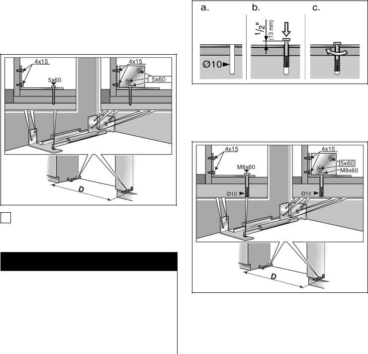
qDrill pilot holes:
1/8" (3mm) for the (5 xmm)60 wooden screws
5/64" (2mm) for the (4 xmm)15 wooden screws
Being certain the screws penetrate |
through |
the flooring and into the wall plate |
a minimum |
of 3/ " (19 mm). |
|
4 |
|
qAttach the anti tip bracket completelyBe. sure screws hold tight.
q Drill |
a 10mm diameter hole any depth exceeding |
the |
minimum embedmentUse. the provided drill. |
q Clean hole or continue drilling additional depth.
q |
Manually insert |
the screw into the wall plug until |
||
|
screw |
begins to resist. |
||
q |
Knock |
the |
wall |
plug and screw into the hole unti |
|
screw |
head |
is |
approx½". (13mm) from the anti tip |
bracket.
iThe distanceD between the anti tip brackets is adequately the width of the appliance.
Concrete |
floor applications |
|
|
|
|
|
|
|
|
|
|
|
|
|
|
||
d |
CAUTION |
d |
|
|
||||
|
|
|
|
|||||
Always wear safety glasses and other necessary |
|
|
|
|||||
protective devices or apparel when installing or |
|
|
|
|||||
working |
with anchors ? risk of |
injury! |
|
|
|
|
|
|
Not recommended for use in |
light weight |
masonry |
|
|
|
|||
|
|
i |
||||||
material |
such as block or brick. |
|
|
|
|
|
||
Not recommended for use in |
new concrete |
which |
has |
|||||
not had time to cure. |
|
|
|
|
|
|
||
Do not |
use core drills to drill |
holes for |
this |
anchor. |
||||
|
|
|
|
|
|
|
|
|
The distanceD between the anti tip brackets is adequately the width of the appliance.
17
7. |
Attaching |
an |
alternative |
anti$tip q |
Locate |
wall studs near |
the |
rear panel |
of |
the cavi |
||||||||||||||||||||||
|
device |
|
|
|
|
|
|
|
|
|
|
|
|
and mark |
drill holes |
in |
the |
beam. |
|
|
|
|
|
|||||||||
|
|
|
|
|
|
|
|
|
|
|
|
|
Predrill |
the |
wooden |
beam. |
|
|
|
|
|
|
|
|||||||||
|
|
|
|
|
|
|
|
|
|
|
|
|
|
|
|
|
q |
|
|
|
|
|
|
|
||||||||
! |
|
|
|
IMPORTANT |
NOTE |
|
! |
|
|
|
|
|
|
|
|
|
||||||||||||||||
|
|
|
|
|
|
|
q |
Attach |
the |
wooden |
beam to the |
rear |
panel of |
th |
||||||||||||||||||
|
|
|
|
|
|
|
|
|
|
|
|
|
|
|
|
|
|
cavity. |
|
|
|
|
|
|
|
|
|
|
|
|
|
|
If possible, always screw the wooden beam to |
|
|
|
|
|
|
|
|
|
|
|
|
|
|
|
|
|
|||||||||||||||
|
|
|
|
|
|
|
|
|
|
|
|
|
|
|
|
|
|
|||||||||||||||
existing |
studs on the |
rear |
panel |
of the |
cavity. |
|
8. |
Preparing |
to |
|
connect |
the |
water |
|||||||||||||||||||
|
|
|
|
|
|
|
|
|
|
|
|
|
|
|
|
|
||||||||||||||||
If the anti tip |
brackets |
cannot |
be |
attached securely, |
|
|||||||||||||||||||||||||||
|
(only for appliances |
which |
|
require a water |
connection) |
|||||||||||||||||||||||||||
an alternative |
anti tip |
device |
can be attached. |
|
|
|
|
See also •Connecting the water". |
|
|
|
|
|
|
||||||||||||||||||
However, ensure that there is no play between the |
|
|
|
|
|
|
|
|||||||||||||||||||||||||
appliance |
|
and the anti tip |
device. |
|
|
|
|
|
|
|
|
|
|
|
|
|
|
|
|
|
|
|
|
|
|
|||||||
|
|
|
|
|
|
|
|
|
|
|
CAUTION |
|
|
|
|
|
|
|||||||||||||||
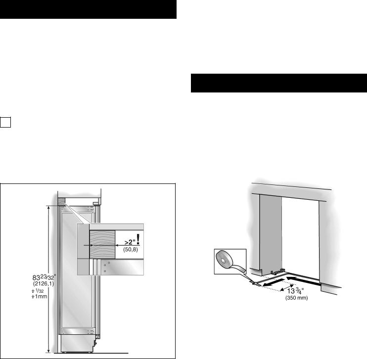
q |
Saw |
the |
wooden |
beam |
(cross section min. 3" x 4"d |
|
|
d |
|
|||||||||||||||||||||||
|
(75 |
cmx |
100 cm)) |
to |
|
the |
required length. |
|
Turn off the main water tap to prevent damage |
|
|
|
||||||||||||||||||||
|
|
|
|
|
|
|
|
|
|
|
|
|
|
|
|
|
|
|
||||||||||||||
|
Length |
is |
equal |
to |
the |
width |
of the |
installation |
|
caused by leaking |
water. |
|
|
|
|
|
|
|
|
|||||||||||||
|
|
cavity! |
|
|
|
|
|
|
|
|
|
|
|
|
|
|||||||||||||||||
i |
Note |
|
|
|
|
|
|
|
|
|
|
|
|
|
|
q |
Attach |
the |
connecting |
pipe |
to the |
shut off |
valve |
|
||||||||
|
|
|
|
|
|
|
|
|
|
|
|
|
|
|
|
|
|
according |
to the |
instructions |
supplied by the |
|
||||||||||
- |
If the |
installation |
cavity |
is deeper than the appliance,manufacturer of |
the |
ice |
maker installation |
kit. |
|
|||||||||||||||||||||||
|
select |
a |
beam which |
has |
a larger cross |
section |
|
or |
Install |
the |
connecting |
pipe. |
Always |
observe the |
|
|||||||||||||||||
|
attach |
2 |
beams. |
|
|
|
|
|
|
|
|
|
|
|
q |
|
||||||||||||||||
|
|
|
|
|
|
|
|
|
|
|
|
|
indicated gap dimensions to |
prevent damage to |
th |
|||||||||||||||||
|
|
|
|
|
|
|
|
|
|
|
|
|
|
|
|
|
|
|||||||||||||||
- |
The |
beam must |
cover |
|
the |
appliance |
by |
at least |
2" |
connecting |
pipe |
when |
pushing in |
the |
appliance. |
|
||||||||||||||||
|
(50.8 mm). |
|
|
|
|
|
|
|
|
|
|
|
|
|
|
|
|
|
|
|
|
|
|
|
|
|
|
|
||||
|
|
|
|
|
|
|
|
|
|
|
|
|
|
|
|
|
|
|
|
|
|
|
|
|
|
|
|
|||||
|
|
|
|
|
|
|
|
|
|
|
|
|
|
|
|
|
|
|
|
|
|
|
|
|
|
|
|
|
|
|
|
|
q Attach the connecting pipe to the floor with adhesive tape.
q Mark the installation |
height |
(lower edge of the beam) |
on the rear panel of |
the |
cavity. |
qSelect screws according to the thickness of the wooden beam: length = min. 2.5 x beam thickness,
diameter #12 or #14.
i |
Specify |
the |
number of screws according to the |
|
cavity |
width, |
thereby ensuring that the beam can |
|
be attached |
securely. |
|
18
9. Attaching the edge protection
qTo protect the corners of the installation cavity, attach the supplied protective brackets with adhesive tape.
10.Side$by$Side |
installation |
|
i If a side by side installation is |
intended, |
|
now connect thetwo |
appliances |
together. |
See the Installation Manual for |
the Side by Side kits. |
|
11. Pushing the appliance into the installation cavity
d CAUTION d
Caution when pushing the appliance into the installation cavity.Do not damage the water pipe or power cord attached to the floor.
q Put the mains plug into the socket.
iIn the case of Side by Side appliances a separate socket must be used for each appliance.
i |
When the floor or |
the appliance is |
tilted in |
|
comparison to the installation cavity adjust height |
||
|
adjustable wheels before you move |
the appliance |
|
|
into the installation |
cavity. |
|
19
12. Installing and aligning the cordappliance
qAlign the appliance with the furniture fronts.
Place marking out level over the installation aid parts on the door.
iThe installation aid parts on the door have been designed for the following total thickness of furnitu doors:
-3/4" (19mm)
-1/2" (38mm)
Always take account of the possible differing thickness of the furniture fronts which are to be fitted subsequently.
The height adjustable feet at |
the |
front and rear can |
||
be adjusted |
from the front. |
|
|
|
Front: |
with |
|
1 |
|
open ended wrench/2" (SW13) |
||||
Rear: |
with |
5/ " (8mm) hex |
nut |
driver |
|
|
16 |
|
|
|
via |
flexible shaft. |
|
|
|
d |
|
|
CAUTION |
|
d |
|||
|
|
|
|
|
|
||||
Never |
use |
a cordless screwdriver! |
|
|
|
||||
|
|
|
|
|
|||||
A |
mark |
is |
attached to the appliance base and is us |
||||||
a |
standard |
gage |
for |
height |
adjustment. |
When adjustin |
|||
the height, |
align |
this |
mark |
1 |
|
(32ofmm)1 |
|||
at a height/ " |
|||||||||
above the |
floor. |
|
|
|
4 |
|
|
||
|
|
|
|
|
|
||||
q
i
q
i
-
-
-
13. Attaching the appliance to the top of the cavity
|
|
|
|
|
|
q Screw the attachment plate lugs (top) to the |
|
Unscrew |
the height adjustable |
feet |
until the mark |
overhead furniture/fixtures. |
|||
|
|||||||
on the base has reached the indicated guide |
|
|
|||||
|
|
||||||
dimension |
(1/4" / 32mm). |
|
|
|
|
|
|
It is |
very |
important to comply with this |
dimension |
|
|||
the |
subsequent alignment of |
the |
furniture |
fronts. |
|
||
Align the furniture fronts with the spirit level.
Note: |
|
|
|
|
|
|
|
|
|
Do not twist or jam the appliance inside the cavity! |
|
|
|
|
|
|
|||
When unscrewing the height adjustable feet, |
|
|
|
|
|
|
|||
proceed gradually: Always alternate between left |
|
|
|
|
|
|
|||
and right, left and right, etc.. |
|
|
|
|
|
|
|||
The adjustment of the rear feet is facilitated if the |
|
|
|
|
|
|
|||
appliance is |
unloaded at the rear. |
|
|
|
|
|
|
||
If using a wooden beam as an alternative anti tip |
|
|
|
|
|
|
|||
device according to point 5 of this installation |
|
|
|
|
|
|
|||
manual, rotate the appliance allwaythe towards |
|
|
|
|
|
|
|||
the wooden |
beam. |
|
|
|
|
|
|
|
|
q Fix |
the |
attachment plate side lugs (top) depending |
|||||||
|
|
||||||||
|
|
on |
the |
installation |
situation. If there |
is |
no gap or |
||
|
|
a |
slight |
gap, it is |
not necessary to |
fix |
the side |
||
qIf there is a fairly large gap above the appliance,
wooden beam above |
the |
appliance, ensuring that |
the wooden beam fits |
the |
gap exactly. |
21
15. Connecting the water to the appliance
i When connecting the water pipe to the solenoid valve of the appliance, follow the instructions supplied by the manufacturer of the ice maker installation kit enclosed with the installation manual
d |
CAUTION |
|
d |
|||
|
|
|
|
|||
When bending the water pipe, do not |
kink |
it, |
|
|
||
otherwise there is a risk of leaks |
and |
water |
|
damage |
||
Use |
bending aids. |
|
|
|
|
|
|
|
|
|
|
|
|
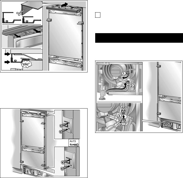
qAttach the cover strip to the attachment plate (top)
Shorten the fitting strip to the required height!
14.Attaching the individual appliance to the side of the cavity
qScrew the attachment plate lugs (side) to the adjacent furniture/fixtures (individual appliances only).
q Remove the cap from the appliance connection1.
qBend the water pipe according to the location of
connection on the appliance2.
q Push the union nut and seal onto the water pipe
qPush the end of the water pipe into the applianc connection and screw on the union3. nut
Tighten hand tight.
q Using |
the |
open ended wrench, tighten the union |
nut. Do |
not |
overturn! |
qOpen the shut off valve and main water tap.
Check the connection |
on the shut off valve and |
on the appliance for |
leaks. |
22
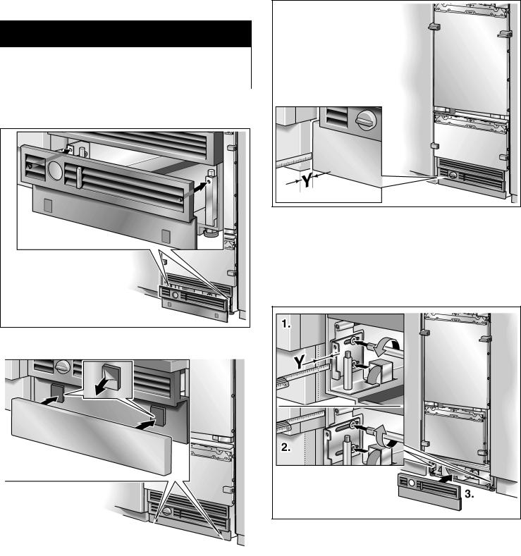
16. Attaching the toe kick panel
d |
|
CAUTION |
d |
|
|
|
|
|
|
The |
maximum |
height of the toe |
kick panel is |
4" |
the |
top of the |
floDor. not cover ventilation slots |
in |
|
the |
base panel. Risk of damage to the appliance. |
|||
|
|
|
||
q If |
required, cut the toe kick panel to the required |
|||
length. |
|
|
|
|
q |
Put on |
the |
base panel (do not screw on) and |
|
|
measure the difference in depth Y between the b |
|||
|
panel and toe kick |
panel of the adjacent furniture |
||
q |
Remove |
the |
base panel. |
|
q |
Loosen |
the |
brackets |
for attaching the base panel |
|
and push in |
all the |
way. |
|
q Attach the base panel to the appliance.
|
|
|
|
|
q |
Pull out the brackets by the measured Yamount. |
|
|
|
|
|
q |
Screw the brackets tightly. |
|
|
|
|
|
||
q |
Remove |
the protective film from the adhesive pads |
|
|||
|
on |
the |
Velcro. |
|
||
q |
Fit |
the |
toe |
kick panel to the base panel and press |
|
|
|
firmly into |
place. |
|
|||
23
18. Preparing the furniture doors
|
|
|
|
|
|
! |
|
|
|
|
IMPORTANT |
NOTE |
! |
|
|
|||||||
|
|
|
|
|
|
|
|
|
|
|
||||||||||||
|
|
|
|
|
|
|
|
When performing any work on the furniture doors, |
||||||||||||||
|
|
|
|
|
|
|
|
always |
observe the |
following: |
|
|
|
|
|
|
||||||
|
|
|
|
|
|
|
- |
Always |
screw into the best load bearing material |
|||||||||||||
|
|
|
|
|
|
|
|
|
of |
|
the |
furniture |
door. |
|
|
|
|
|
|
|
||
|
|
|
|
|
|
|
- |
Never |
screw into fillers, decorative strips |
or similar |
||||||||||||
|
|
|
|
|
|
|
- |
Select |
a |
screw |
length |
which |
is |
always |
shorter tha |
|||||||
|
|
|
|
|
|
|
|
|
the |
thickness of |
the furniture |
front. |
|
|
|
|||||||
|
|
|
|
|
|
|
|
- To |
prevent damage, protect surfaces of the |
|||||||||||||
|
|
|
|
|
|
|
|
|
furniture doors during |
installation. |
|
|
|
|||||||||
|
|
|
|
|
|
|
|
The total weight of the furniture front must not |
||||||||||||||
|
|
|
|
|
|
|
|
exceed |
the |
following values: |
|
|
|
|
|
|
||||||
|
|
|
|
|
|
|
|
BM |
36" |
(top, 1 door) |
55 |
lbs |
/ 25 kg |
|
|
|
||||||
|
|
|
|
|
|
|
|
BM |
36" |
(bottom) |
|
22 lbs |
/ |
10 kg |
|
|
|
|||||
q Attach the |
base |
panel. |
|
|
|
|
|
|
|
|||||||||||||
|
|
|
|
|
|
|
|
|
|
|
|
|
|
|
|
|
|
|
||||
|
|
|
|
The |
furniture |
fronts |
are attached to the appliance doo |
|||||||||||||||
|
|
|
|
|
|
|
|
|||||||||||||||
i |
If required, |
the |
toe kick |
panel |
|
|
|
by |
means |
of |
fitting |
parts |
on |
the |
appliance. |
These fitt |
||||||
|
can be screwed to the |
|
|
|
|
|
|
|
|
|
|
|
|
|
||||||||
|
base panel. There are screw holes in the |
|
|
parts allow the furniture door |
to |
be adjusted precisely |
||||||||||||||||
|
base panel |
|
|
|
|
|
|
|
|
|
|
|
|
|
||||||||
|
near the Velcro. |
|
|
|
|
|
and |
attached |
securely to |
the |
appliance. |
|
|
|
||||||||
|
|
|
|
|
|
|
|
|
|
|
|
|
|
|
|
|
|
|||||
17. Commissioning |
the |
Appliance |
|
|
|
|
|
|
|
|
|
|
|
|
|
|
||||||
To guarantee the accuracy of the following working |
|
|
|
|
|
|
|
|
|
|
|
|
|
|
||||||||
steps and thus the appearance of |
the overall |
kitchen |
|
|
|
|
|
|
|
|
|
|
|
|
|
|
||||||
front later on, |
the |
appliance |
should |
now be |
operated |
|
|
|
|
|
|
|
|
|
|
|
|
|
|
|||
q Open the appliance door.
qPress thePOWER button.
Only for appliances with a water connection:
! NOTE !
|
|
|
In order to avoid the risk of damage caused by |
||
leaking water from damage possibly caused to the |
||
water |
pipe feeding the appliance, keep the shut off |
|
valve |
closed. |
|
|
|
|
4.
24
Function |
of |
different parts: |
|
|
|
||||
1. |
Double threaded |
bolt |
on |
the |
adjusting |
rail: |
|||
|
for vertical |
adjustment |
of |
the |
furniture door. |
||||
2. |
Side |
brackets: |
|
|
|
|
|
||
|
for adjusting |
the |
depth of the furniture |
front. |
|||||
3. |
Nuts |
on |
the |
double |
threaded |
bolt: |
|
||
for securing the furniture front to prevent lateral movement.
4.Lower brackets:
for securing the furniture front to prevent lateral movement.
19. Loading the appliance door
When attaching |
the |
furniture doors, |
|
it is |
recommended |
|||
to load the door storage compartments |
in the |
applian |
||||||
with weights in order to ensure that the |
gap |
width i |
||||||
precise as possible. |
|
|
|
|
|
|
|
|
Recommendations: |
|
|
|
|
|
|
|
|
Refrigerator compartment |
55 |
lbs |
/ |
25 |
kg |
|
||
Freezer compartment |
|
22 |
lbs |
/ |
10 |
kg |
|
|
20. Attaching |
the |
adjusting |
rail |
|
||||
to the |
furniture |
|
door |
|
|
|
||
(refrigerator compartment)
iThe adjusting rail is the most important means of adjusting the furniture front.
|
|
|
|
|
|
|
|
|
|
|
|
|
|
|
|
|
|
|
|
|
|
|
|
|
|
|
|
|
|
|
|
|
|
|
|
|
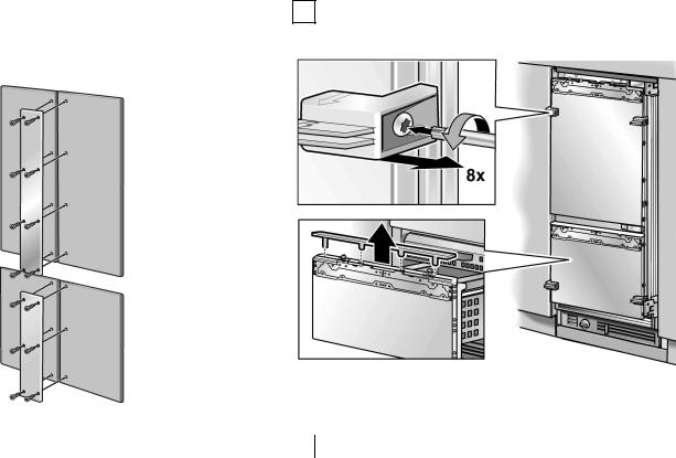
q |
|
Unscrew the installation support part from the |
||||||||
|
|
|
|
|
|
|
appliance |
doors. |
|
|
|
|
|
||
When attaching the metal strip to the furniture doors, |
|
|
|
|
|
|
|||||||||
|
|
|
|
|
|
|
|
|
|
||||||
andStore the |
positioning aids, there |
will |
be |
used in |
|||||||||||
observe the |
maximum possible length of the |
screws |
|||||||||||||
|
|
|
|
|
i |
|
|
|
|
|
|
|
|
|
|
the position |
of the drill holes. Always screw into the |
|
an installation |
step |
later. |
|
|
|
|
||||||
best |
|
|
|
|
|
|
|
||||||||
load bearing |
material of |
the furniture door. |
|
|
q |
|
Remove the cover plate from the freezer |
|
|
||||||
|
|
|
|
|
|
|
|
||||||||
Never screw |
into fillers, |
decorative strips or |
similar. |
|
compartment |
door. |
|
|
|
|
|
||||
|
|
|
|
|
|
|
Check the |
double |
threaded bolts |
on |
the |
adjusting |
|||
|
|
|
|
|
i |
|
|||||||||
|
|
|
|
|
|
|
rail. Both |
of |
them |
must project |
out |
of the door |
|||
|
|
|
|
|
|
|
3/ " (5mm). |
|
|
|
|
|
|
||
|
|
|
|
|
|
16 |
|
|
|
|
|
|
|
||
25
i |
Note |
|
|
|
|
|
- |
Attach |
the |
adjusting |
rail to |
the furniture door with |
|
|
least 10 screwsOne. screw should be inserted |
|||||
|
under |
each |
double |
threaded |
bolt. |
|
|
|
|
|
|
|
|
|
|
|
|
|
|
|
- The adjusting |
rail features a variety of holes for t |
|
many different design options of furniture doors. |
||
Always |
screw |
into the best load bearing material |
of the |
furniture |
door. |
- Never screw into fillers, decorative strips or similar.
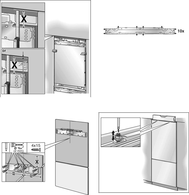
21. Attaching and aligning the furniture door (refrigerator compartment)
|
|
|
i |
The |
double threaded bolts |
are |
responsible for |
|
|
|
|
adjusting the height of the |
furniture front. |
||
q Measure |
the distanceX between the adjusting rail |
|
|||||
q |
Hang |
the furniture door on |
the |
double threaded |
|||
and the |
overhead furniture/fixtures. |
|
bolt. |
|
|
|
|
|
|
|
|
|
|
|
|
q Loosen the 2 nuts and remove the adjusting rail.
|
|
|
|
|
|
q Align the furniture door with the double threaded |
|
|
|
|
|
|
|
q |
Mark this amountX on the rear of the furniture door. bolts (Torx screwdriver). |
|||||
q |
Determine |
and |
mark the |
centre of the furniture door. |
||
q |
Put on the adjusting rail |
and align along the marks. |
||||
|
Mark |
the |
drill |
holes. |
|
|
q |
Drill |
the |
holes. |
|
|
|
q |
Screw on the |
adjusting |
rail tightly. |
|||
26

q |
Transfer |
the |
middle |
drill |
holes |
along the outer edge |
fixing plates (10x). |
||
|
of the |
appliance door to |
the |
|
|
q Screw on the |
|||
|
furniture front and mark. |
|
|||||||
q |
Remove |
the |
furniture |
door. |
|
|
22. Attaching |
the adjusting rail |
|
|
|
|
|
|
|
|
|
(freezer compartment) |
|
|
|
|
|
|
|
|
|||
|
|
|
|
|
|
|
|
|
|
|
|
|
|
|
|
|
|
|
|
|
|
|
|
|
|
|
|
q |
Measure |
the distanceY between the adjusting rail |
|
|
|
|
|
|
|
|
|
|
and the |
upper |
door. |
|
|
|
|
|
|
|
|
q |
Loosen |
the 2 |
nuts and remove the adjusting rail. |
|
|
|
|
|
|
|
|
||||
q |
Using |
the positioning |
aid, set both longitudinal sides |
|
|
|
|||||
|
of the |
furniture |
door |
parallel. |
|
|
|
|
|
||
q |
Using |
a |
square, |
extend |
the |
drill hole marks which |
|
|
|
||
|
you have |
just made |
to |
the |
vertical marks. |
|
|
|
|||
q Mark and drill the holes.
q Mark this amountY on the rear of the furniture doo q Determine and mark the centre of the furniture do
27
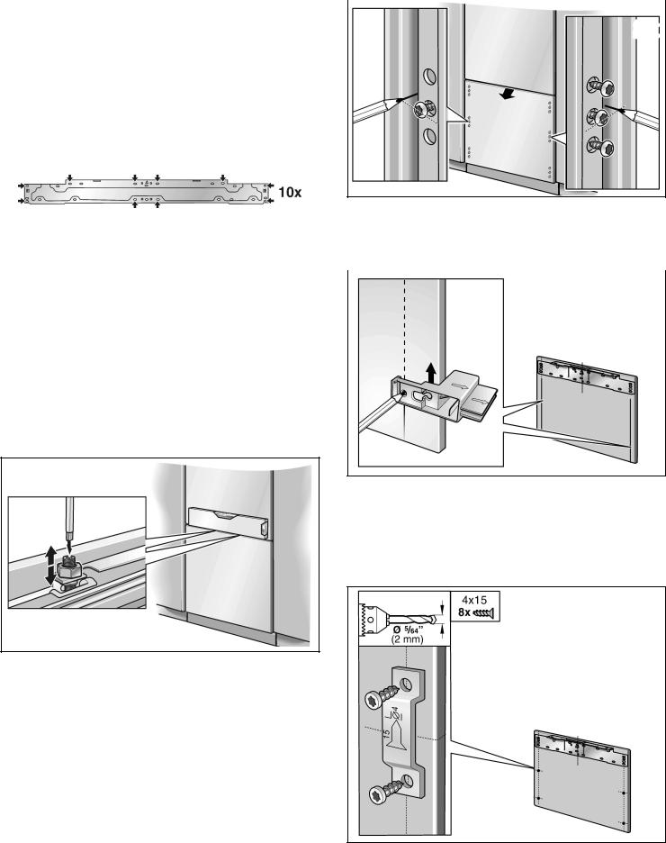
q |
Put |
on the adjusting rail and |
align along the marks |
|
|
|
Mark |
the |
drill holes. |
2x |
2x |
q |
Drill |
the |
holes. |
|
|
|
|
||||
q Screw on the adjusting rail tightly.
i |
Note |
|
|
|
- |
Attach |
the |
adjusting |
rail to the furniture door with |
|
least 10 screwsOne. screw should be inserted |
|||
|
under |
each |
double |
threaded bolt. |
|
|
|
|
q |
Transfer |
the middle drill holes along the outer edg |
||
|
|
|
|
|||||
- The adjusting |
rail features a variety of holes for |
the of the |
appliance door |
to the furniture front and m |
||||
many |
different |
design options of furniture doors. |
q |
Remove |
the furniture |
door. |
||
Always |
screw |
into the best load bearing material |
|
|
|
|
|
|
|
|
|
|
|
||||
of the |
furniture |
door. |
|
|
|
|
|
|
23.Attaching and aligning the furniture door
(freezer compartment)
i |
The double threaded bolts |
are |
responsible for |
|
adjusting the height of the |
furniture front. |
|
q |
Hang the furniture door on |
the |
double threaded |
|
bolt. |
|
|
q |
Mark |
a vertical line under the outermost fixing hol |
|||||
|
in the |
adjusting |
rail. |
|
|
||
q |
Using |
a square, |
extend |
the |
drill hole marks which |
||
|
you have |
just |
made to |
the |
vertical marks. |
||
q |
Mark |
and |
drill |
the holes. |
|
||
q Align |
the furniture door with the double threaded |
bolts |
(Torx screwdriver). |
q Screw on the fixing plates (4x).
28
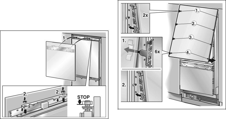
24. Attaching the furniture door (refrigerator compartment)
i |
Now |
fit the furniture handles which are screwed |
|
from |
behind! |
q Attach the bracket:
qHang the furniture doors with adjusting rail over the - double threaded bolts.
Lift the furniture door slightly away from the appliance door.
q Screw the nuts a little onto the double threaded bolts. Do not tighten!
qPrecisely adjust the furniture door.
Align |
the |
furniture door with the double threaded |
bolts |
(Torx |
screwdriver). |
- |
Push |
the side |
bracket |
on |
the |
left |
and |
right |
o |
|
|
the |
screws1. |
|
|
|
|
|
|
|
|
- |
Insert |
the side |
bracket |
on |
the |
left |
and |
right |
i |
|
|
the |
fixing plate and slide over the2screw. |
|
|||||||
|
Slowly |
lower the door. |
|
|
|
|
|
|
||
q Align |
the furniture |
doors, checking the clearance all |
Continue |
the |
process until the last side |
brackets |
|||||||
the way |
round. If |
required, move the adjusting rail to |
(4.) have been inserted |
into |
the |
fixing |
plates and |
||||||
the |
left |
or right. |
|
|
|
are positioned |
on |
the screws. |
|
|
|
||
|
|
|
|
|
|
|
|
|
|
|
|||
|
|
|
|
|
|
The two |
upper |
brackets1.( ? on the left and right) |
|||||
|
|
|
|
i |
|
||||||||
|
|
|
|
|
|
have no |
side |
piece for insertion into the fixing pl |
|||||
|
|
|
|
q |
Close the door and check that the depth of the |
||||||||
|
|
|
|
|
|
furniture |
front |
is |
aligned |
with |
the |
adjacent fronts. |
|
|
|
|
|
|
|
If required, correct. |
|
|
|
|
|||
|
|
|
|
q |
Tighten the bracket screws to fix the depth |
||||||||
|
|
|
|
|
|
alignment. |
|
|
|
|
|
|
|
|
|
|
|
q |
Close the door and check the side alignment. |
||||||||
|
|
|
|
|
|
Correct by gently tapping the edge of the open |
|||||||
|
|
|
|
|
|
furniture |
door |
with your |
hand. |
|
|
|
|
29
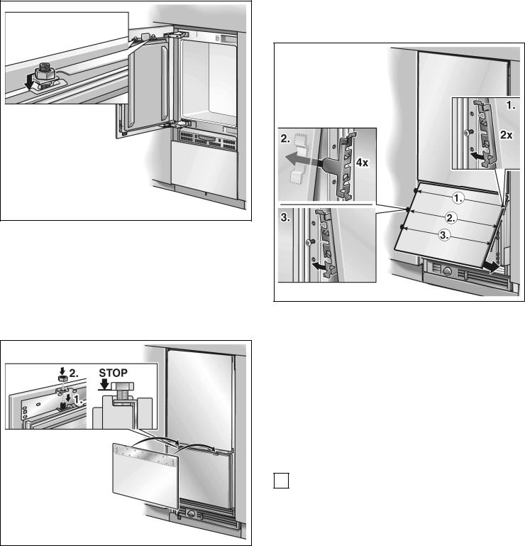
q Precisely adjust the furniture |
door. |
||
Align |
the |
furniture door with |
the double threaded |
bolts |
(Torx |
screwdriver). |
|
q Tighten the nuts |
on |
the adjusting rail. This will fix |
side alignment of |
the |
door. |
25.Attaching the furniture door (freezer compartment)
i |
Now |
fit the furniture handles which are screwed q |
|
from |
behind! |
i
q
q q Hang the furniture door with adjusting rail over the
double threaded bolts.
q Screw the nuts a little onto the double threadedq bolts. Do not tighten!
Attach the bracket:
-Lift the furniture door slightly away from the appliance door.
- |
Push |
the |
side bracket on the left |
and |
right |
o |
|
the screws1. |
|
|
|
||
- |
Insert |
the |
side bracket on the left |
and |
right |
i |
|
the fixing plate and slide over the2screw. |
|
||||
|
Slowly |
lower the door. |
|
|
|
|
Continue |
the process until the last side brackets |
|||||
(3.) |
have |
been inserted into the fixing |
plates and |
|||
are positioned on the screws. |
|
|
|
|||
The two upper |
brackets1.( ? on the left |
and |
right) |
|||
have no |
side |
piece for insertion into the fixing |
pl |
|||
Close the door and check that the depth of the furniture front is aligned with the adjacent fronts. If required, correct.
Tighten the bracket screws to fix the depth alignment.
Close the door and check the side alignment. Correct by gently tapping the edge of the open furniture door with your hand.
30
 Loading...