


BeoVision 4
Table of contents
 Loading...
BeoVision 4
Reference book
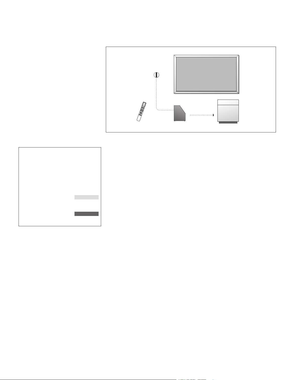
BeoVision 4 includes the products shown above.
The individual components are referred to by their
respective names in the Guide and Reference
book. The complete setup is referred to as
BeoVision 4.
BeoVision 4
plasma screen
IR receiver
Beo4
remote control
An explanation of symbols
in the Guide and Reference
book
Buttons on the Beo4 remote
control
Display on the Beo4 remote
control
Display on the screen
TV
LIST
m
p
ST ORE
TV 12
BeoSystem 2
Cabinet
The Guide and the Reference book
This Reference book contains information about connecting and operating external
equipment, as well as an overview of on-screen menus. The Guide contains all the
information you need to know about your Bang & Olufsen products.
We expect your Bang & Olufsen retailer to deliver, install and set up your products.
However, the information required to install and set them up is included in the
Guide and the Reference book. This might be useful if you move your products or
expand your system at a later date.
The Guide and the Reference book both contain an index which can help you find
the specific subject you want to know more about.

Contents
3
Placement, connections and maintenance, 4
Find out how to handle and place your BeoVision 4, connect additional video
equipment, and where the sockets are placed.
Loudspeaker setup – surround sound, 13
Find out how to turn BeoVision 4 into a surround sound system.
Connect extra equipment, 18
Find out how to connect a set-top box, decoder, High Definition (HD) source or a
PC to BeoSystem 2 and how to register extra equipment.
Audio system with BeoVision 4, 26
Find out how to connect an audio system to BeoSystem 2 and operate an
integrated audio/video system.
Distribute sound and picture with BeoLink, 28
Find out how to make link connections, operate a link system and set up
BeoVision 4 in a link room.
Customise Beo4, 32
Find out how to add and remove Beo4 functions.
Menus, 34
Overview of the on-screen menus.
Index, 41
4
Set up BeoVision 4 and BeoSystem 2
We recommend that you follow the
procedure described below when you
set up BeoVision 4:
– Unpack the system and the screen.
– Consider the appropriate
surroundings. Guidelines are
included on this page.
– Mount the wall bracket as
described in the Guide enclosed
with the wall bracket.
– Connect the screen.
– Mount the IR receiver.
– Connect speakers and additional
equipment, as described on the
following pages.
Do not connect your system to the
mains until you have connected your
screen, loudspeakers and other
equipment!
For further information about the
close-up socket panel on BeoSystem 2,
refer to the chapter ‘Close-up socket
panel on BeoSystem 2’ on page 12.
Before you start…
– Make sure that your products are set up,
placed and connected in accordance with
this Guide.
– Do not place any items on top of
BeoSystem 2 or the screen.
– Your products are developed for indoor
use in dry, domestic environments only,
and for use within a temperature range of
10– 40 ºC (50–105ºF).
– Do not attempt to open your products.
Leave such operations to qualified service
personnel.
BeoSystem 2:
– Place BeoSystem 2 in the Cabinet. If you do
not wish to use the Cabinet, make sure that
there is sufficient space around BeoSystem 2
for ventilation.
– Always place BeoSystem 2 on a firm and
stable surface.
The plasma screen:
– Due to the weight of the screen, any
moving or lifting of the screen should be
done by two persons.
– When lifting the screen, grip the top and
bottom edges.
– Carry the screen in such a way that it is in
an upright position at all times.
– If you must put the screen down at any
time prior to placing it, we recommend
that you rest it in an upright position on its
bottom edge on a stable, flat surface. The
screen is not designed to stand on its own.
It must be supported until mounted on the
wall bracket!
– The picture can be distorted at altitudes
where the air pressure is lower than 833 hPa
(approximately 1500 metres or higher).
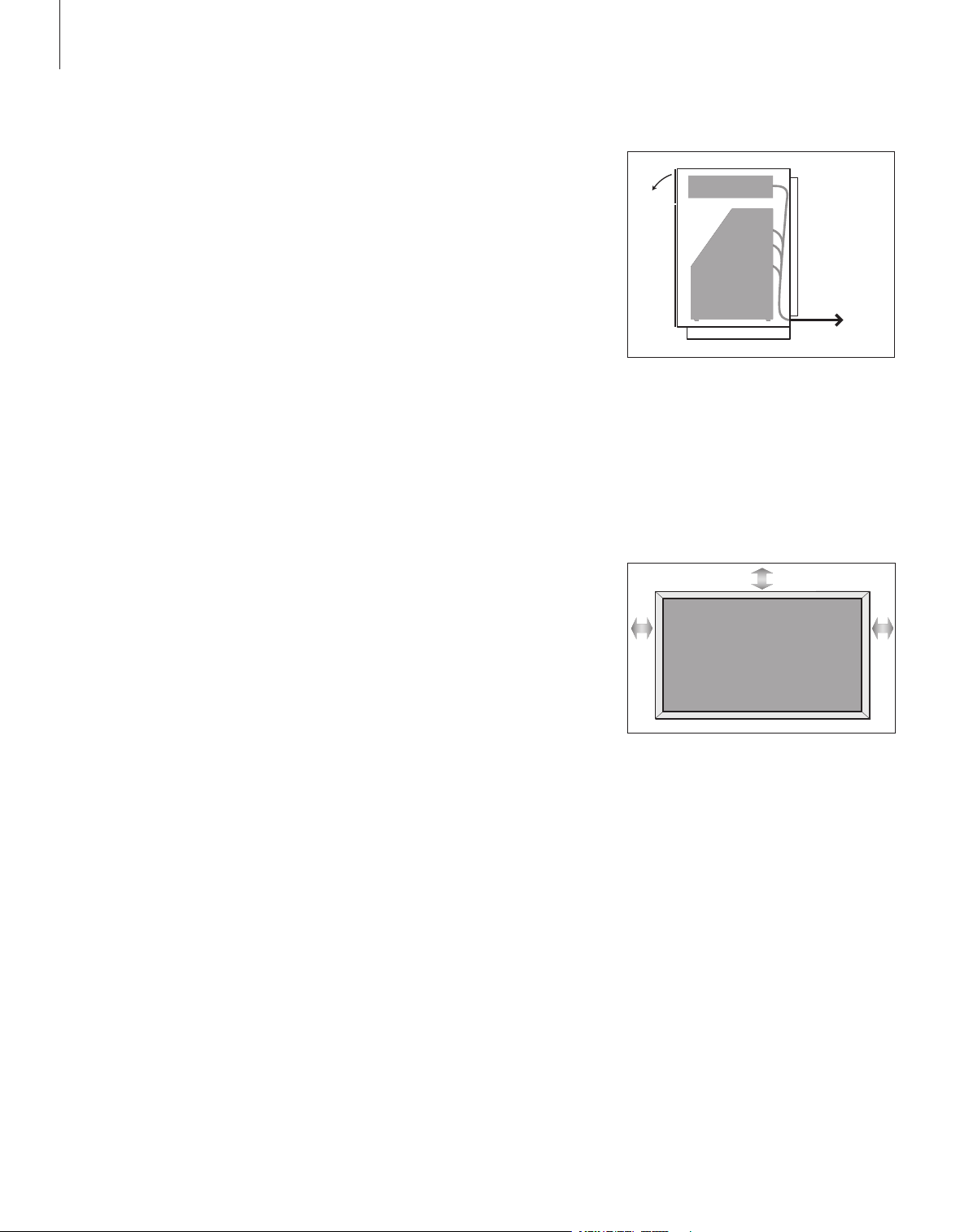
– When mounting the screen in the wall
bracket, leave a space of about 10
centimetres at the top, bot tom and sides.
Place BeoSystem 2 in the Cabinet. When
connections are complete, attach the back cover
with the four screws included with the Cabinet.
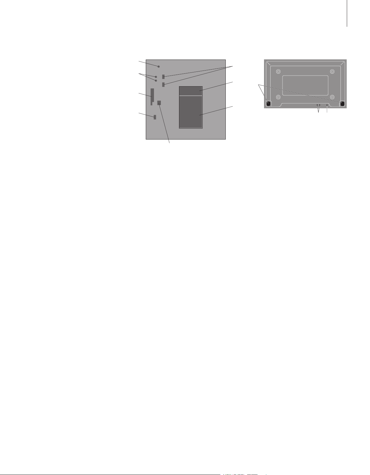
Overview of sockets
5
1
2
3
4
8
6
7
1
2
3
5
BeoSystem 2:
1 Mains switch
2 IR receiver sockets
3 Close -up socket panel
4 Mains connection
5 Plasma screen socket area
6 Speaker and digital input socket panel
7 AV and aerial socket panel
8 Fan socket
The plasma screen:
1 Speaker connection panels*
2 A / V connection panel
3 Mains connection
*When connecting external loudspeakers, connect
them to the loudspeaker sockets on BeoSystem 2
and not to the plasma screen!
For further information about the sockets, refer to
the chapter ‘Socket panels’ on page 9.
A
B C D
B B
B
C
C
D
D
6
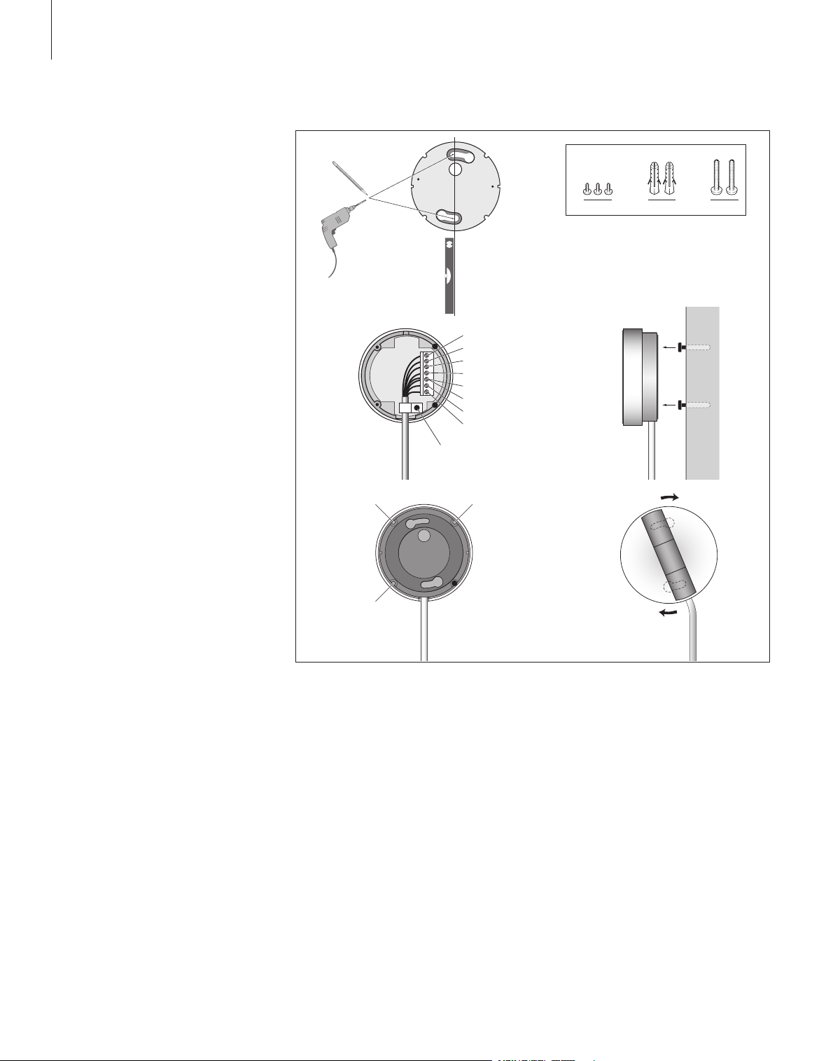
Mount and connect the IR receiver
To facilitate remote control operation of
BeoVision 4 and all connected equipment, you
must connect the IR receiver to BeoSystem 2.
The IR receiver is a kind of ‘eye’ which is
capable of receiving signals from your Beo4
remote control and sending them to
BeoSystem 2. BeoSystem 2 then sends the
appropriate control signals to your plasma
screen or other connected equipment.
>> Set up BeoVision 4 and BeoSystem 2
When mounting the IR receiver, make sure to
place the receiver on the same wall as the
screen. If the IR receiver is placed incorrectly,
the light emitted by the screen can impede
remote control operation of BeoVision 4!
When you have mounted the IR receiver as
shown on this page, connect it to the
IR IN socket on BeoSystem 2.
White
Blue
Green
Yellow
Black
Brown
Grey
Red
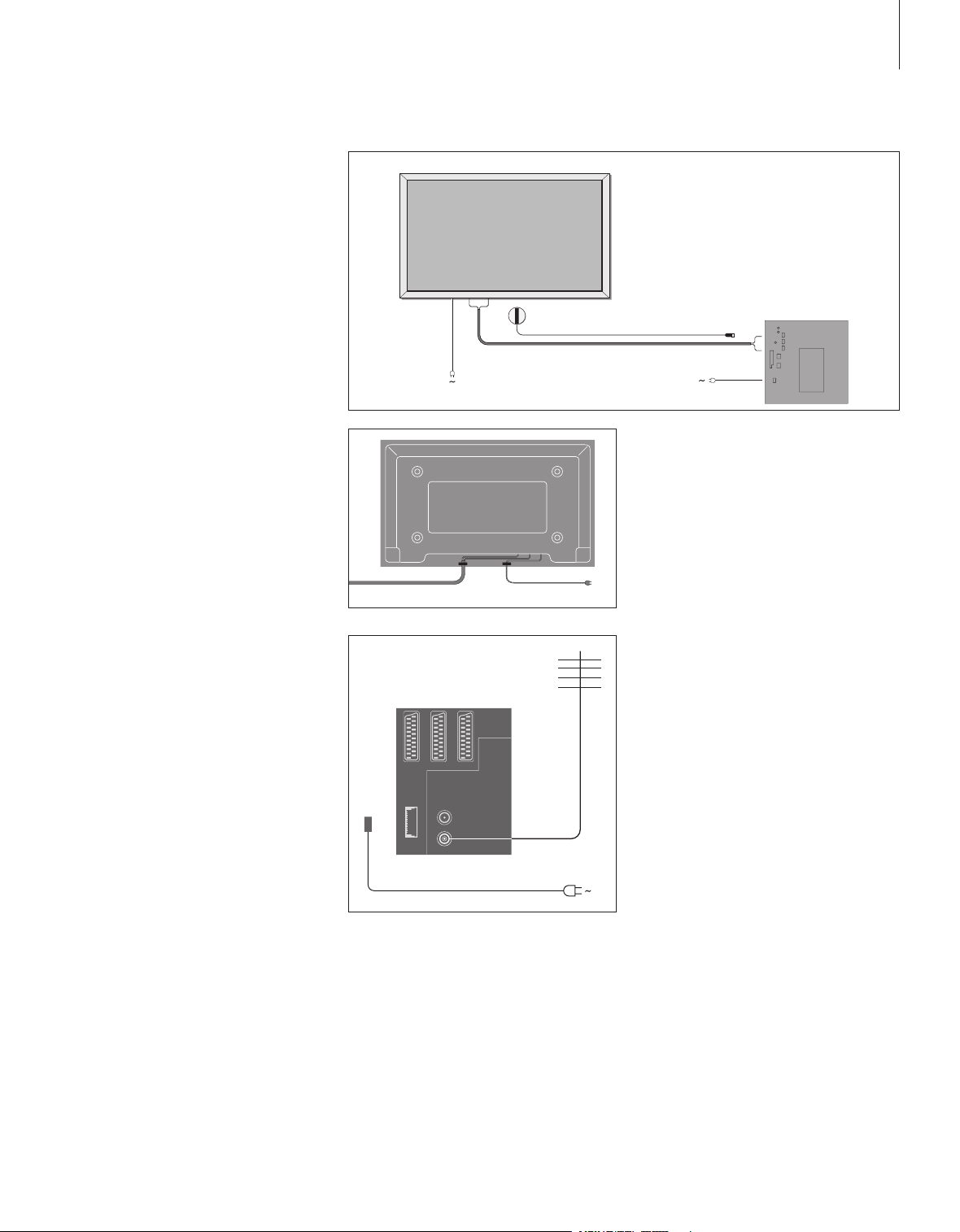
Connect the plasma screen
RGB
RS232
SERIAL
PC IN
IR-IN
*
BeoSystem 2
7
If longer cables are necessary, they are
available from your Bang & Olufsen retailer.
The two plugs at each end of the cable only
match specific sockets, so it is not possible to
connec t the cables incorrec tly if you follow
the procedure described below:
– Connect one 15-pin plug to the RGB socket on
BeoSystem 2 and the 9-pin plug at the same
end to the RS232 socket on BeoSystem 2.
– Connect the 15-pin plug at the opposite end to
the PC IN socket on the screen, and the 9-pin
plug at the same end to the SERIAL socket on
the screen.
– Connect the IR receiver to the appropriate IR-IN
socket on BeoSystem 2.
– Connect the two mains cords to the appropriate
sockets on BeoSystem 2 and the screen, but do
not connect them to the mains yet!
It is necessary to secure the mains cord in the
cable bands, as shown in the diagram. Otherwise,
the mains cord can be tugged free of the socket.
Aerial and mains connection
Make sure that BeoSystem 2 and the screen
are placed properly before connecting the
system.
> Connect the screen to the mains.
> Connect the aerial to the socket marked VHF/
UHF on BeoSystem 2.
> Connect BeoSystem 2 to the mains.
If you have not yet connected speakers, or you
wish to connect any other equipment to
BeoSystem 2, do not connect to the mains yet!
When connections are complete…
Switch on the mains switch on the back of
BeoSystem 2. The system is in standby mode and
ready to be used. You can now begin tuning in
channels, as explained in ‘Tune in TV channels’ on
page 26 in the Guide.
BeoVision 4 was designed to be left in standby
mode when not in use. Therefore, to facilitate
remote control operation, it is essential that you
leave the mains switch on.
1
2
3
1
2
8
Maintenance
Regular maintenance, such as
cleaning, is the responsibility of the
user. To achieve the best result,
follow the instructions to the right.
Contact your Bang & Olufsen retailer
to determine recommendations for
regular maintenance.
Cleaning surfaces…
Wipe dust off the surfaces using a dry, soft
cloth. Remove grease stains or persistent dir t
with a sof t, lint-free, firmly wrung cloth,
dipped in a solution of water containing only
a few drops of mild detergent, such as
washing-up liquid. These cleaning
instructions apply to any stand or wall
bracket as well.
About the plasma screen…
Clean only with a dry, soft cloth. Do not use
liquid cleaners or aerosol cleaners.
Do not allow still pictures to be displayed on
the screen for an ex tended period of time, as
this can cause a permanent after-image to
remain on the screen. Examples of still
pictures are logos, video games, computer
images, and images displayed in 4:3 picture
format.
Cleaning the Beo4 remote control
Wipe the Beo4 remote control with a soft,
lint-free, firmly wrung cloth.
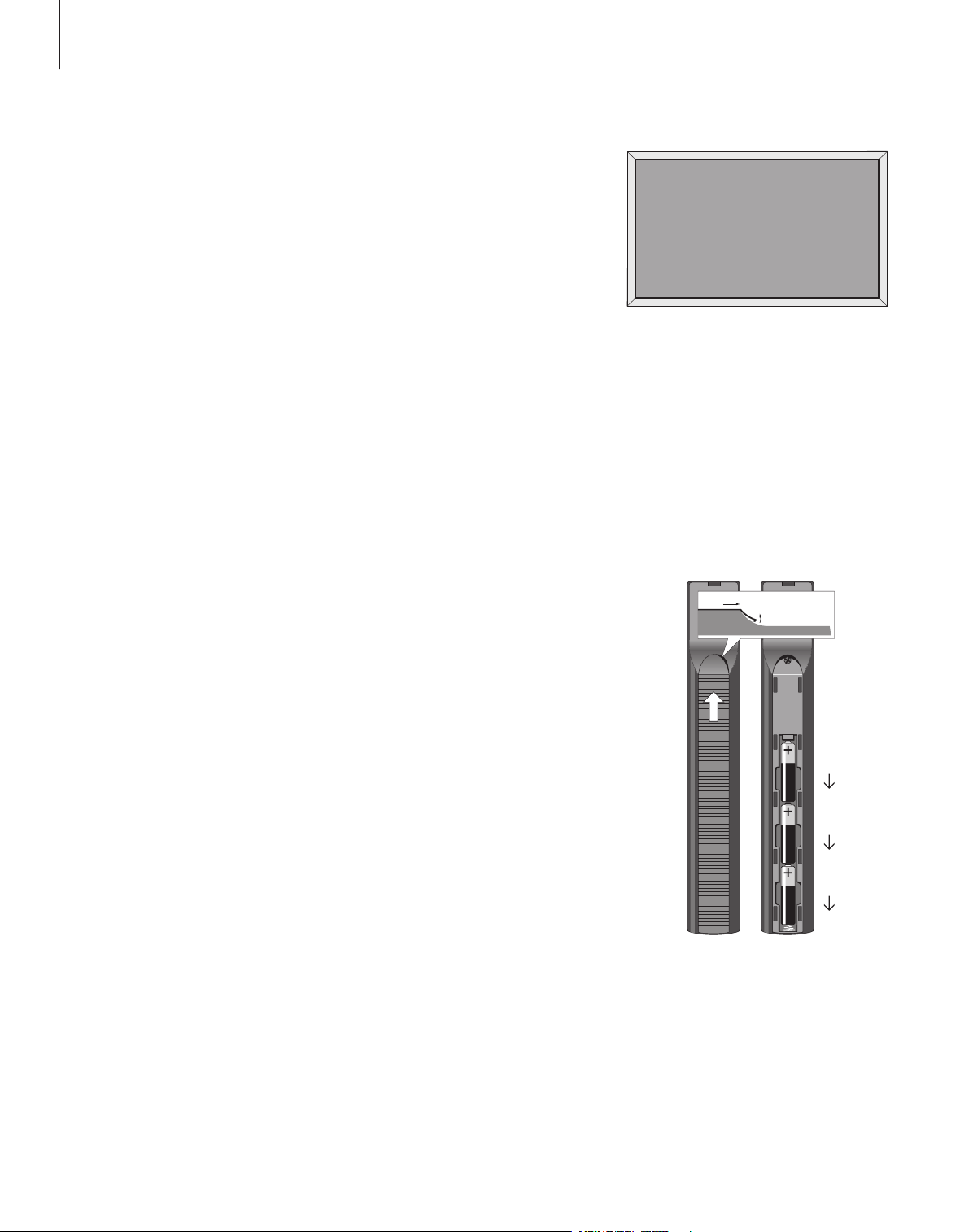
Changing the Beo4 batteries…
When ‘BATTERY’ appears in the Beo4 display,
it is time to change the batteries in the
remote control.
Never use alcohol or other solvents to clean any
part of BeoVision 4!
NOTE! If the front screen glass should crack or chip,
or if it should be damaged in any way, it must be
replaced immediately, as it could otherwise cause
injury. Please contact your Bang & Olufsen retailer.
The Beo4 requires three batteries. Use 1.5
volt (size AA A) Alkaline batteries only.
Replace the batteries as shown on this page.
Keep a finger on top of the batteries until the
lid is replaced.
When you have replaced the batteries, you
must wait for about 10 seconds until ‘TV ’
appears in the display. The Beo4 remote
control is then ready for use again.
Socket panels
DECOD ER
MASTE R
LINK
AVV.
TAPE
IR-OU T
VGA-I N
SPDIF
3
VHF/U HF
LINK
75 Ω
ATTN.
OFF ON
9
The socket panel on BeoSystem 2 allows
you to connect signal input cables as
well as a variety of extra equipment,
such as a DVD player or a linked Bang &
Olufsen audio system.
The V.TAPE, AV and DECODER sockets
are available for connection of extra
equipment.
Any equipment you connect to these
sockets must be registered in the
Connections menu. For further
information, refer to the chapter
‘Register and use additional video
equipment’ on page 32 in the Guide.
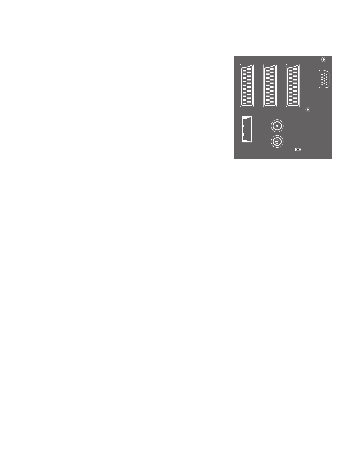
AV and aerial socket panel
V.TAPE
21-pin socket for the connection of a BeoCord
V 8000 video tape recorder.
AV
21-pin socket for the AV connection of other
equipment, such as a DVD player, set-top box or a
second decoder. Do not connect baseband
decoders here.
DECODER
21-pin socket for the connection of a secondary
set-top box or a primary decoder. The socket
provides the opportunity to connect either an AV
decoder or an RF decoder.
The socket may be used for an AV 2 Expander
instead, which gives the opportunity to connect a
decoder or other non-Bang & Olufsen auxiliary
video equipment at the same time.
MASTER LINK
Socket for connection of a compatible Bang &
Olufsen audio system.
The socket is also used for BeoLink distribution of
sound throughout the house.
AV and aerial socket panel.
LINK
Aerial output socket for distribution of video
signals to other rooms.
VHF/ UHF
Aerial input socket from your external aerial or
cable TV network.
ATTN. ON / OFF
Aerial signal attenuator. Options are:
OFF: Normal setting
ON: Signals damped
IR OUTPUT
For connection of a set-top box.
VGA-IN
Socket for connection of a High Definition video
source or a PC.
SPDIF 3
Digital input socket for connection of, for
example, a DVD player. SPDIF 3 is for digital input
from equipment connected to the VGA-IN socket
on BeoSystem 2.

REAR SUBWO OFER REAR
FRONT FRONT
CENTR E SPDIF
2
1
10
>> Socket panels
Speaker and digital input socket panel
FRONT
The two sockets are used for connecting the front
speakers in a surround sound setup.
CENTRE
Socket for connecting centre speakers in a
surround sound setup.
REAR
The two sockets are used for connecting the rear
speakers in a surround sound setup.
SUBWOOFER
Socket used for connecting a BeoLab 2 subwoofer
in a surround sound setup.
SPDIF 1
Digital input socket for connection of, for
example, a DVD player. SPDIF 1 is for digital input
from equipment connected to the AV socket on
BeoSystem 2.
SPDIF 2
Digital input socket for connection of, for
example, a DVD player. SPDIF 2 is for digital input
from equipment connected to the V.TAPE socket
on BeoSystem 2.
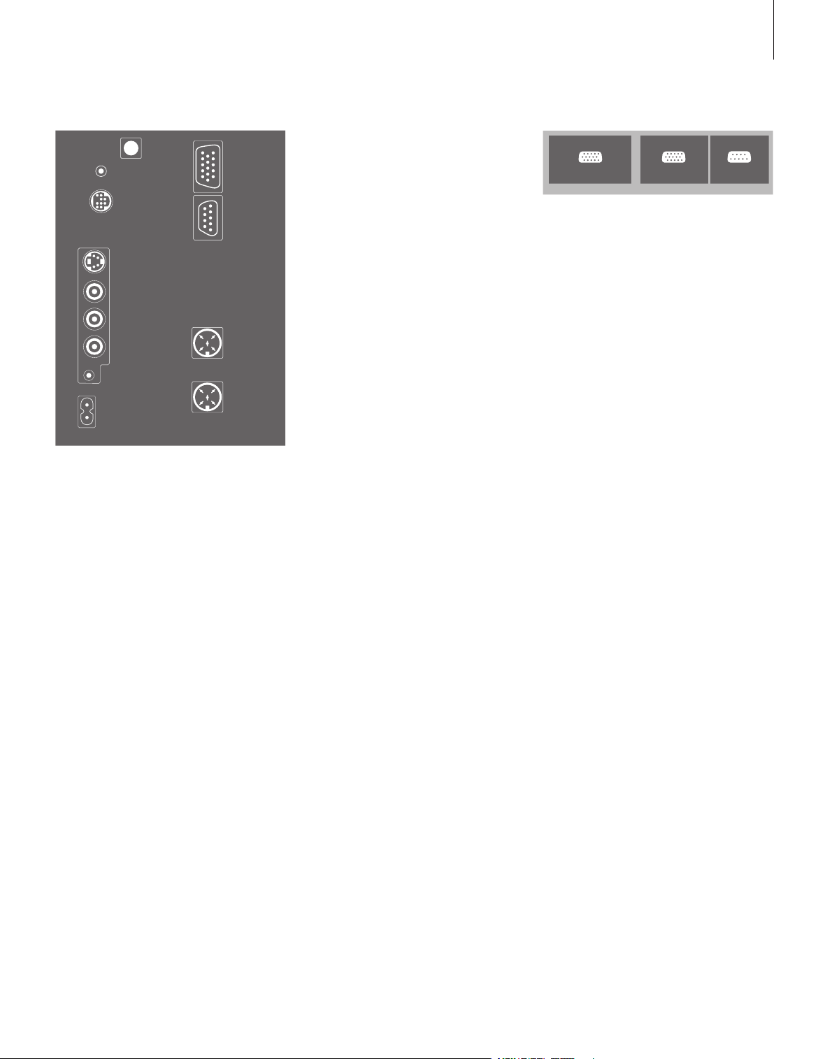
Additional sockets
ON/OFF
Mains switch.
IR IN
For connection of a BeoLink IR receiver enabling
remote control operation of BeoVision 4.
MAINS
Connection to the mains.
RGB
For connection of the screen.
RS232
For connection of the screen.
FAN
For connection of an external ventilator.
S-VHS / VIDEO / R / L / PHONES
The Camcorder and headphones sockets. For
more information, refer to the chapter ‘Close-up
socket panel on BeoSystem 2’ on page 12.
If the V.TAPE socket is set up for V.Mem or None,
the SPDIF 2 socket is dedicated to the equipment
connected to the DECODER socket instead.
Socket panel – plasma screen
DVI PC IN SERIAL
IR-IN
FAN
0/12 V CO NTRO L
MAINS
RGB
ON/OF F
RS232
PHONES
L
R
VIDEO
S-VHS
11
The socket panel on the back of the screen
contains sockets for connection to BeoSystem 2.
DVI
Socket for connection of a High Definition video
source or a PC.
PC IN
Socket for connection to the RGB socket on
BeoSystem 2.
SERIAL
Socket for connection to the RS232 socket on
BeoSystem 2.
For the installer…
When connections are complete, you must select
the screen type in a Service menu.
While BeoVision 4 is on…
> Press MENU to bring up the main menu.
p to highlight Setup and press GO.
> Press
0 twice, followed by GO. The Service
> Press
menu appears.
1 to bring up the Monitor menu.
> Press
p to highlight Plasma version setup, and
> Press
.
press GO
m or p to select the screen type and press
> Press
GO to store it.
> Press EXIT to leave the menu.
> Press • to switch off the system.
IMPORTANT! If you wish to connect a computer
to the screen and use the screen as a monitor,
make sure that BeoSystem 2, BeoVision 4, the
computer, and all equipment connected to the
computer are all disconnected from the mains
before you connect the computer and the screen
to each other. In addition, the computer must be
connected to a grounded wall outlet as specified
in the computer’s setting-up instructions.

PHONES
LRVIDEOS-VHS
12
Close-up socket panel on BeoSystem 2
You can connect headphones and
listen to a TV programme, or you can
connect a Camcorder and watch your
home movies on BeoVision 4. If you
have connected, for example, a
BeoCord V 8000 video tape recorder,
you can copy Camcorder recordings
onto a videotape.
The close-up socket panel
S-VHS
For the connection of S-VHS or Hi-8 Camcorders
only.
VIDEO – R – L
These sockets are for connection of a video
camera:
L – R: For audio connection (right and left
sound channel respectively).
VIDEO: For the Video signal.
PHONES
You can connect stereo headphones to the socket
marked PHONES. The speakers connected to
BeoSystem 2 can then be cut out by pressing the
middle of the Beo4 volume button.
Watch Camcorder on BeoVision 4
To watch your Camcorder recordings, connect
the Camcorder and switch BeoVision 4 on.
When you start playback on your Camcorder,
BeoSystem 2 automatically registers the
signal and you can see the pictures from the
Camcorder on BeoVision 4.
Copy from a Camcorder
If you have connected a video tape recorder,
such as a BeoCord V 8000, to BeoSystem 2,
and you connect your Camcorder to the
Camcorder and headphones sockets, you can
copy Camcorder recordings onto a videotape.
While the tape is being copied, you can watch
a TV programme or switch BeoSystem 2 to
standby.
To copy a recording from a Camcorder…
> Connect your Camcorder and star t playback on
the Camcorder.
> Press RECORD to prepare BeoCord V 8000 for
recording.
> Press RECORD again to start recording.
> Press V MEM and then STOP to pause a
recording.
> Press RECORD to resume a paused recording,
or…
> …press STOP again to stop a recording entirely.
If the signal from the Camcorder is switched
off…
> Press LIST repeatedly to display CAMERA on
Beo4 and press GO
In order to display CAMERA on Beo4, you must
first add it to the Beo4 list of functions. For further
information, refer to the chapter ‘Customise Beo4’
on page 32.
.
Loudspeaker setup – surround sound
13
A surround sound setup fits easily
into your living room. Let the picture
determine your ideal listening and
viewing position. You get the best
sound experience in the area created
by the speakers.
In a surround sound setup, you must
calibrate the speakers. To calibrate
means to set the balance between
speakers. Refer to the following
pages for further instruction.
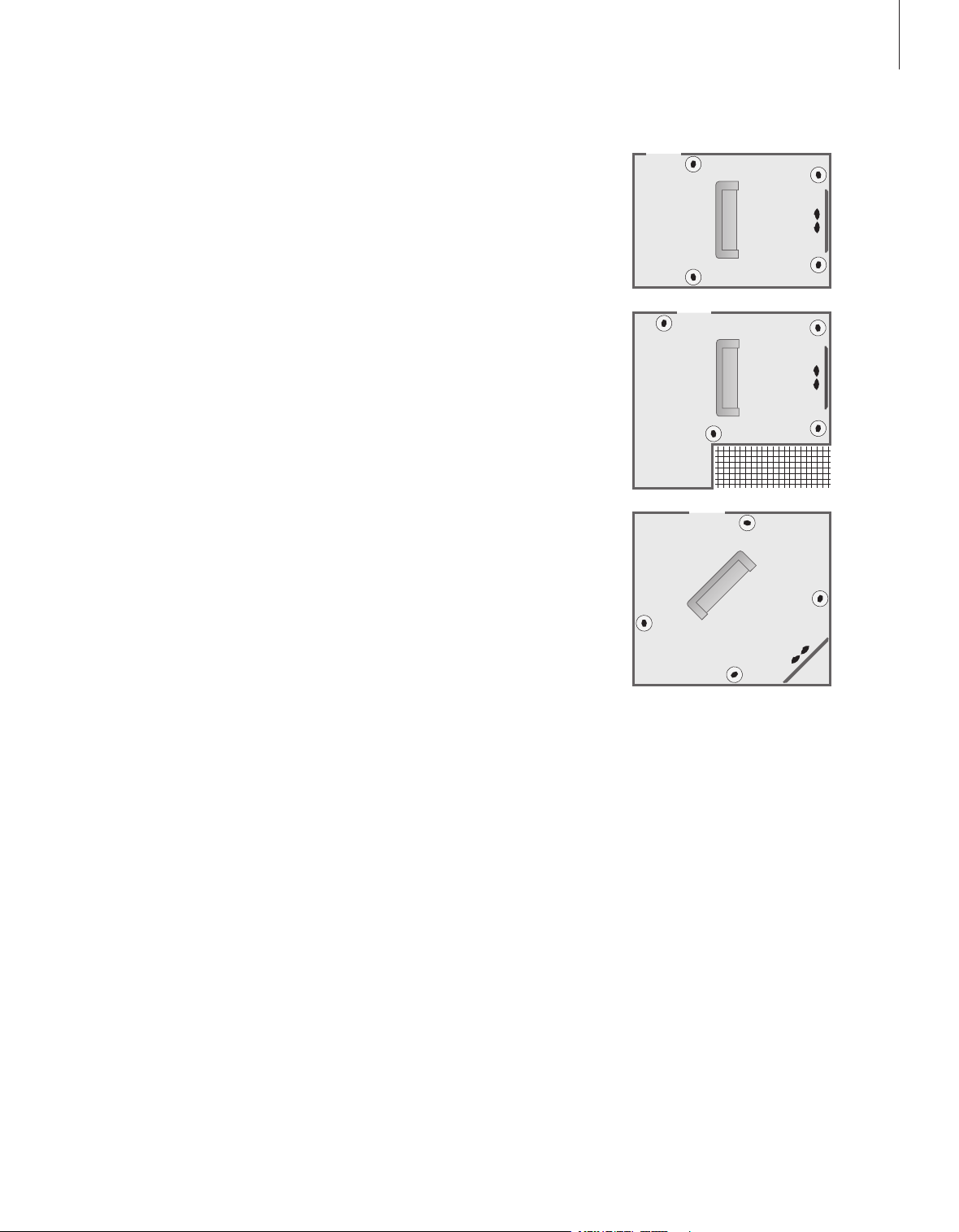
Place external speakers
The three illustrations to the right show
examples of BeoVision 4 and speakers placed
in various types and sizes of rooms.
The following guidelines apply for all
speaker setups:
– Always use your most powerful speakers as
your front speakers.
– Place your speakers where you want them
before you connec t them.
– The best placement for the rear speakers is
on either side behind your favourite
listening position.
– The front and rear sets of speakers do not
necessarily have to be placed in the corners
of the room.
– If you connect a BeoLab 2 subwoofer, refer
to the subwoofer’s own Guide for
information about placement possibilities.
FRONT
SUBWOOFER
REAR
CENTRE
L R
L R
BeoSystem 2
Sound
1 Adjustment
2 Sp eaker typ e
3 Speaker distance
4 Speaker level
5 Speaker mode
6 Sound syst em
Front Rear Subwoo fer
Beolab 1 Beolab 6000 Yes
14
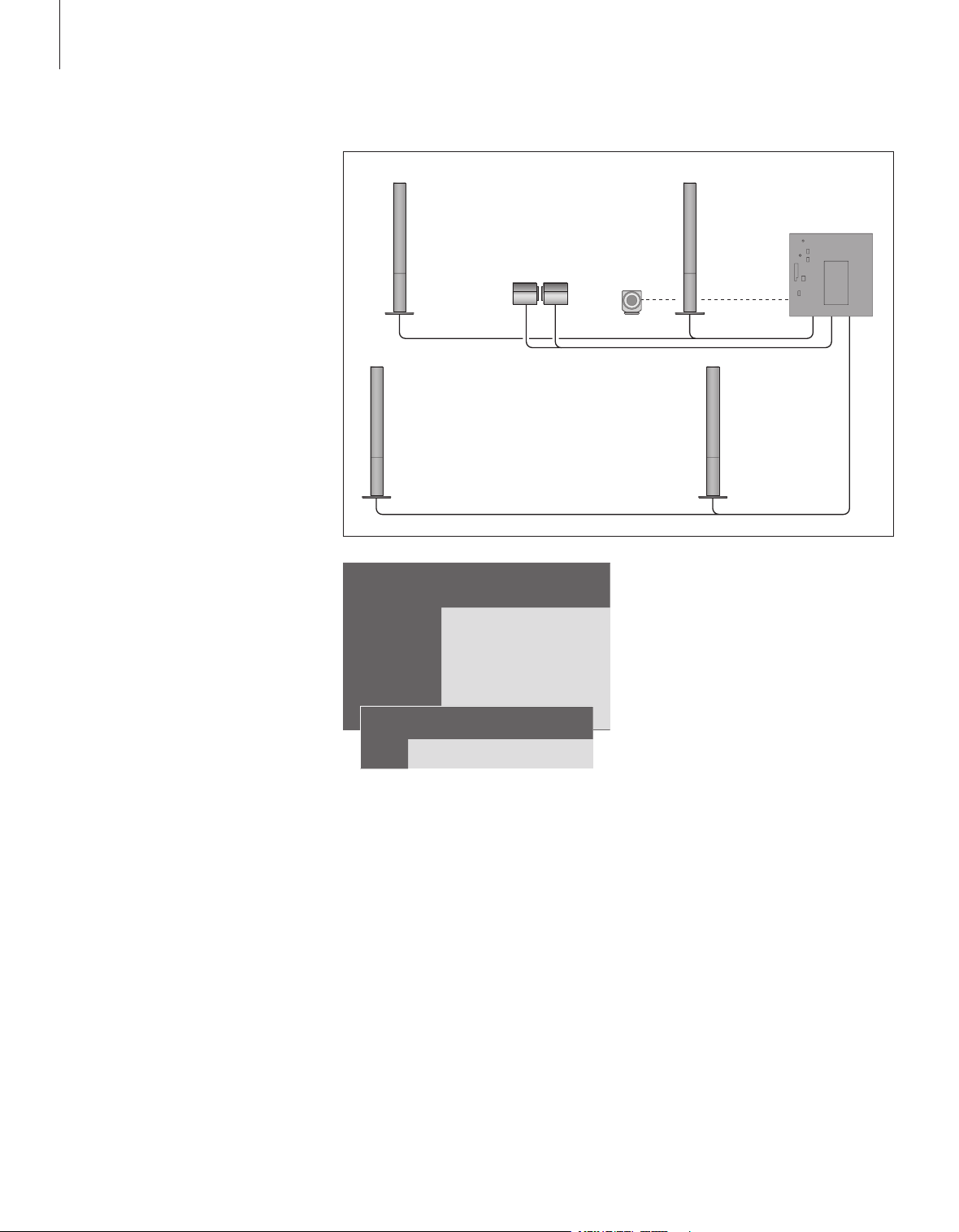
Connect speakers
You can connec t Bang & Olufsen speakers
and a BeoLab 2 subwoofer to BeoVision 4 via
the connection panel on the rear of
BeoSystem 2. The speakers must be Bang &
Olufsen Power Link speakers.
You can loop the signals through from
speaker to speaker (as described in the Guide
enclosed with your speakers) , or you can
connec t each individual speaker to a socket.
If necessary, longer cables and adaptors are
available from your Bang & Olufsen retailer.
Use the cables enclosed with the speakers to
make the following connections:
> Connect the two front speakers to the sockets
marked FRONT.
> Connect the two rear speakers to the sockets
marked REAR.
> Connect the centre speakers to the socket
marked CENTRE. Loop the signals through from
speaker to speaker when connecting the centre
speakers.
> Connect the subwoofer to the socket marked
SUBWOOFER.
Always remember to set the L – R – LINE switch on
both the front and rear sets of speakers to L or R
(left and right channel) to indicate their position in
each speaker set. Set the left front speaker to L,
the right rear speaker to R, and so on.
If you have only one set of speakers, connect
these to the sockets marked FRONT.
>> Loudspeaker setup – surround sound
> Press MENU to bring up the main menu.
3 to bring up the Setup menu.
> Press
2 to bring up the Sound menu.
> Press
2 again to bring up the Speaker type
> Press
menu.
p or m to reveal your speaker type
> Press
n to move on to the next speaker set.
and
Choose None if no speakers are connected.
> If you have a BeoLab 2 subwoofer, press
move the cursor to Subwoofer and press
change to Yes
.
n to
p to
> Press GO to store your choices, or…
> …press EXIT to leave the menu without storing.
If you have only one set of speakers, set ‘Front’ to
‘None’ – NOT to your speaker type!
For further information about the ‘Speaker type’
menu, refer to page 38.
Loading...