


P4V800D-X
User Guide
Motherboard

E2221
First Edition
August 2005
Copyright © 2005 ASUSTeK COMPUTER INC. All Rights Reserved.
No part of this manual, including the products and software described in it, may be reproduced, transmitted, transcribed, stored in a retrieval system, or translated into any language in any form or by any means, except documentation kept by the purchaser for backup purposes, without the express written permission of ASUSTeK COMPUTER INC. (“ ASUS”).
Product warranty or service will not be extended if: (1) the product is repaired, modified or altered, unless such repair, modification of alteration is authorized in writing by ASUS; or (2) the serial number of the product is defaced or missing.
ASUS PROVIDES THIS MANUAL “AS IS” WITHOUT WARRANTY OF ANY KIND, EITHER EXPRESS OR IMPLIED, INCLUDING BUT NOT LIMITED TO THE IMPLIED WARRANTIES OR CONDITIONS OF MERCHANTABILITY OR FITNESS FOR A PARTICULAR PURPOSE. IN NO EVENT SHALL ASUS, ITS DIRECTORS, OFFICERS, EMPLOYEES OR AGENTS BE LIABLE FOR ANY INDIRECT, SPECIAL, INCIDENTAL, OR CONSEQUENTIAL DAMAGES (INCLUDING DAMAGES FOR LOSS OF PROFITS, LOSS OF BUSINESS, LOSS OF USE OR DATA, INTERRUPTION OF BUSINESS AND THE LIKE), EVEN IF ASUS HAS BEEN ADVISED OF THE POSSIBILITY OF SUCH DAMAGES ARISING FROM ANY DEFECT OR ERROR IN THIS MANUAL OR PRODUCT.
SPECIFICATIONS AND INFORMATION CONTAINED IN THIS MANUAL ARE FURNISHED FOR INFORMATIONAL USE ONLY, AND ARE SUBJECT TO CHANGE AT ANY TIME WITHOUT NOTICE, AND SHOULD NOT BE CONSTRUED AS A COMMITMENT BY ASUS. ASUS ASSUMES NO RESPONSIBILITY OR LIABILITY FOR ANY ERRORS OR INACCURACIES THAT MAY APPEAR IN THIS MANUAL, INCLUDING THE PRODUCTS AND SOFTWARE DESCRIBED IN IT.
Products and corporate names appearing in this manual may or may not be registered trademarks or copyrights of their respective companies, and are used only for identification or explanation and to the ownersʼ benefit, without intent to infringe.
ii

Contents
Notices ........................................................................................................... |
v |
Safety Information.......................................................................................... |
vi |
About This Guide.......................................................................................... |
vii |
P4V800D-X Specifications Summary.......................................................... |
viii |
Chapter 1: |
Product Introduction |
|
|
1.1 |
Welcome! ....................................................................................... |
1-2 |
|
1.2 |
Package Contents.......................................................................... |
1-2 |
|
1.3 |
Special Features............................................................................ |
1-2 |
|
|
1.3.1 |
Product highlights ........................................................... |
1-2 |
|
1.3.2 |
Innovative ASUS features ............................................... |
1-4 |
1.4 |
Before You Proceed....................................................................... |
1-5 |
|
1.5 |
Motherboard Overview................................................................... |
1-6 |
|
|
1.5.1 |
Motherboard layout ......................................................... |
1-6 |
|
1.5.2 |
Placement direction ........................................................ |
1-7 |
|
1.5.3 |
Screw holes .................................................................... |
1-7 |
1.6 |
Central Processing Unit (CPU) ...................................................... |
1-8 |
|
|
1.6.1 |
Overview ......................................................................... |
1-8 |
|
1.6.2 |
Installing the CPU ........................................................... |
1-8 |
1.7 |
System Memory............................................................................. |
1-9 |
|
|
1.7.1 |
Overview ......................................................................... |
1-9 |
|
1.7.2 |
Memory configurations .................................................... |
1-9 |
|
1.7.3 |
Installing a DIMM ........................................................... |
1-11 |
|
1.7.4 |
Removing a DIMM ......................................................... |
1-11 |
1.8 |
Expansion Slots ........................................................................... |
1-12 |
|
|
1.8.1 |
Installing an expansion card ......................................... |
1-12 |
|
1.8.2 |
Configuring an expansion card ..................................... |
1-12 |
|
1.8.3 |
AGP slot ........................................................................ |
1-14 |
|
1.8.4 |
PCI slots ........................................................................ |
1-14 |
|
1.8.5 |
PCI Express x16 slot ...................................................... |
1-14 |
1.9 |
Jumpers |
....................................................................................... |
1-15 |
1.10 |
Connectors................................................................................... |
1-17 |
|
|
1.10.1 .................................................. |
Rear panel connectors |
1-17 |
|
1.10.2 ....................................................... |
Internal connectors |
1-18 |
Chapter 2: |
BIOS Setup |
|
|
2.1 |
Managing and Updating Your BIOS............................................... |
2-2 |
|
|
2.1.1 Creating a bootable floppy disk....................................... |
2-2 |
|
|
2.1.2 Using AFUDOS to copy the current BIOS....................... |
2-2 |
|
|
2.1.3 Using AFUDOS to update the BIOS ............................... |
2-3 |
|
|
2.1.4 Using ASUS EZ Flash to update the BIOS ..................... |
2-5 |
|
iii

Contents
2.2 |
BIOS Setup Program ..................................................................... |
2-6 |
|
|
2.2.1 |
BIOS menu screen.......................................................... |
2-7 |
|
2.2.2 |
Menu bar......................................................................... |
2-7 |
|
2.2.3 |
Navigation keys............................................................... |
2-7 |
|
2.2.4 |
Menu items ..................................................................... |
2-8 |
|
2.2.5 |
Sub-menu items.............................................................. |
2-8 |
|
2.2.6 |
Configuration fields ......................................................... |
2-8 |
|
2.2.7 |
Pop-up window ............................................................... |
2-8 |
|
2.2.8 |
Scroll bar......................................................................... |
2-8 |
|
2.2.9 |
General help ................................................................... |
2-8 |
2.3 |
Main Menu ..................................................................................... |
2-9 |
|
2.4 |
Advanced Menu........................................................................... |
2-12 |
|
|
2.4.1 |
JumperFree Configuration ............................................ |
2-12 |
|
2.4.2 |
USB Configuration ........................................................ |
2-13 |
|
2.4.3 |
CPU Configuration........................................................ |
2-14 |
|
2.4.4 |
Chipset.......................................................................... |
2-15 |
|
2.4.5 |
Onboard Devices Configuration.................................... |
2-18 |
|
2.4.6 |
PCIPnP ......................................................................... |
2-19 |
2.5 |
Power Menu................................................................................. |
2-20 |
|
|
2.5.1 |
APM Configuration........................................................ |
2-21 |
|
2.5.2 |
Hardware Monitor ......................................................... |
2-23 |
2.6 |
Boot Menu.................................................................................... |
2-24 |
|
|
2.6.1 |
Boot Device Priority ...................................................... |
2-24 |
|
2.6.2 |
Boot Settings Configuration .......................................... |
2-25 |
|
2.6.3 |
Security......................................................................... |
2-26 |
2.7 |
Exit Menu..................................................................................... |
2-28 |
|
Chapter 3: |
Software Support |
|
|
3.1 |
Installing An Operating System...................................................... |
3-2 |
|
3.2 |
Support CD Information ................................................................. |
3-2 |
|
|
3.2.1 |
Running the support CD ................................................. |
3-2 |
|
3.2.2 |
Drivers menu................................................................... |
3-3 |
|
3.2.3 |
Utilities menu .................................................................. |
3-3 |
|
3.2.4 |
Contacts menu................................................................ |
3-4 |
3.3 |
VIA RAID configurations................................................................. |
3-5 |
|
|
3.3.1 |
Installing hard disks ........................................................ |
3-5 |
|
3.3.2 |
VIA RAID configurations ................................................. |
3-6 |
3.3 |
Creating a RAID driver disk............................................................ |
3-9 |
|
iv
Notices
Federal Communications Commission Statement
This device complies with FCC Rules Part 15. Operation is subject to the following two conditions:
•This device may not cause harmful interference, and
•This device must accept any interference received including interference that may cause undesired operation.
This equipment has been tested and found to comply with the limits for a Class B digital device, pursuant to Part 15 of the FCC Rules. These limits are designed to provide reasonable protection against harmful interference in a residential installation. This equipment generates, uses and can radiate radio frequency energy and, if not installed and used in accordance with manufacturerʼ s instructions, may cause harmful interference to radio communications. However, there is no guarantee that interference will not occur in a particular installation. If this equipment does cause harmful interference to radio or television reception, which can be determined by turning the equipment off and on, the user is encouraged to try to correct the interference by one or more of the following measures:
•Reorient or relocate the receiving antenna.
•Increase the separation between the equipment and receiver.
•Connect the equipment to an outlet on a circuit different from that to which the receiver is connected.
•Consult the dealer or an experienced radio/TV technician for help.
The use of shielded cables for connection of the monitor to the graphics card is required to assure compliance with FCC regulations. Changes or modifications to this unit not expressly approved by the party responsible for compliance could void the userʼs authority to operate this equipment.
Canadian Department of Communications Statement
This digital apparatus does not exceed the Class B limits for radio noise emissions from digital apparatus set out in the Radio Interference Regulations of the Canadian Department of Communications.
This class B digital apparatus complies with Canadian ICES-003.
v

Safety Information
Electrical safety
•To prevent electrical shock hazard, disconnect the power cable from the electrical outlet before relocating the system.
•When adding or removing devices to or from the system, ensure that the power cables for the devices are unplugged before the signal cables are connected. If possible, disconnect all power cables from the existing system before you add a device.
•Before connecting or removing signal cables from the motherboard, ensure that all power cables are unplugged.
•Seek professional assistance before using an adapter or extension cord. These devices could interrupt the grounding circuit.
•Make sure that your power supply is set to the correct voltage in your area. If you are not sure about the voltage of the electrical outlet you are using, contact your local power company.
•If the power supply is broken, do not try to fix it by yourself. Contact a qualified service technician or your retailer.
Operation safety
•Before installing the motherboard and adding devices on it, carefully read all the manuals that came with the package.
•Before using the product, make sure all cables are correctly connected and the power cables are not damaged. If you detect any damage, contact your dealer immediately.
•To avoid short circuits, keep paper clips, screws, and staples away from connectors, slots, sockets and circuitry.
•Avoid dust, humidity, and temperature extremes. Do not place the product in any area where it may become wet.
•Place the product on a stable surface.
•If you encounter technical problems with the product, contact a qualified service technician or your retailer.
vi
About This Guide
How this guide is organized
This manual contains the following parts:
•Chapter 1: Product Introduction
This chapter describes the features of the motherboard and the new technology it supports. It also lists the hardware setup procedures that you have to perform when installing system components. It includes description of the jumpers and connectors on the motherboard.
•Chapter 2: BIOS Information
This chapter tells how to change system settings through the BIOS Setup menus. Detailed descriptions of the BIOS parameters are also provided.
•Chapter 3: Software Support
This chapter describes the contents of the support CD that comes with the motherboard package.
Conventions used in this guide
To make sure that you perform certain tasks properly, take note of the following symbols used throughout this guide.
WARNING: Information to prevent injury to yourself when trying to complete a task.
CAUTION: Information to prevent damage to the components when trying to complete a task.
IMPORTANT: Information that you MUST follow to complete a task. NOTE: Tips and additional information to aid in completing a task.
Where to find more information
Refer to the following sources for additional information and for product and software updates.
1.ASUS websites
The ASUS websites worldwide provide updated information on ASUS hardware and software products. Refer to the ASUS contact information.
2.Optional documentation
Your product package may include optional documentation, such as warranty flyers, that may have been added by your dealer. These documents are not part of the standard package.
vii

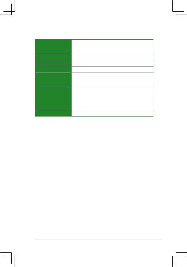
P4V800D-X Specifications Summary
CPU
Chipset
FrontSideBus(FSB)
Memory
Expansion Slots
Storage
Audio
LAN
USB
Special features
Back panel I/O ports
Socket478forIntelPentium4/Celeronupto3.4GHz+
IntelHyper-ThreadingTechnologyready
VIA PT880 Ultra
VIA VT8237R PLUS
800/533/400 MHz
Dual Channel Memory Architecture
4 x 184-pin DIMM Sockets for up to 4GB, support PC3200/ PC2700/PC2100, non-ECC DDR SDRAM memory
1 x AGP 8X
1 x PCI Express x16 (x4 mode only)
3 x PCI
2 x UltraDMA 133/100/66/33
2 x Serial ATA with RAID 0, 1 and JBOD function
ADI AD1888 SoundMAX 6-channel audio CODEC Support S/PDIF out interface
Realtek 10/100 Mbps Ethernet LAN
Supports up to eight USB 2.0 ports
Wake on Ring, LAN, USB, Keyboard & Mouse STR (Suspend-to-RAM)
STD (Suspend-to-Disk) S/PDIF out interface
ASUS C.P.R. (CPU Parameter Recall) ASUS MyLogo
ASUS EZ Flash
ASUS CrashFree BIOS 2
1 x Parallel port
1 x Serial (COM2) port
1 x PS/2 Keyboard port (purple)
1 x PS/2 Mouse port (green)
1 x Audio I/O port
1 x S/PDIF Out (Coaxial) port
1 x LAN (RJ-45) port
4 x USB 2.0 ports
Internal I/O connectors |
2 x USB 2.0 connectors support additional 4 USB 2..0 ports |
|
|
CPU/Chassis FAN connectors |
|
|
Front panel audio connector |
|
|
CD/AUX audio in connectors |
|
|
20-pin ATX power connector |
|
|
4-pin ATX 12V power connector |
|
|
20-pin panel connector |
|
|
(continued next page) |
|
viii
P4V800D-X Specifications Summary
BIOS features
Industry standard
Manageability
Power Requirement
Support CD
Accessary
Form factor
4 Mb Flash ROM, AMI BIOS, PnP, DMI2.0, WfM2.0, SM BIOS 2.3, ACPI, ASUS EZ Flash, ASUS CrashFree BIOS 2, C.P.R. MyLogo
PCI 2.2, USB 2.0/1.1
WfM 2.0, DMI 2.0, WOL by PME, WOR by PME
ATX power supply (with 4-pin 12V plug)
Drivers
ASUS PC Probe
Anti-Virus Software (OEM Version)
Userʼs Manual
1 x UltraDMA 133/100/66 cable
1 x SATA cable
1 x SATA power cable
1 x FDD cable I/O shield
ATX Form Factor, 12” x 8.2” (30.5cm x 20.8cm)
* Note: The specifications are subject to change without notice.
ix
x
This chapter describes the motherboard features and the new technologies it supports.
Product1
Introduction

1.1Welcome!
Thank you for buying an ASUS® P4V800D-X motherboard!
The motherboard delivers a host of new features and latest technologies, making it another standout in the long line of ASUS quality motherboards!
Before you start installing the motherboard, and hardware devices on it, check the items in your package with the list below.
1.2Package contents
Check your motherboard package for the following items.
Motherboard |
ASUS P4V800D-X motherboard |
Cables |
1 x Ultra 133/100/66 DMA cable |
|
1 x Serial ATA cable |
|
1 x Serial ATA power cable |
|
1 x Floppy Disk Drive cable |
Accessories |
I/O shield |
Application CDs |
ASUS motherboard support CD |
Documentation |
User guide |
If any of the above items is damaged or missing, contact your retailer.
1.3Special features
1.3.1Product highlights
Dual-Channel DDR 400 
The 128-bit TwinBank DDR Memory architecture doubles the DDR 400 (PC3200) bandwidth. System bottlenecks are eliminated with balanced architecture and peak bandwidths up to 6.4 GB/s. See page 1-9 for details.
Serial ATA technology 
Serial ATA is the next generation ATA specification that provides scalable performance for today and tomorrow. With up to 150MB/s data transfer rate, Serial ATA is faster than current Parallel ATA, while providing 100% software compatibility. P4V800D-X supports RAID 0, RAID 1 and JBOD. See page 1-19 for details.
1-2 |
Chapter 1: Product Introduction |
Integrated 10/100 LAN controller 
A 10/100Mbps Fast Ethernet controller is embedded in this motherboard to give you a fast and reliable connection to a local area network (LAN) and the Internet.
Coaxial S/PDIF out 
This motherboard provides convenient connectivity to external home theater audio systems via an coaxial S/PDIF-out (SONY-PHILIPS Digital Interface) jack. it allows to transfer digital audio without converting to analog format and keeps the best signal quality. See page 1-17 for details.
USB 2.0 technology 
USB 2.0 is the latest connectivity standard for next generation components and peripherals. Backwards compatible with current USB 1.1 peripherals, USB 2.0 delivers transfer speeds up to 40 times faster at 480 MB/s, for easy connectivity and ultra-fast data transfer rate. See pages1-17 & 1-20 for details.
AGP8X
AGP8X (AGP 3.0) is the mainstream VGA interface specification that enables enhanced graphics performance with high bandwidth up to 2.13 GB/s. See page 1-14 for details.
PCI Express Interface 
The motherboard fully supports PCI Express, the latest I/O interconnect technology that speeds up the PCI bus. PCI Express features point-to-point serial interconnections between devices and allows higher clockspeeds by carrying data in packets. This high speed interface is software compatible with existing PCI specifications.
ASUS P4V800D-X Motherboard |
1-3 |
1.3.2Innovative ASUS features
ASUS CrashFree BIOS 2 
The CrashFree BIOS2 feature now includes the BIOS auto-recovery function in a support CD. Users can reboot their system through the support CD when a bootable disk is not available, and go through the simple BIOS auto-recovery process. ASUS motherboards now enable users to enjoy this protection feature without the need to pay for an optional ROM.
ASUS EZ Flash BIOS 
With ASUS EZ Flash, you can update BIOS before entering operating system. No more DOS-based flash utility and bootable diskette required. See page 2-6 for details.
C.P.R. (CPU Parameter Recall)
When the system hangs due to overclocking failure, there is no need to open the case to clear CMOS data. Just simply restart the system, the BIOS would show the previous setting and then users can amend the CPU setting again.
ASUS MyLogo™ 
This new feature present in the motherboard allows you to personalize and add style to your system with customizable boot logos.
1-4 |
Chapter 1: Product Introduction |

1.4Before you proceed
Take note of the following precautions before you install motherboard components or change any motherboard settings.
•Unplug the power cord from the wall socket before touching any
component.
•Use a grounded wrist strap or touch a safely grounded object or a metal object, such as the power supply case, before handling components to avoid damaging them due to static electricity
•Hold components by the edges to avoid touching the ICs on them.
•Whenever you uninstall any component, place it on a grounded antistatic pad or in the bag that came with the component.
•Before you install or remove any component, ensure that the ATX power supply is switched off or the power cord is detached from the power supply. Failure to do so may cause severe damage to the motherboard, peripherals, and/or components.
Onboard LED
The motherboard comes with a standby power LED that lights up to indicate that the system is ON, in sleep mode, or in soft-off mode. This is a reminder that you should shut down the system and unplug the power cable before removing or plugging in any motherboard component. The illustration below shows the location of the onboard LED.
P4V800D-X |
|
|
|
SB_PWR |
|
|
ON |
OFF |
P4V800D-X Onboard LED |
Standby |
Powered |
Power |
Off |
|
ASUS P4V800D-X Motherboard |
1-5 |

1.5Motherboard overview
1.5.1Motherboard layout
|
|
20.8cm (8.2in) |
|
|
|
|
|
|
|
|
PS/2KBMS |
|
|
|
|
|
|
|
|
|
|
T: Mouse |
|
|
ATX12V |
|
|
|
|
|
|
|
B: Keyboard |
|
|
|
|
|
|
|
|
|
|
|
KBPWR |
|
|
|
|
|
|
|
|
|
SPDIF1 |
|
|
|
module) |
module) |
module) |
module) |
|
|
|
PARALLELPORT |
478 |
CPU_FAN |
|
|
|
|||||
COM1 |
USBPW1 |
Socket |
|
bit,184(641ADIMM -pin |
bit,184(642ADIMM -pin |
bit,184(641BDIMM -pin |
bit,184(642BDIMM -pin |
|
|
ATXPWR |
|
|
|
|
|
|
|
|
|
|
|
USB12 |
|
|
|
|
|
|
|
|
|
|
Bottom: |
Top: |
VIA |
|
DDR |
DDR |
DDR |
DDR |
|
PRI IDE |
(12.0in) |
Below:Mic In |
|
|
|
|||||||
USB3 RJ-45 |
|
|
|
|
|
|
|
|
||
USB4 |
|
PT880 |
|
|
|
|
|
|
|
|
Top:Line In |
|
Ultra |
|
|
|
|
|
|
|
|
|
|
|
|
|
|
|
|
|
|
|
Center:Line Out |
|
|
|
|
|
|
|
|
|
|
|
RTL |
P4V800D-X |
|
|
|
|
|
|
|
30.5cm |
|
|
|
|
|
|
|
|
|
|
|
|
8201CL |
AGP |
|
|
|
|
|
SEC IDE |
|
|
|
|
|
|
|
|
|
|
|||
CD AUX |
|
|
|
|
|
|
|
|
||
|
FP_AUDIO |
|
|
|
|
|
|
|
|
|
|
|
PCIEX16 |
|
|
|
VIA |
|
|
|
|
AD1888 |
|
|
VT8237R+ |
|
|
|
|
|||
|
|
|
|
|
|
|
|
|
||
|
|
|
|
® |
|
|
|
|
|
|
|
|
PCI1 |
CR2032 3V |
|
|
SATA2 |
|
|
||
|
|
|
Lithium Cell |
|
|
|
|
|
|
|
|
|
|
CMOS Power |
|
|
SATA1 |
|
|
||
Super |
PCI2 |
|
|
|
4Mb |
FAN |
|
|
||
I/O |
|
|
|
PWR_ |
|
CHAFAN |
||||
|
|
|
|
LPC |
|
|||||
|
|
|
|
|
|
|
|
|
||
|
|
PCI3 |
|
USBPW2 |
SB_PWR |
|
|
|||
|
|
|
|
|
|
|
|
|||
|
|
|
|
|
|
|
|
|
||
|
|
|
USB56 |
USB78 |
|
CLRTC |
PANEL |
|||
|
|
|
|
|
|
|||||
|
GAME |
|
FLOPPY |
|
|
|
|
|
|
|
1-6 |
Chapter 1: Product Introduction |
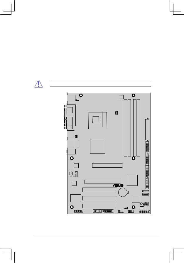
1.5.2Placement direction
When installing the motherboard, make sure that you place it into the chassis in the correct orientation. The edge with external ports goes to the rear part of the chassis as indicated in the image below.
1.5.3Screw holes
Place six screws into the holes indicated by circles to secure the motherboard to the chassis.
Do not overtighten the screws! Doing so can damage the motherboard.
Place this side towards-- the rear of the chassis
P4V800D-X |
® |
ASUS P4V800D-X Motherboard |
1-7 |
1.6Central Processing Unit (CPU)
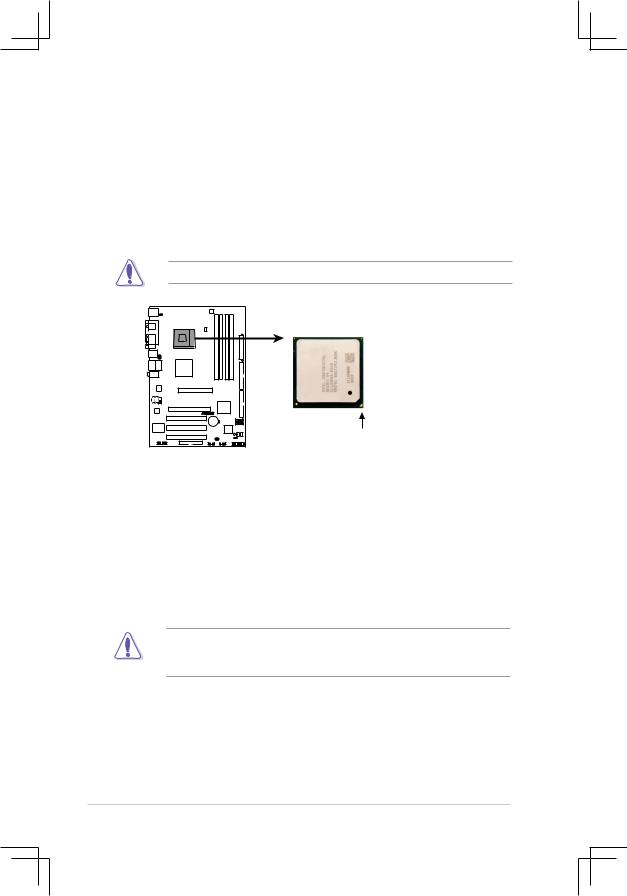
1.6.1Overview
The motherboard has a Socket 478 for installation. The Intel Pentium 4 / Celeron CPU has a “marked” corner. This corner is usually indicated with a notch, and/or a golden square or triangle. Refer to this indicator when orienting the CPU. A fan and heat sink should be installed on top of the CPU to prevent overheating.
Do not use processors with core speeds of less than 1GHz.
P4V800D-X
Gold Arrow
P4V800D-X Socket 478
1.6.2Installing the CPU
Follow these steps to install a CPU:
1.Locate the CPU socket. Open the socket by pulling the lever gently sideways away from the socket, then lift the lever upwards to a 90 to 100-degree angle.
2.Insert the CPU with the correct orientation. The notched or golden corner of the CPU must be oriented toward the inner corner of the socket base nearest to the lever hinge.
The CPU should drop easily into place. Do not force the CPU into the socket to avoid bending the pins. If the CPU does not fit, check its alignment and look for bent pins.
1-8 |
Chapter 1: Product Introduction |
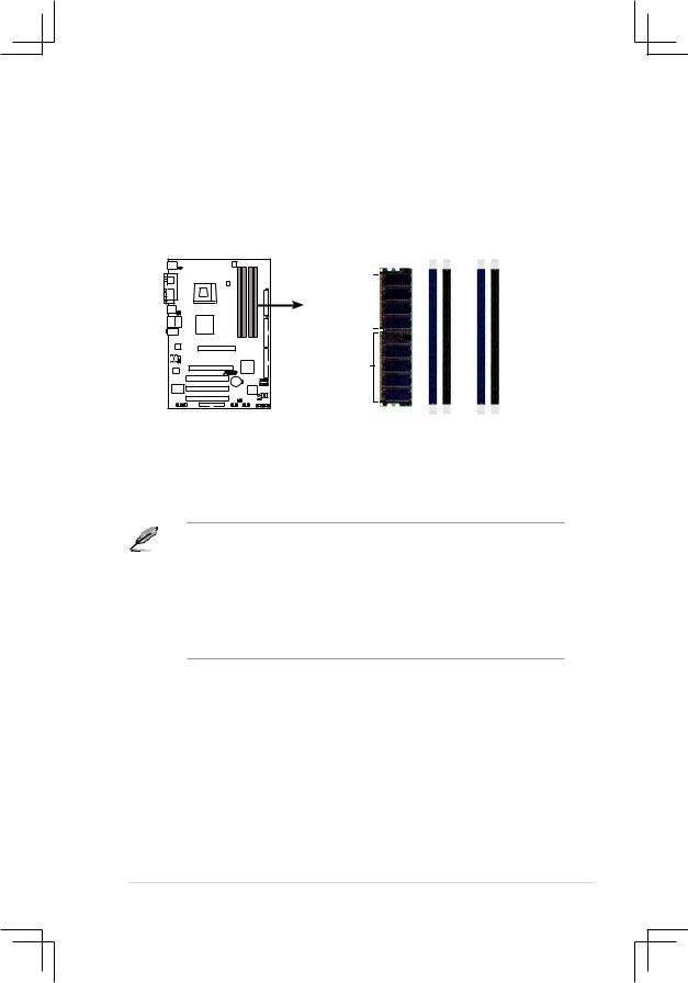
1.7System memory
1.7.1Overview
The motherboard has four Double Data Rate (DDR) DIMM sockets that support up to 4 GB unbuffered non-ECC DDR400/333/266 DDR SDRAM DIMMs.
Pins80
P4V800D-X
Pins104
P4V800D-X 184-Pin DDR DIMM Sockets
DIMM A1 |
DIMM A2 |
DIMM B1 |
DIMM B2 |
1.7.2Memory configurations
You may install single or double-sided 64 MB, 128 MB, 256 MB, 512 MB, and 1 GB DDR DIMMs to the sockets.
1.DIMMs with more than 8 devices on each side of the module are not supported.
2.Make sure the memory frequency and bus frequency setting in the BIOS are the same or set to [Auto] ensure system stability.
3.A DDR DIMM is keyed with a notch so that it fits in only one direction. DO NOT force a DIMM into a socket to avoid damaging the DIMM.
4.For optimum compatibility, it is recommended that you obtain memory modules from qualified vendors. See the next page for a list of qualified DIMM vendors.
5.Visit ASUS website (www.asus.com) for latest Qualified Vendor List.
ASUS P4V800D-X Motherboard |
1-9 |

Qualified Vendors List
|
Size |
Vendor |
Model |
CL |
Brand |
SS/DS |
Component |
|
256MB |
Kingston |
KVR333X64C25/256 |
N/A |
Kingston |
SS |
D3208DH1T-6 |
|
256MB |
Kingston |
KVR333X64C25/256 |
N/A |
Hynix |
DS |
HY5DU56822BT-D43 |
|
512MB |
Kingston |
KVR333X64C25/512 |
N/A |
Kingston |
DS |
D3208DH1T-6 |
|
512MB |
Kingston |
KVR400X64C3A/512 |
N/A |
Hynix |
DS |
HY5DU56822BT-D43 |
|
512MB |
Kingston |
KVR400X64C3A/512 |
N/A |
Kingston |
SS |
HY5DU12822BT-D43 |
|
256MB |
Kingston |
KVR400X64C3A/256 |
N/A |
Hynix |
SS |
HY5DU56822BT-D43 |
|
256MB |
Kingston |
KVR400X64C3A/256 |
N/A |
Kingston |
SS |
D3208DL3T-5A |
|
256MB |
Kingston |
KVR400X64C3A/256 |
N/A |
PSC |
SS |
A2S56D30BTP |
|
1G |
Kingston |
KVR400X64C3A/1G |
N/A |
Infineon |
DS |
HYB25D512800BE-5B |
|
256MB |
Infineon |
HYS64D32300GU-5-C |
|
Infineon |
SS |
HYB25D256800CE-5C |
|
512MB |
Infineon |
HYS64D64320GU-5-C |
|
Infineon |
SS |
HYB25D512800BE-5B |
|
512MB |
Infineon |
HYS64D64320GU-5-C |
|
Infineon |
DS |
HYB25D256800CE-5C |
|
256MB |
Infineon |
HYS64D32300GU-5-C |
N/A |
Infineon |
SS |
HYB25D256800CE-5C |
|
512MB |
Infineon |
HYS64D64320GU-6-C |
N/A |
Infineon |
DS |
HYB25D256800CE-6C |
|
256MB |
HY |
HYMD232646D8J-D43 |
N/A |
Hynix |
SS |
HY5DU56822BT-D43 |
|
512MB |
HY |
HYMD264646D8J-D43 |
N/A |
Hynix |
DS |
HY5DU56822BT-D43 |
|
256MB |
HY |
HYMD232646B8J-J |
N/A |
Hynix |
SS |
HY5DU56822BT-J |
|
512MB |
HY |
HYMD264646B8J-J |
N/A |
Hynix |
DS |
HY5DU56822BT-J |
|
256MB |
Corsair |
VS256MB400 |
N/A |
Value select |
SS |
VS32M8-5 2B0409 |
|
256MB |
Corsair |
XMS3202v3.1 |
|
Infineon |
SS |
HYB25D256807BT-5B |
|
512MB |
Corsair |
XMS3205v1.2 |
N/A |
Winbond |
DS |
W942508CH-5 |
|
512MB |
Corsair |
VS512MB400 |
N/A |
Value select |
DS |
VS32M8-5 2B0402 |
|
256MB |
Corsair |
VS256MB333 |
N/A |
Samsung |
SS |
K4H5608380-TCB3 |
|
512MB |
Corsair |
XMS2702v3.1 |
|
Mosel |
DS |
V58C2256804SAT6 |
|
512MB |
Micron |
MT16VDDT6464AG-335GB |
N/A |
Micron |
DS |
MT46V32M8TG-6TG |
|
256MB |
Micron |
MT8VDDT3264AG-335GB |
|
Micron |
SS |
MT46V32M8TG-6TG |
|
256MB |
Micron |
MT8VDDT3264AG-40BGB |
|
Micron |
SS |
MT46V32M8TG-5BG |
|
512MB |
Micron |
MT16VDDT6464AG-40BCB |
|
Micron |
DS |
MT46V32M8TG-5BC |
|
256MB |
Samsung |
M368L3223FTN-CCC |
|
Samsung |
SS |
K4H560838F-TCCC |
|
512MB |
Samsung |
M368L6423FTN-CCC |
|
Samsung |
DS |
K4H560838F-TCCC |
|
256MB |
Samsung |
M368L3223FTN-CB3 |
|
Samsung |
SS |
K4H560838F-TCB3 |
|
512MB |
Samsung |
M368L6423FTN-CB3 |
|
Samsung |
DS |
K4H560838F-TCB3 |
|
256MB |
Winbond |
U24256ADWBG6H20 |
N/A |
Winbond |
SS |
W942508CH-5 |
|
512MB |
Winbond |
DDR333-512 |
N/A |
Winbond |
DS |
W942508BH-6 |
|
256MB |
Transcend |
DDR400-256 |
N/A |
Samsung |
SS |
K4H560838F-TCCC |
|
512MB |
Transcend |
DDR400-512 |
N/A |
Mosel |
DS |
V58C2256804SAT5B |
|
256MB |
Pmi |
3208GATA07-04A7 |
N/A |
Pmi |
SS |
PM4D328D50406EU |
|
256MB |
Kingmax |
MPXB62D-38KT3R |
N/A |
Kingmax |
SS |
KDL388P4LA-50 |
|
256MB |
Nanya |
NT256D64S88B1G-5T |
|
Nanya |
SS |
NT5DS32M8BT-5T |
|
512MB |
Apacer |
77.90728.U1G |
|
Apacer |
DS |
AM3A568AJT-6B |
|
256MB |
Smart |
U24256ADSRG6H20 |
N/A |
Smart |
SS |
D32M8XS60HBX4AMV |
|
512MB |
BiaoXing |
BXXC22D-38KT3B |
N/A |
BiaoXing |
DS |
VM256D328BT-5 |
|
|
|
|
|
|
|
|
A*: Supports one module inserted in any slot as Single-channel memory configuration
B*: Supports one pair of modules inserted into either the blue slots or the black slots as one pair of Dual-channel memory configuration
C*: Supports 4 modules inserted into both the blue and black slots as two pairs of Dual-channel memory configuration
1-10 |
Chapter 1: Product Introduction |
1.7.3Installing a DIMM
Make sure to unplug the power supply before adding or removing DIMMs or other system components. Failure to do so may cause severe damage to both the motherboard and the components.
Follow these steps to install a DIMM.
1.Locate the DIMM sockets in the motherboard.
2.Unlock a DIMM socket by pressing the retaining clips outward.
3.Align a DIMM on the socket such that the notch on the DIMM matches the break on the socket.
DDR DIMM notch
Unlocked Retaining
Clip
A DDR DIMM is keyed with a notch so that it fits in only one direction. DO NOT force a DIMM into a socket to avoid damaging the DIMM.
4.Firmly insert the DIMM into the socket until the retaining clips snap back in place and the DIMM is properly seated.
Locked Retaining Clip
1.7.4Removing a DIMM
Follow these steps to remove a DIMM.
1.Simultaneously press the retaining clips outward to unlock the DIMM.
Support the DIMM lightly with your fingers when pressing the retaining clips. The DIMM might get damaged when it flips out with extra force.
2.Remove the DIMM from the socket.
ASUS P4V800D-X Motherboard |
1-11 |
 Loading...