


P4SP-MX
User Guide
Motherboard

E1530
First Edition V1
January 2004
Copyright © 2004 ASUSTeK COMPUTER INC. All Rights Reserved.
No part of this manual, including the products and software described in it, may be reproduced, transmitted, transcribed, stored in a retrieval system, or translated into any language in any form or by any means, except documentation kept by the purchaser for backup purposes, without the express written permission of ASUSTeK COMPUTER INC. (“ASUS”).
Product warranty or service will not be extended if: (1) the product is repaired, modified or altered, unless such repair, modification of alteration is authorized in writing by ASUS; or (2) the serial number of the product is defaced or missing.
ASUS PROVIDES THIS MANUAL “AS IS” WITHOUT WARRANTY OF ANY KIND, EITHER EXPRESS OR IMPLIED, INCLUDING BUT NOT LIMITED TO THE IMPLIED WARRANTIES OR CONDITIONS OF MERCHANTABILITY OR FITNESS FOR A PARTICULAR PURPOSE. IN NO EVENT SHALL ASUS, ITS DIRECTORS, OFFICERS, EMPLOYEES OR AGENTS BE LIABLE FOR ANY INDIRECT, SPECIAL, INCIDENTAL, OR CONSEQUENTIAL DAMAGES (INCLUDING DAMAGES FOR LOSS OF PROFITS, LOSS OF BUSINESS, LOSS OF USE OR DATA, INTERRUPTION OF BUSINESS AND THE LIKE), EVEN IF ASUS HAS BEEN ADVISED OF THE POSSIBILITY OF SUCH DAMAGES ARISING FROM ANY DEFECT OR ERROR IN THIS MANUAL OR PRODUCT.
SPECIFICATIONS AND INFORMATION CONTAINED IN THIS MANUAL ARE FURNISHED FOR INFORMATIONAL USE ONLY, AND ARE SUBJECT TO CHANGE AT ANY TIME WITHOUT NOTICE, AND SHOULD NOT BE CONSTRUED AS A COMMITMENT BY ASUS. ASUS ASSUMES NO RESPONSIBILITY OR LIABILITY FOR ANY ERRORS OR INACCURACIES THAT MAY APPEAR IN THIS MANUAL, INCLUDING THE PRODUCTS AND SOFTWARE DESCRIBED IN IT.
Products and corporate names appearing in this manual may or may not be registered trademarks or copyrights of their respective companies, and are used only for identification or explanation and to the owners’ benefit, without intent to infringe.
ii

Contents
Notices ............................................................................................ |
v |
Safety information .......................................................................... |
vi |
P4SP-MX specification summary .................................................. |
vii |
About this guide ............................................................................ |
viii |
Chapter |
1: Product introduction |
|
|
1.1 |
Welcome! ........................................................................... |
1-2 |
|
1.2 |
Package contents ............................................................... |
1-2 |
|
1.3 |
Special features.................................................................. |
1-2 |
|
|
1.3.1 |
Product highlights .................................................. |
1-2 |
|
1.3.2 |
ASUS unique features ........................................... |
1-4 |
1.4 |
Before you proceed ............................................................ |
1-5 |
|
1.5 |
Motherboard overview ........................................................ |
1-6 |
|
|
1.5.1 |
Motherboard layout ................................................ |
1-6 |
|
1.5.2 |
Placement direction ............................................... |
1-7 |
|
1.5.3 |
Screw holes ........................................................... |
1-7 |
1.6 |
Central Processing Unit (CPU)........................................... |
1-8 |
|
|
1.6.1 |
Overview ................................................................ |
1-8 |
|
1.6.2 |
Installing the CPU .................................................. |
1-9 |
1.7 |
System memory ............................................................... |
1-10 |
|
|
1.7.1 |
DIMM sockets location ......................................... |
1-10 |
|
1.7.2 |
Memory configurations ........................................ |
1-10 |
|
1.7.3 |
Installing a DIMM .................................................. |
1-11 |
|
1.7.4 |
Removing a DIMM ................................................ |
1-11 |
1.8 |
Expansion slots ................................................................ |
1-12 |
|
|
1.8.1 |
Installing an expansion card ................................ |
1-12 |
|
1.8.2 |
Configuring an expansion card ............................ |
1-12 |
|
1.8.3 |
PCI slots .............................................................. |
1-14 |
|
1.8.4 |
AGP slot ............................................................... |
1-14 |
1.9 |
Jumpers............................................................................ |
1-15 |
|
1.10 |
Connectors ....................................................................... |
1-17 |
|
|
1.10.1 |
Rear panel connectors ......................................... |
1-17 |
|
1.10.2 |
Internal connectors .............................................. |
1-18 |
iii

Contents
Chapter 2: BIOS information
2.1 |
Managing and updating your BIOS .................................... |
2-2 |
|
|
2.1.1 Creating a bootable floppy disk ............................. |
2-2 |
|
|
2.1.2 Using ASUS EZ Flash to update the BIOS ............ |
2-3 |
|
|
2.1.3 |
Using the AFLASH utility ........................................ |
2-4 |
|
2.1.4 Recovering the BIOS with CrashFree BIOS .......... |
2-6 |
|
|
2.1.5 |
ASUS Update ........................................................ |
2-7 |
2.2 |
BIOS Setup program .......................................................... |
2-9 |
|
|
2.2.1 |
BIOS menu bar ...................................................... |
2-9 |
|
2.2.2 |
Legend bar ........................................................... |
2-10 |
2.3 |
Main menu ......................................................................... |
2-11 |
|
|
2.3.1 Primary and Secondary Master/Slave ................. |
2-13 |
|
|
2.3.2 |
Keyboard Features .............................................. |
2-15 |
2.4 |
Advanced menu ............................................................... |
2-16 |
|
|
2.4.1 |
Chip Configuration ............................................... |
2-18 |
|
2.4.2 |
I/O Device Configuration ...................................... |
2-20 |
|
2.4.3 |
PCI Configuration ................................................ |
2-21 |
2.5 |
Power menu ..................................................................... |
2-23 |
|
|
2.5.1 |
Power Up Control ................................................ |
2-24 |
|
2.5.2 |
Hardware Monitor ................................................ |
2-25 |
2.6 |
Boot menu ........................................................................ |
2-26 |
|
2.7 |
Exit menu ......................................................................... |
2-28 |
|
Chapter 3: Software support
3.1 |
Install an operating system ................................................. |
3-2 |
|
3.2 |
Support CD information ...................................................... |
3-2 |
|
|
3.2.1 |
Running the support CD ........................................ |
3-2 |
|
3.2.2 |
Installation items .................................................... |
3-3 |
iv

Notices
Federal Communications Commission Statement
This device complies with FCC Rules Part 15. Operation is subject to the following two conditions:
•This device may not cause harmful interference, and
•This device must accept any interference received including interference that may cause undesired operation.
This equipment has been tested and found to comply with the limits for a Class B digital device, pursuant to Part 15 of the FCC Rules. These limits are designed to provide reasonable protection against harmful interference in a residential installation. This equipment generates, uses and can radiate radio frequency energy and, if not installed and used in accordance with manufacturer’s instructions, may cause harmful interference to radio communications. However, there is no guarantee that interference will not occur in a particular installation. If this equipment does cause harmful interference to radio or television reception, which can be determined by turning the equipment off and on, the user is encouraged to try to correct the interference by one or more of the following measures:
•Reorient or relocate the receiving antenna.
•Increase the separation between the equipment and receiver.
•Connect the equipment to an outlet on a circuit different from that to which the receiver is connected.
•Consult the dealer or an experienced radio/TV technician for help.
The use of shielded cables for connection of the monitor to the graphics card is required to assure compliance with FCC regulations. Changes or modifications to this unit not expressly approved by the party responsible for compliance could void the user’s authority to operate this equipment.
Canadian Department of Communications Statement
This digital apparatus does not exceed the Class B limits for radio noise emissions from digital apparatus set out in the Radio Interference Regulations of the Canadian Department of Communications.
This class B digital apparatus complies with Canadian ICES-003.
v

Safety information
Electrical safety
•To prevent electrical shock hazard, disconnect the power cable from the electrical outlet before relocating the system.
•When adding or removing devices to or from the system, ensure that the power cables for the devices are unplugged before the signal cables are connected. If possible, disconnect all power cables from the existing system before you add a device.
•Before connecting or removing signal cables from the motherboard, ensure that all power cables are unplugged.
•Seek professional assistance before using an adpater or extension cord. These devices could interrupt the grounding circuit.
•Make sure that your power supply is set to the correct voltage in your area. If you are not sure about the voltage of the electrical outlet you are using, contact your local power company.
•If the power supply is broken, do not try to fix it by yourself. Contact a qualified service technician or your retailer.
Operation safety
•Before installing the motherboard and adding devices on it, carefully read all the manuals that came with the package.
•Before using the product, make sure all cables are correctly connected and the power cables are not damaged. If you detect any damage, contact your dealer immediately.
•To avoid short circuits, keep paper clips, screws, and staples away from connectors, slots, sockets and circuitry.
•Avoid dust, humidity, and temperature extremes. Do not place the product in any area where it may become wet.
•Place the product on a stable surface.
•If you encounter technical problems with the product, contact a qualified service technician or your retailer.
vi

P4SP-MX specification summary*
CPU |
Socket 478 for Intel® Pentium® 4/Celeron processor |
|
Intel® Hyper-Threading technology ready |
|
New power design for next generation Intel® Prescott CPU |
Chipset |
|
SiS651 Northbridge |
|
|
SiS962L Southbridge |
Front Side Bus (FSB) |
|
533/400MHz |
|
Memory |
|
2 x 184-pin DDR DIMM sockets for up to 2GB memory |
|
|
Supports PC2700/2100/1600 unbuffered non-ECC DDR |
|
DIMMs. |
Expansion slots |
|
1 x AGP 4X (1.5V only) |
|
|
3 x PCI |
VGA |
|
Integrated 3D graphics controller in SiS 651 chip |
|
Storage |
|
2 x UltraDMA133, PIO Mode 0 ~ 4 |
|
Audio |
|
ADI AD1888 6-channel audio CODEC |
|
LAN |
|
SiS962L integrated 10/100 Mbps Fast Ethernet with Realtek |
|
|
external PHY |
Special features |
|
Power loss restart |
|
|
Digital audio via an S/PDIF out inteface |
Rear panel I/O |
|
1 x Parallel port |
|
|
1 x S/PDIF out port |
|
1 x Video port |
|
1 x PS/2 keyboard port |
|
1 x PS/2 mouse port |
|
1 x RJ-45 port |
|
4 x USB 2.0/USB 1.1 ports |
|
Line In/Line Out/Microphone ports |
Internal I/O |
|
USB 2.0 connector for two additional USB ports |
|
|
CPU and chassis fan connectors |
|
20-pin/4-pin ATX 12V power connectors |
|
CD/AUX audio connectors |
|
GAME/MIDI connector |
|
Front panel audio connector |
|
Serial (COM1) connector |
|
Panel connector |
BIOS features |
|
2Mb Flash ROM, DMI 2.0, Award BIOS. TCAV PnP features, |
|
|
SM BIOS 2.3, WfM 2.0, ASUS CrashFree BIOS, ASUS EZ |
|
Flash |
|
|
* Specifications are subject to change without notice.
(Continued on the next page.)
vii
P4SP-MX specification summary
Industry standard
Manageability
Form Factor
Support CD contents
PCI 2.2, USB 2.0/1.1
WOL/WOR by PME, DMI 2.0, WfM 2.0
Micro-ATX form factor: 9.6 in x 9.6 in (24.5 cm x 24.5 cm)
Device drivers ASUS PC Probe ASUS LiveUpdate ASUS Screensaver
Adobe Acrobat Reader
Trend Micro™ PC-cillin 2002 anti-virus software Microsoft® DirectX 8.1
About this guide
Conventions used in this guide
To make sure that you perform certain tasks properly, take note of the following symbols used throughout this guide.
WARNING: Information to prevent injury to yourself when trying to complete a task.
CAUTION: Information to prevent damage to the components when trying to complete a task.
IMPORTANT: Information that you MUST follow to complete a task.
NOTE: Tips and additional information to aid in completing a task.
viii

Chapter 1
This chapter describes the features of the motherboard. It includes brief descriptions of the motherboard components, and illustrations of the layout, jumper settings, and connectors.
Product introduction
1.1Welcome!
Thank you for buying the ASUS® P4SP-MX motherboard!
The ASUS P4SP-MX motherboard delivers a host of new features and latest technologies making it another standout in the long line of ASUS quality motherboards!
Before you start installing the motherboard, and hardware devices on it, check the items in your package with the list below.
1.2Package contents
Check your P4SP-MX package for the following items.
ASUS P4SP-MX motherboard
Micro-ATX form factor: 9.6 in x 9.6 in (24.5 cm x 24.5 cm)
ASUS P4SP-MX series support CD
9-pin COM cable
80-conductor UltraDMA cable
Ribbon cable for a 3.5-inch floppy drive
I/O shield
Bag of extra jumper caps
User Guide
If any of the above items is damaged or missing, contact your retailer.
1.3Special features
1.3.1 Product highlights
Intel® Prescott CPU support
The motherboard comes with a 478-pin surface mount, Zero Insertion Force (ZIF) socket for the Intel® Pentium® 4 processor and 512/256KB L2 cache on 0.13 micron process. This motherboard supports 533/400 MHz system front side bus that allows 4.3GB/s and 3.2GB/s data transfer rates, respectively. The P4SP-MX also supports the next-generation Intel® Prescott CPU and the Intel® Hyper-Threading Technology. See page 1-8.
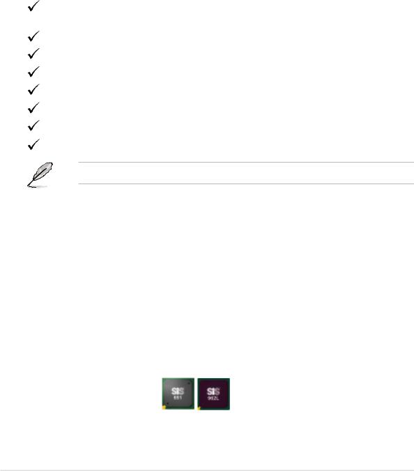
SiS651/962L chipset
Embedded in this motherboard is the SiS651/962L chipset that integrates various SiS-developed technologies to ensure an efficient and reliable computing performance.
1-2 |
Chapter 1: Product introduction |
The SiS651 Northbridge chip is a high performance Host Memory Controller for the Intel® Pentium® 4 processor, and supports a 2D/3D graphic engine, memory controller, AGP 4X, and 533MHz front side bus. The SiS651 interconnects with the SiS962L Southbridge chip at speeds of up to 1GB/s using the proprietary SiS MuTIOL® technology.
Providing I/O and peripheral support is the SiS962L MuTIOL® Media I/O. The Southbridge is a subsystem that integrates various I/O functions including dual-channel DMA133 bus master IDE, USB 2.0/1.1, Ethernet, and audio controllers. The SiS962L provides the necessary interfaces for the LPC, AC’97 audio/modem devices, and complies with the Advanced Power Management (APM) 1.2 and ACPI 1.0b specification.
Integrated 2D/3D graphic engine 
Embedded in the Northbridge is an integrated graphic engine with a 256-bit 3D and 2D graphics accelerator with maximum 64MB shared display memory.
See page 2-19.
Integrated 10/100 Mbps LAN controller
The SiS651 Northbridge provides an integrated Fast Ethernet solution that fully supports 10BASE-T/100BASE-TX networking. The integrated controller works with the onboard Realtek LAN PHY to give you faster Internet and LAN connections.
See page 1-17.
SoundMAX digital audio system
The SoundMax Digital Audio System is the industry’s highest performance and most reliable audio solution for business professionals, audiophiles, musicians, and gamers. SoundMAX Digital Audio System can output 5.1 channel surround and features state-of-the-art DLS2 MIDI synthesizer with Yamaha DLSbyXG sound set, 5.1 Virtual Theater™ and supports all major game audio technologies including Microsoft DirectX™8.0, Microsoft DirectSound 3D™, A3D, MacroFX, ZoomFX, MultiDrive 5.1 and EAX. See page 1-17.
USB 2.0 connectivity 
The motherboard rear panel is equipped with four (4) Universal Serial Bus (USB) ports to connect USB 2.0 devices. A USB header is also available at mid-board to accommodate a USB module for two (2) additional USB ports. The USB ports and header comply with USB 2.0 specification that supports up to 480 Mbps connection speed. This speed advantage over the conventional USB 1.1 (12 Mbps) allows faster Internet connection, interactive gaming, and simultaneous running of high-speed peripherals. USB 2.0 is backward compatible with USB 1.1.
See pages 1-17 and 1-20.
ASUS P4SP-MX motherboard user guide |
1-3 |

1.3.2 ASUS unique features
ASUS CrashFree BIOS 
CrashFree BIOS allows users to restore BIOS data from a floppy diskette even when BIOS code and data are corrupted during upgrade or invaded by a virus. Unlike other competing vendors’ products, ASUS motherboards now enable users to enjoy this protection feature without the need to pay for an optional ROM.
See page 2-6.
ASUS EZ Flash BIOS
With the ASUS EZ Flash, you can easily update the system BIOS even before loading the operating system. No need to use a DOS-based utility or boot from a floppy disk. See page 2-3.
1-4 |
Chapter 1: Product introduction |
1.4Before you proceed
Take note of the following precautions before you install motherboard components or change any motherboard settings.
• Unplug the power cord from the wall socket before touching any component.
•Use a grounded wrist strap or touch a safely grounded object or to a metal object, such as the power supply case, before handling components to avoid damaging them due to static electricity.
•Hold components by the edges to avoid touching the ICs on them.
•Whenever you uninstall any component, place it on a grounded antistatic pad or in the bag that came with the component.
•Before you install or remove any component, ensure that the ATX power supply is switched off or the power cord is detached from the power supply. Failure to do so may cause severe damage to the motherboard, peripherals, and/or components.
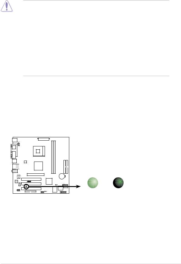
Onboard LED
The motherboard comes with a stand-by power LED. When lit, the green LED indicates that the system is ON, in sleep mode, or in soft-off mode, a reminder that you should shut down the system and unplug the power cable before removing or plugging in any motherboard component. The illustration below shows the location of the onboard LED.
P4SP-MX |
ON |
SB_PWR1
OFF
P4SP-MX Onboard LED |
Standby |
Powered |
Power |
Off |
ASUS P4SP-MX motherboard user guide |
1-5 |
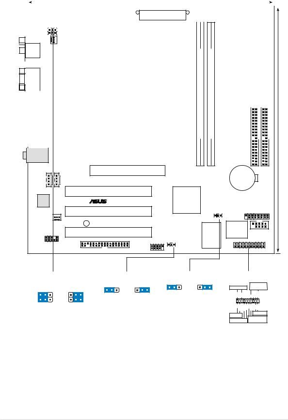
1.5Motherboard overview
1.5.1 |
|
|
|
|
Motherboard layout |
|
|
|
|
|
|
|
|
|
|
||||||||||||
|
|
|
|
|
|
|
|
|
|
|
|
|
24.4cm (9.6in) |
|
|
|
|
|
|
|
|
|
|
||||
|
|
|
|
|
|
|
|
|
|
|
|
|
|
|
|
|
|
|
|
|
|
|
|
|
|
|
|
|
|
|
|
|
|
|
|
|
|
|
|
|
|
|
|
|
|
|
|
|
|
|
|
|
|
|
|
|
|
|
|
|
|
|
|
|
|
|
|
|
|
|
|
|
|
|
|
|
|
|
|
|
|
|
|
|
|
|
|
|
|
|
|
|
|
|
|
|
|
ATX Power Connector |
|
|
|
|
|
|
|
|
|
|
|||
|
PS/2KBMS |
|
|
|
|
|
|
|
|
|
|
|
|
|
|
|
|
|
|
||||||||
|
T: Mouse |
|
|
|
|
|
|
|
|
|
|
|
|
|
|
|
|
|
|
|
|
|
|
|
|||
|
B: Keyboard |
|
|
|
USBPWR_34 |
|
|
|
|
|
|
|
|
|
|
|
|
|
|
|
|||||||
|
|
|
|
|
|
|
|
|
|
|
|
|
|
|
|
|
|
|
|||||||||
|
|
|
|
|
|
|
|
|
|
|
|
|
|
|
|
|
|
|
|
|
|
|
|
||||
|
|
|
|
|
|
|
|
|
|
|
|
|
|
|
|
|
|
|
|
|
|
|
|
||||
|
|
|
|
|
|
|
|
|
USBPWR_12 |
|
|
|
|
|
|
|
|
|
|
|
|
|
|
|
|||
|
|
|
|
PORTPARALLEL |
|
|
CPU_FAN1 |
|
|
|
|
|
|
|
|
|
|
|
|
|
|
|
|
||||
|
|
SPDIF1 |
|
|
|
|
|
|
|
|
|
|
Socket 478 |
|
bit,(64/72DIMM1DDR184-pin module) |
bit,(64/72DIMM2DDR184-pin module) |
|
|
|
|
|
|
|
|
|||
|
|
|
|
|
|
|
|
|
|
|
|
|
|
|
|
|
|
|
|
|
|
|
|||||
|
|
|
|
|
|
|
|
|
|
|
|
|
|
|
|
|
IDE1SEC |
|
IDE1PRI |
|
|
|
|||||
|
|
|
|
|
|
|
|
|
|
|
|
|
|
|
|
|
|
|
|
|
|||||||
|
|
|
|
|
|
|
|
|
|
|
|
|
|
|
|
|
|
|
|
||||||||
|
|
|
|
|
|
|
|
|
|
|
|
|
|
|
|
|
|
|
|
||||||||
|
|
|
|
|
|
|
|
|
|
|
|
|
|
|
|
|
|
|
|
|
|
||||||
|
|
|
|
|
|
|
|
|
|
|
|
|
|
|
|
|
|
|
|
|
|||||||
|
VGA1 |
|
|
|
|
|
|
|
|
|
|
|
|
|
|
|
|
|
(9.6in)24.4cm |
||||||||
|
|
|
|
|
|
|
|
|
|
|
|
|
|
|
|
|
|
|
|
|
|
|
|
|
|||
|
|
|
|
|
|
|
|
|
|
|
|
|
|
|
|
|
|
|
|
|
|
|
|
|
|
|
|
|
|
|
|
|
|
|
|
|
|
|
|
|
|
|
|
|
|
|
|
|
|
|
|
|
|
|
|
|
USB20_12 |
|
|
|
|
|
|
|
|
|
|
|
|
|
|
|
|
|
|
|
|
|
|
|
|||
|
|
|
|
|
|
|
|
|
|
|
|
|
|
|
|
|
|
|
|
|
|
||||||
|
|
|
|
|
|
|
|
|
|
|
|
|
SiS651 |
|
|
|
|
|
|
|
|
|
|
|
|
||
|
|
|
|
|
|
|
|
|
ATX12V1 |
|
|
|
|
|
|
|
|
|
|
|
|
||||||
|
Bottom: |
|
Top: |
|
|
|
|
|
|
Host |
|
|
|
|
|
|
|
|
|
|
|
|
|||||
|
|
|
|
|
|
|
Memory |
|
|
|
|
|
|
|
|
|
|
|
|
||||||||
|
USB3 |
|
|
|
|
|
|
|
|
|
|
|
|
|
|
|
|
|
|
||||||||
|
RJ-45 |
|
|
|
|
|
|
|
|
|
|
|
|
|
|||||||||||||
|
USB4 |
|
|
|
|
|
|
|
|
|
Controller |
|
|
|
|
|
|
|
|
|
|
|
|
||||
|
|
|
|
|
|
|
|
|
|
|
|
|
|
|
|
|
|
|
|
|
|
|
|
|
|||
|
|
|
|
|
|
|
|
|
|
|
|
|
|
|
|
|
|
|
|
|
|
|
|
|
|
|
|
|
|
Top:Line In |
|
|
|
|
|
|
|
|
|
|
|
|
|
|
|
|
|
|
|
|
|
|
|
||
|
|
|
|
|
|
|
|
|
|
|
|
|
|
|
|
|
|
|
|
|
|
|
|||||
Center:Line Out
Below:Mic In
|
|
Accelerated Graphics Port |
0 |
1 |
2 |
3 |
|
|
|
|
|
|
|
|
|
|
|
||
CD1 |
AUX1 |
(AGP) |
|
|
|
|
|
CR2032 3V |
|
|
|
|
|
|
|
|
|||
|
|
|
|
|
|
|
|
Lithium Cell |
|
|
|
|
|
|
|
|
|
CMOS Power |
|
|
|
PCI Slot 1 |
|
SiS962L |
|
|
|
|
|
AD1888 |
|
® |
|
MuTIOL |
|
|
|
|
|
|
|
|
Media |
|
|
|
|
|
|
|
|
|
|
|
|
|
|
|
|
|
|
PCI Slot 2 |
|
I/0 |
|
CLRTC1 |
|
GAME1 |
|
|
|
|
|
|
|
||||
CHA_FAN1 |
SB_PWR1 |
P4SP-MX |
|
|
|
|
|
|
|
|
|
|
Super |
|
2Mbit |
|
|||
|
|
PCI Slot 3 |
|
|
|
I/O |
Flash |
COM1 |
|
|
|
|
|
|
BIOS |
||||
FP_AUDIO1 |
|
|
|
USBPWR_56 |
|
|
|
||
|
|
|
|
|
|
|
|||
|
|
USB_56 |
|
|
|
|
|
|
|
|
|
FLOPPY1 |
|
|
|
|
PANEL1 |
||
|
USBPWR_34 |
|
USBPWR_56 |
|
CLRTC1 |
|||
|
USBPWR_12 |
1 |
2 |
2 |
3 |
1 2 |
2 3 |
|
1 |
2 |
|
|
|
||||
2 |
3 |
|
|
|
Normal |
Clear CMOS |
||
|
|
|
|
+5V |
+5VSB |
|||
|
|
|
|
(Default) |
|
|||
|
|
|
(Default) |
|
|
|
||
|
|
|
|
|
|
|
||
|
+5V |
+5VSB |
|
|
|
|
|
|
(Default) |
|
|
|
|
|
|
|
|
PANEL1
Power LED |
Speaker |
|||
Connector |
||||
PLED+ |
PLED- |
+5V |
Ground Ground Speaker |
|
+5 V IDELED |
ExtSMI# Ground PWR Ground |
Reset Ground |
||
IDELED |
|
|
Reset SW |
|
|
ATX Power |
|||
SMI Lead |
||||
Switch* |
||||
* Requires an ATX power supply.
1-6 |
Chapter 1: Product introduction |

1.5.2 Placement direction
When installing the motherboard, make sure that you place it into the chassis in the correct orientation. The edge with external ports goes to the rear part of the chassis as indicated in the image below.
1.5.3 Screw holes
Place eight (8) screws into the holes indicated by circles to secure the motherboard to the chassis.
Do not overtighten the screws! Doing so may damage the motherboard.
Place this side towards the rear of the chassis
ASUS P4SP-MX motherboard user guide |
1-7 |
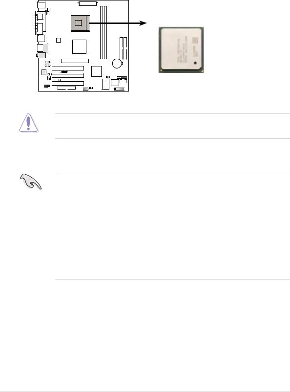
1.6Central Processing Unit (CPU)
1.6.1 Overview
The Intel® Pentium® 4 processor has a gold triangular mark on one corner. This mark indicates the processor Pin 1 that should match a specific corner of the CPU socket.
 Gold Arrow
P4SP-MX
P4SP-MX Socket 478
Incorrect installation of the CPU into the socket may bend the pins and severely damage the CPU!
Notes on Intel® Hyper-Threading Technology
• Hyper-Threading Technology is supported under Windows XP and Linux 2.4.x (kernel) and later versions only. Under Linux, use the Hyper-Threading compliler to compile the code. If you are using any other operating systems, disable the Hyper-Threading Techonology item in BIOS to ensure system stability and performance.
•It is recommended that you install WinXP Service Pack 1.
•Make sure to enable the Hyper-Threading Technology item in BIOS before installing a supported operating system.
•For more information on Hyper-Threading Technology, visit www.intel.com/ info/hyperthreading.
1-8 |
Chapter 1: Product introduction |
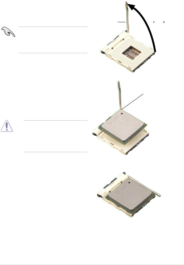
1.6.2 Installing the CPU
Follow these steps to install a CPU.
1.Locate the 478-pin ZIF socket on the motherboard.
2.Unlock the socket by pressing the lever sideways, then lift it up to a 90°- 100° angle.
Socket
Make sure that the socket lever is lifted up to 90°-100° angle, otherwise the CPU does not fit in completely.
3.Position the CPU above the socket such that its marked corner matches the base of the socket lever.
4.Carefully insert the CPU into the socket until it fits in place.
90 - 100
Gold Mark
The CPU fits only in one correct orientation. DO NOT force the CPU into the socket to prevent bending the pins and damaging the CPU!
5.When the CPU is in place, push down the socket lever to secure the CPU. The lever clicks on the side tab to indicate that it is locked.
6.Install a CPU heatsink and fan following the instructions that came with the heatsink package.
7.Connect the CPU fan cable to the CPU_FAN1 connector on the motherboard.
ASUS P4SP-MX motherboard user guide |
1-9 |
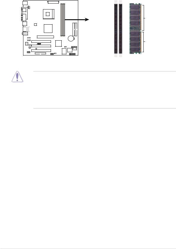
1.7System memory
1.7.1 DIMM sockets location
The following figure illustrates the location of the DDR DIMM sockets.
P4SP-MX |
104 Pins
80 Pins
P4SP-MX 184-Pin DDR DIMM Sockets
• Make sure to unplug the power supply before adding or removing DIMMs or other system components. Failure to do so may cause severe damage to both the motherboard and the components.
•When installing long AGP cards, it is recommended to install the memory modules first. Long AGP cards, when installed, may interfere with the memory sockets.
1.7.2Memory configurations
You may install 64MB, 128MB, 256MB, 512MB, and 1GB DDR DIMMs into the DIMM sockets.
1-10 |
Chapter 1: Product introduction |
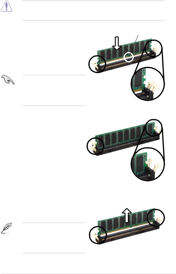
1.7.3 Installing a DIMM
Make sure to unplug the power supply before adding or removing DIMMs or other system components. Failure to do so may cause severe damage to both the motherboard and the components.
Follow these steps to install a DIMM.
1.Unlock a DIMM socket by pressing the retaining clips outward.
2.Align a DIMM on the socket such that the notch on the DIMM matches the break on the socket.
A DDR DIMM is keyed with a notch so that it fits in only one direction. DO NOT force a DIMM into a socket to avoid damaging the DIMM.
DDR DIMM notch
Unlocked retaining clip
3.Firmly insert the DIMM into the socket until the retaining clips snap back in place and the DIMM is properly seated.
Locked Retaining Clip
1.7.4 Removing a DIMM
Follow these steps to remove a DIMM.
1.Simultaneously press the retaining clips outward to unlock the DIMM.
Support the DIMM lightly with your fingers when pressing the retaining clips. The DIMM might get damaged when it flips out with extra force.
2. Remove the DIMM from the socket.
ASUS P4SP-MX motherboard user guide |
1-11 |

1.8Expansion slots
In the future, you may need to install expansion cards. The following sub-sections describe the slots and the expansion cards that they support.
Make sure to unplug the power cord before adding or removing expansion cards. Failure to do so may cause you physical injury and damage motherboard components.
1.8.1 Installing an expansion card
Follow these steps to install an expansion card.
1.Before installing the expansion card, read the documentation that came with it and make the necessary hardware settings for the card.
2.Remove the system unit cover (if your motherboard is already installed in a chassis).
3.Remove the bracket opposite the slot that you intend to use. Keep the screw for later use.
4.Align the card connector with the slot and press firmly until the card is completely seated on the slot.
5.Secure the card to the chassis with the screw you removed earlier.
6.Replace the system cover.
1.8.2 Configuring an expansion card
After installing the expansion card, configure the it by adjusting the software settings.
1.Turn on the system and change the necessary BIOS settings, if any. See Chapter 2 for information on BIOS setup.
2.Assign an IRQ to the card. Refer to the tables on the next page.
3.Install the software drivers for the expansion card.
1-12 |
Chapter 1: Product introduction |
 Loading...