


P4S800D-E
Deluxe
User Guide
Motherboard

E1381
First Edition
December 2003
Copyright © 2003 ASUSTeK COMPUTER INC. All Rights Reserved.
No part of this manual, including the products and software described in it, may be reproduced, transmitted, transcribed, stored in a retrieval system, or translated into any language in any form or by any means, except documentation kept by the purchaser for backup purposes, without the express written permission of ASUSTeK COMPUTER INC. (“ASUS”).
Product warranty or service will not be extended if: (1) the product is repaired, modified or altered, unless such repair, modification of alteration is authorized in writing by ASUS; or (2) the serial number of the product is defaced or missing.
ASUS PROVIDES THIS MANUAL “AS IS” WITHOUT WARRANTY OF ANY KIND, EITHER EXPRESS OR IMPLIED, INCLUDING BUT NOT LIMITED TO THE IMPLIED WARRANTIES OR CONDITIONS OF MERCHANTABILITY OR FITNESS FOR A PARTICULAR PURPOSE. IN NO EVENT SHALL ASUS, ITS DIRECTORS, OFFICERS, EMPLOYEES OR AGENTS BE LIABLE FOR ANY INDIRECT, SPECIAL, INCIDENTAL, OR CONSEQUENTIAL DAMAGES (INCLUDING DAMAGES FOR LOSS OF PROFITS, LOSS OF BUSINESS, LOSS OF USE OR DATA, INTERRUPTION OF BUSINESS AND THE LIKE), EVEN IF ASUS HAS BEEN ADVISED OF THE POSSIBILITY OF SUCH DAMAGES ARISING FROM ANY DEFECT OR ERROR IN THIS MANUAL OR PRODUCT.
SPECIFICATIONS AND INFORMATION CONTAINED IN THIS MANUAL ARE FURNISHED FOR INFORMATIONAL USE ONLY, AND ARE SUBJECT TO CHANGE AT ANY TIME WITHOUT NOTICE, AND SHOULD NOT BE CONSTRUED AS A COMMITMENT BY ASUS. ASUS ASSUMES NO RESPONSIBILITY OR LIABILITY FOR ANY ERRORS OR INACCURACIES THAT MAY APPEAR IN THIS MANUAL, INCLUDING THE PRODUCTS AND SOFTWARE DESCRIBED IN IT.
Products and corporate names appearing in this manual may or may not be registered trademarks or copyrights of their respective companies, and are used only for identification or explanation and to the owners’ benefit, without intent to infringe.
ii

Contents
Notices ............................................................................................ |
v |
Safety information .......................................................................... |
vi |
About this guide ............................................................................. |
vii |
P4S800D-E Deluxe specifications summary .................................. |
ix |
Chapter 1: Product introduction
1.1 |
Welcome! ........................................................................... |
1-1 |
|
1.2 |
Package contents ............................................................... |
1-1 |
|
1.3 |
Special features .................................................................. |
1-2 |
|
|
1.3.1 |
Product Highlights .................................................. |
1-2 |
|
1.3.2 |
Unique ASUS features ........................................... |
1-4 |
Chapter 2: Hardware information
2.1 |
Before you proceed ............................................................ |
1-1 |
|
2.2 |
Motherboard overview ........................................................ |
1-2 |
|
|
2.2.1 |
Placement direction ............................................... |
1-2 |
|
2.2.2 |
Screw holes ........................................................... |
1-2 |
|
2.2.3 |
Motherboard layout ................................................ |
1-3 |
|
2.2.4 |
Layout Contents ..................................................... |
1-4 |
2.3 |
Central Processing Unit (CPU) ........................................... |
1-6 |
|
|
2.3.1 |
Overview ................................................................ |
1-6 |
|
2.3.2 |
Installing the CPU .................................................. |
1-7 |
|
2.3.3 Installing the heatsink and fan ............................... |
1-9 |
|
|
2.3.4 Connecting the CPU fan cable ............................. |
1-11 |
|
2.4 |
System memory ............................................................... |
1-12 |
|
|
2.4.1 |
Overview .............................................................. |
1-12 |
|
2.4.2 |
Memory configurations ........................................ |
1-12 |
|
2.4.3 |
Qualified Vendor List ............................................ |
1-13 |
|
2.4.4 |
Installing a DIMM ................................................. |
1-14 |
|
2.4.5 |
Removing a DIMM ............................................... |
1-14 |
2.5 |
Expansion slots ................................................................ |
1-15 |
|
|
2.5.1 Installing an expansion card ................................ |
1-15 |
|
|
2.5.2 Configuring an expansion card ............................ |
1-15 |
|
|
2.5.3 |
Interrupt assignments .......................................... |
1-16 |
|
2.5.4 |
PCI slots .............................................................. |
1-17 |
|
2.5.5 |
AGP slot ............................................................... |
1-17 |
|
2.5.6 |
Wi-Fi slot .............................................................. |
1-18 |
2.6 |
Jumpers ............................................................................ |
1-19 |
|
iii

Contents
2.7 Connectors ....................................................................... |
1-21 |
|
2.7.1 |
Rear panel connectors ......................................... |
1-21 |
2.7.2 |
Internal connectors .............................................. |
1-22 |
Chapter 3: Powering up
3.1 |
Starting up for the first time ................................................ |
3-1 |
|
3.2 |
Powering off the computer ................................................. |
3-2 |
|
|
3.2.1 Using the OS shut down function .......................... |
3-2 |
|
|
3.2.2 Using the dual function power switch .................... |
3-2 |
|
3.3 |
ASUS POST Reporter™ .................................................... |
3-3 |
|
|
3.3.1 |
Vocal POST messages .......................................... |
3-3 |
|
3.3.2 |
Winbond Voice Editor ............................................ |
3-5 |
Chapter 4: BIOS Setup
4.1 Managing and updating your BIOS .................................... |
4-1 |
||
|
4.1.1 Creating a bootable floppy disk ............................. |
4-1 |
|
|
4.1.2 Using AFUDOS to update the BIOS ...................... |
4-2 |
|
|
4.1.3 Using AFUDOS to copy BIOS from PC ................. |
4-3 |
|
|
4.1.4 Using ASUS EZ Flash to update the BIOS ............ |
4-4 |
|
|
4.1.5 Recovering the BIOS with CrashFree BIOS 2 ....... |
4-5 |
|
|
4.1.6 |
ASUS Update ........................................................ |
4-7 |
4.2 |
BIOS Setup program .......................................................... |
4-9 |
|
|
4.2.1 |
BIOS menu screen .............................................. |
4-10 |
|
4.2.2 |
Menu bar .............................................................. |
4-10 |
|
4.2.3 |
Navigation keys ................................................... |
4-10 |
|
4.2.4 |
Menu items ........................................................... |
4-11 |
|
4.2.5 |
Sub-menu items .................................................... |
4-11 |
|
4.2.6 |
Configuration fields ............................................... |
4-11 |
|
4.2.7 |
Pop-up window ..................................................... |
4-11 |
|
4.2.8 |
Scroll bar ............................................................... |
4-11 |
|
4.2.9 |
General help ......................................................... |
4-11 |
4.3 |
Main menu ........................................................................ |
4-12 |
|
|
4.3.1 |
System Time [xx:xx:xxxx] ..................................... |
4-12 |
|
4.3.2 System Date [Day xx/xx/xxxx] ............................. |
4-12 |
|
|
4.3.3 Legacy Diskette A [1.44M, 3.5 in.] ....................... |
4-12 |
|
|
4.3.4 |
Language [English] .............................................. |
4-12 |
|
4.3.5 Primary and Secondary IDE Master/Slave .......... |
4-12 |
|
|
4.3.6 |
OnChip SATA Controller ...................................... |
4-14 |
|
4.3.7 |
System Information .............................................. |
4-14 |
iv

4.4 |
Advanced menu ............................................................... |
4-15 |
|
|
4.4.1 |
JumperFree Configuration ................................... |
4-15 |
|
4.4.2 |
CPU Configuration ............................................... |
4-17 |
|
4.4.3 |
Chipset ................................................................. |
4-18 |
|
4.4.4 |
Onboard Devices Configuration ........................... |
4-20 |
|
4.4.5 |
PCI PnP ............................................................... |
4-22 |
|
4.4.6 |
USB Configuration ............................................... |
4-24 |
|
4.4.7 |
Speech Configuration .......................................... |
4-25 |
|
4.4.8 |
Instant Music Configuration ................................. |
4-26 |
4.5 |
Power menu ..................................................................... |
4-27 |
|
|
4.5.1 |
Suspend Mode [Auto] .......................................... |
4-27 |
|
4.5.2 Repost Video on S3 Resume [No] ....................... |
4-27 |
|
|
4.5.3 ACPI 2.0 Support [No] ......................................... |
4-27 |
|
|
4.5.4 |
ACPI APIC Support [Enabled] ............................. |
4-27 |
|
2.5.5 |
APM Configuration ............................................... |
4-28 |
|
4.5.6 |
Hardware Monitor ................................................ |
4-29 |
4.6 |
Boot menu ........................................................................ |
4-31 |
|
|
4.6.1 |
Boot Device Priority ............................................. |
4-31 |
|
4.6.2 |
Removable Drives ............................................... |
4-32 |
|
4.6.3 |
Boot Settings Configuration ................................. |
4-32 |
|
4.6.4 |
Security ................................................................ |
4-34 |
4.7 |
Exit menu ......................................................................... |
4-37 |
|
Chapter 5: Software support
5.1 |
Install an operating system ................................................. |
5-1 |
|
5.2 |
Support CD information ...................................................... |
5-1 |
|
|
5.2.1 Running the support CD ........................................ |
5-1 |
|
|
5.2.2 |
Drivers menu ......................................................... |
5-2 |
|
5.2.3 |
Utilities menu ......................................................... |
5-3 |
|
5.2.4 |
ASUS Contact Information ..................................... |
5-4 |
|
5.2.5 |
Other information ................................................... |
5-5 |
5.3 |
Software Information ............................................................ |
5-7 |
|
|
5.3.1 |
ASUS MyLogo2™ .................................................. |
5-7 |
|
5.3.2 |
ASUS Instant Music ............................................... |
5-9 |
5.4 |
6-channel audio feature .................................................... |
5-12 |
|
|
5.4.1 |
Listening Environment options ............................. |
5-13 |
|
5.4.2 |
MIDI Music Synthesizer ....................................... |
5-14 |
5.5 |
SiS® |
RAID configurations ................................................. |
5-15 |
|
5.5.1 Install the Serial ATA (SATA) hard disks ............... |
5-16 |
|
v

|
5.5.2 |
BIOS utility operation (for RAID only) .................. |
5-17 |
|
5.5.3 |
SIS 180 RAID utility operation ............................. |
5-20 |
5.6 |
Creating a floppy with RAID driver ................................... |
5-23 |
|
5.7 |
AI Net feature ................................................................... |
5-24 |
|
Quick Reference Card
vi

Notices
Federal Communications Commission Statement
This device complies with Part 15 of the FCC Rules. Operation is subject to the following two conditions:
•This device may not cause harmful interference, and
•This device must accept any interference received including interference that may cause undesired operation.
This equipment has been tested and found to comply with the limits for a Class B digital device, pursuant to Part 15 of the FCC Rules. These limits are designed to provide reasonable protection against harmful interference in a residential installation. This equipment generates, uses and can radiate radio frequency energy and, if not installed and used in accordance with manufacturer’s instructions, may cause harmful interference to radio communications. However, there is no guarantee that interference will not occur in a particular installation. If this equipment does cause harmful interference to radio or television reception, which can be determined by turning the equipment off and on, the user is encouraged to try to correct the interference by one or more of the following measures:
•Reorient or relocate the receiving antenna.
•Increase the separation between the equipment and receiver.
•Connect the equipment to an outlet on a circuit different from that to which the receiver is connected.
•Consult the dealer or an experienced radio/TV technician for help.
The use of shielded cables for connection of the monitor to the graphics card is required to assure compliance with FCC regulations. Changes or modifications to this unit not expressly approved by the party responsible for compliance could void the user’s authority to operate this equipment.
Canadian Department of Communications Statement
This digital apparatus does not exceed the Class B limits for radio noise emissions from digital apparatus set out in the Radio Interference Regulations of the Canadian Department of Communications.
This class B digital apparatus complies with Canadian ICES-003.
vii

Safety information
Electrical safety
•To prevent electrical shock hazard, disconnect the power cable from the electrical outlet before relocating the system.
•When adding or removing devices to or from the system, ensure that the power cables for the devices are unplugged before the signal cables are connected. If possible, disconnect all power cables from the existing system before you add a device.
•Before connecting or removing signal cables from the motherboard, ensure that all power cables are unplugged.
•Seek professional assistance before using an adpater or extension cord. These devices could interrupt the grounding circuit.
•Make sure that your power supply is set to the correct voltage in your area. If you are not sure about the voltage of the electrical outlet you are using, contact your local power company.
•If the power supply is broken, do not try to fix it by yourself. Contact a qualified service technician or your retailer.
Operation safety
•Before installing the motherboard and adding devices on it, carefully read all the manuals that came with the package.
•Before using the product, make sure all cables are correctly connected and the power cables are not damaged. If you detect any damage, contact your dealer immediately.
•To avoid short circuits, keep paper clips, screws, and staples away from connectors, slots, sockets and circuitry.
•Avoid dust, humidity, and temperature extremes. Do not place the product in any area where it may become wet.
•Place the product on a stable surface.
•If you encounter technical problems with the product, contact a qualified service technician or your retailer.
viii

About this guide
This user guide contains the information you need when installing the motherboard.
How this guide is organized
This manual contains the following parts:
•Chapter 1: Product introduction
This chapter describes the motherboard features of the and the new technologies it supports.
•Chapter 2: Hardware information
This chapter lists the hardware setup procedures that you have to perform when installing system components. It includes description of the jumpers and connectors on the motherboard.
•Chapter 3: Powering up
This chapter describes the power up sequence, the vocal POST messages, and ways of shutting down the system.
•Chapter 4: BIOS setup
This chapter tells how to change system settings through the BIOS Setup menus. Detailed descriptions of the BIOS parameters are also provided.
•Chapter 5: Software support
This chapter describes the contents of the support CD that comes with the motherboard package.
ix
Conventions used in this guide
To make sure that you perform certain tasks properly, take note of the following symbols used throughout this manual.
DANGER/WARNING: Information to prevent injury to yourself when trying to complete a task.
CAUTION: Information to prevent damage to the components when trying to complete a task.
IMPORTANT: Information that you MUST follow to complete a task.
NOTE: Tips and additional information to aid in completing a task.
Typography
Bold Text
<Key> enclosed in the less-than and greater-than sign
<Multiple key names>
Indicates a menu or an item to select.
Indicates that you must press the enclosed key. Example: <Enter> indicates that you must press the Enter or Return key.
If you must press two or more keys simultaneously, the key names are linked with a plus sign (+). Example: <Ctrl+Alt+Del>
Words in Italics |
Italics are used to emphasize a point. |
Where to find more information
Refer to the following sources for additional information and for product and software updates.
1.ASUS websites
The ASUS websites worldwide provide updated information on ASUS hardware and software products. Refer to the ASUS contact information.
2.Optional documentation
Your product package may include optional documentation, such as warranty flyers, that may have been added by your dealer. These documents are not part of the standard package.
x
P4S800D-E Deluxe specifications summary
CPU
Chipset
Front Side Bus (FSB)
Memory
Expansion slots
Storage
IEEE 1394
Audio
LAN
Special features
Rear panel I/O
Socket 478 for Intel® Pentium® 4 / Celeron processors with speeds up to 3.06 GHz+
Supports Intel® Hyper-threading Technology
New power design supports next generation Intel Prescott CPU
SiS 655TX
SiS 964
800/533/400 MHz
4 x 184-pin DDR DIMM sockets for up to 4GB unbuffered non-ECC DDR400/333/266/200 SDRAM memory
Dual-channel memory architecture
1 x AGP 8X
5 x PCI
1 x ASUS Proprietary WiFi slot
SIS 964 SouthBridge supports
-2 x Serial ATA with RAID 0, RAID 1 function SIS 180 Serial/Ultra ATA RAID controller supports
-2 x Serial ATA + 2 x Ultra ATA with RAID 0, RAID 1, RAID 0+1 and JBOD
VIA VT6307 IEEE 1394 controller
Supports 2 x IEEE 1394 connectors
ADI AD1888 SoundMAX 6-channel audio CODEC S/PDIF interface
Marvell® Gigabit Ethernet controller
ASUS EZ Flash
ASUS CrashFree BIOS 2
ASUS Instant Music
ASUS POST Reporter
ASUS MyLogo2
ASUS Multi-Language BIOS
ASUS Q-Fan
AI Overclocking
1 x Parallel port
1 x Serial port
1 x PS/2 keyboard port
1 x PS/2 mouse port
4 x USB 2.0/USB 1.1 ports
1 x RJ-45 port
1 x SPDIF-out port
1 x IEEE 1394 port
Line In/Line Out/Microphone ports
(continued on the next page)
xi

P4S800D-E Deluxe specifications summary
Overclock Features |
ASUS JumperFree |
|
ASUS C.P.R. (CPU Parameter Recall) |
|
CPU, Memory, and AGP Voltage adjustable |
|
SFS (Stepless Frequency Selection) from 100MHz up to |
|
300MHz at 1MHz increment |
|
Adjustable FSB/DDR ratio, fixed AGP/PCI frequencies |
Internal I/O |
|
2 x USB 2.0 supports additiona 4 USB 2.0 ports |
|
|
4 x Serial ATA connectors |
|
2 x IDE connectors |
|
CPU/Chassis/Power fan connectors |
|
20-pin/4-pin ATX 12V power connectors |
|
Chassis intrusion |
|
IEEE 1394 connector |
|
GAME/MIDI connector |
|
CD/AUX audio connectors |
|
Front panel audio connector |
|
S/PDIF audio connector |
|
Serial port 2 connector |
|
Ultra ATA connector that support 2 drives |
BIOS features |
|
4Mb Flash ROM, ASUS JumperFree, AMI BIOS, PnP, |
|
|
DMI2.0, WfM2.0, SM BIOS 2.3, ASUS EZ Flash, ASUS |
|
Instant Music, ASUS MyLogo2, ASUS CrashFree BIOS 2, |
|
ASUS C.P.R., ASUS Multi-Language BIOS, ASUS Q-Fan, |
|
ASUS AI Overclocking |
Industry standard |
|
PCI 2.2, USB 2.0 |
|
Manageability |
|
WfM2.0, DMI 2.0, WOL, WOR, chassis intrusion |
|
Support CD contents |
|
Device drivers |
|
|
ASUS PC Probe |
|
ASUS Live Update |
|
Trend Micro™ PC-cillin 2002 anti-virus software |
Form Factor |
|
ATX form factor: 12 in x 9.6 in |
|
|
|
* Specifications are subject to change without notice.
xii

Chapter 1
This chapter describes the motherboard features and the new technologies it supports.
Product introduction

Chapter summary
1.1 |
Welcome! ........................................................ |
1-1 |
1.2 |
Package contents .......................................... |
1-1 |
1.3 |
Special features ............................................. |
1-2 |
ASUS P4S800D-E Deluxe motherboard

1.1Welcome!
Thank you for buying the ASUS® P4S800D-E Deluxe motherboard!
The motherboard delivers a host of new features and latest technologies making it another standout in the long line of ASUS quality motherboards!
The motherboard incorporates the Intel® Pentium® 4 processor in a 478-pin package coupled with the SIS® 655TX chipset to set a new benchmark for an effective desktop platform solution.
Supporting up to 4GB of system memory with DDR400/333/266/200 SDRAM, high-resolution graphics via an AGP 8X slot, Serial ATA support, RAID, IEEE 1394, USB 2.0, and 6-channel audio features, the motherboard takes you ahead in the world of power computing!
Before you start installing the motherboard, and hardware devices on it, check the items in your package with the list below.
1.2Package contents
Check your motherboard package for the following items.
ASUS P4S800D-E Deluxe motherboard
ASUS motherboard support CD
2 x SATA cable
1 x SATA power cable
1 x 2-port USB+GAME module w/ cable
1 x 1394 module
1 x 80-conductor ribbon cable for UltraDMA IDE drives
1 x 40-conductor IDE cable
1 x Ribbon cable for a 3.5-inch floppy drive
I/O shield
Bag of extra jumper caps
User Guide (includes Quick Reference Card)
Quick Setup Guide (Retail boxes only)
Jumper/Connector Sticker (Retail boxes only)
If any of the above items is damaged or missing, contact your retailer.
ASUS P4S800D-E Deluxe motherboard |
1-1 |

1.3Special features
1.3.1 Product Highlights
Latest processor technology
The motherboard comes with a 478-pin surface mount, Zero Insertion Force (ZIF) socket for the Intel® Pentium® 4 processor in the 478-pin package with 512/256KB L2 cache on 0.13 micron process. This motherboard supports 800/533/400 MHz system front side bus that allows 6.4GB/s, 4.3GB/s and 3.2GB/s data transfer rates, respectively. The motherboard also supports the Intel® Hyper-Threading Technology and the next-generation Intel® Prescott CPU.
Dual Channel DDR memory support
Employing the Double Data Rate (DDR) memory technology, the motherboard supports up to 4GB of system memory using DDR400/333/ 266/200 DIMMs. The ultra-fast 400MHz memory bus delivers the required bandwidth for the latest 3D graphics, multimedia, and Internet applications.
SiS® Advanced HyperStreaming Architecture
The SiS® 655TX integrates the latest SIS® Advanced HyperStreaming™ technology that provides a two-level smart arbitration mechanism to schedule commands and data in the interface to improve the bus utilization and efficiency of the CPU and other devices. Also, with the Advanced HyperStreaming™ technology flow control mechanism and intelligent arbitration algorithm, the bandwidth between interfaces with other systems is increased and improves the transfer rate from the CPU to the chipsets giving an enhanced system performance.
Serial ATA solution with
RAID 0, RAID 1, RAID 0+1, and JBOD support
The motherboard supports two interfaces compliant to the Serial ATA (SATA) specification, an evolutionary replacement of the Parallel ATA storage interface. The Serial ATA specification allows for thinner, more flexible cables with lower pin count, reduced voltage requirement, up to 150 MB/s data transfer rate, and software compatibility with legacy Parallel ATA. With the integrated controller in the SIS 964 chipset and the SiS 180, the motherboard supports RAID0, RAID1, RAID 0+1 and JBOD configuration using UltraATA133 drives and SATA drives.
1-2 |
Chapter 1: Product introduction |

AGP 8X support
AGP 8X (AGP 3.0) is the next generation VGA interface specification that enables enhanced graphics performance with high bandwidth speeds up to 2.12 GB/s. See page 2-17.
S/PDIF out
The motherboard supports S/PDIF out function turns your computer into a high-end entertainment system with digital connectivity to powerful speaker systems.
IEEE 1394 support
The IEEE 1394 interface provides high-speed and flexible PC connectivity to a wide range of peripherals and devices compliant to IEEE 1394a standards. The IEEE 1394 interface allows up to 400Mbps transfer rates through simple, low-cost, high-bandwidth asynchronous (real-time) data interfacing between computers, peripherals, and consumer electronic devices such as camcorders, VCRs, printers,TVs, and digital cameras.
8 USB 2.0 ports
The motherboard implements the new Universal Serial Bus (USB) 2.0 specification, extending the connection speed from 12 Mbps on USB 1.1 to a fast 480 Mbps on USB 2.0 - supporting up to 8 USB 2.0 ports. The higher bandwidth of USB 2.0 allows connection of devices such as high resolution video conferencing cameras, next generation scanners and printers, and fast storage units. USB 2.0 is backward compatible with USB 1.1.
6-channel digital audio
The ADI AD1888 SoundMAX AC ’97 audio CODEC is onboard to provide 6-channel audio playback for 5.1 surround sound, over 90dB dynamic range, and stereo MIC PREAMP.
ASUS P4S800D-E Deluxe motherboard |
1-3 |

1.3.2 Unique ASUS features
ASUS Wi-Fi slot
The ASUS Wi-Fi slot is designed for the ASUS WiFi-b™ add-on card to set up an environment for wireless LAN. The ASUS WiFi-b™ add-on card bundles the exclusive Software AP (Access Point) to save the extra cost of a stand-alone AP. In addition, the card comes with user-friendly utilities and applications that allow quick connection to notebooks, PDAs and other wireless LAN peripherals. See page 2-18.
AI NET solution
The Marvell® Gigabit PCI LAN controller chipset is onboard to provide a single-chip solution for LAN on Motherboard (LOM) applications. The controller integrates 32-bit 10/100/1000BASE-T Gigabit Ethernet Media Access Control (IEEE 802.3 compliant) and Physical Layer Transceiver solution to support high performance network applications. The controller is equipped with the net-diagnosing utility, VCT (Virtual Cable Tester), that intelligently diagnoses and reports cable faults from a remote location up to 100 meters. This feature helps maintain a more stable network connection. Se page 5-24.
AI BIOS solution
The AI BIOS is a combination of three ASUS intelligent solutions: Q-Fan, POST Reporter, and CrashFree BIOS2.
ASUS Q-Fan technology
The ASUS Q-Fan technology smartly adjusts the fan speeds according to the system loading to ensure quiet, cool, and efficient operation. See page 4-30.
ASUS POST Reporter
The motherboard offers a new exciting feature called the ASUS POST Reporter to provide friendly voice messages and alerts during the PowerOn Self-Tests (POST). Through an added external speaker, you will hear the messages informing you of the system boot status and causes of boot errors, if any. The bundled Winbond Voice Editor software allows you to customize the voice messages, and provides multi-language support. See page 3-3.
1-4 |
Chapter 1: Product introduction |

CrashFree BIOS 2
This feature allows you to restore the original BIOS data from the ASUS support CD in case when the BIOS codes and data are corrupted. This protection eliminates the need to buy a replacement ROM chip. See page 4-5.
ASUS MyLogo2™
This new feature present in the motherboard allows you to personalize and add style to your system with customizable boot logos. See page 5-7.
C.P.R. (CPU Parameter Recall)
The C.P.R. feature of the motherboard BIOS allows automatic re-setting to the BIOS default settings in case the system hangs due to overclocking. When the system hangs due to overclocking, C.P.R. eliminates the need to open the system chassis and clear the RTC data. Simply shut down and reboot the system, and BIOS automatically restores the CPU default setting for each parameter. See page 4-4.
ASUS EZ Flash BIOS
With the ASUS EZ Flash, you can easily update the system BIOS even before loading the operating system. No need to use a DOS-based utility or boot from a floppy disk.
ASUS Multi-language BIOS
The multi-language BIOS allows you to select the language of your choice from the available options. The localized BIOS menus allow you to configure easier and faster. Visit the ASUS website for information on the supported languages. See page 4-12.
Instant Music
This unique feature allows you to playback audio files even without booting the system to Windows™. Just press the ASUS Instant Music special function keys and enjoy the music! See pages 4-26, 5-9.
ASUS P4S800D-E Deluxe motherboard |
1-5 |

1-6 |
Chapter 1: Product introduction |
Chapter 2
This chapter lists the hardware setup procedures that you have to perform when installing system components. It includes description of the jumpers and connectors on the motherboard.
Hardware information

Chapter summary
2.1 |
Before you proceed ....................................... |
2-1 |
2.2 |
Motherboard overview ................................... |
2-2 |
2.3 |
Central Processing Unit (CPU) ..................... |
2-6 |
2.4 |
System memory ........................................... |
2-12 |
2.5 |
Expansion slots ........................................... |
2-15 |
2.6 |
Jumpers ........................................................ |
2-19 |
2.7 |
Connectors ................................................... |
2-21 |
ASUS P4S800D-E Deluxe motherboard
2.1Before you proceed
Take note of the following precautions before you install motherboard components or change any motherboard settings.
1.Unplug the power cord from the wall socket before touching any component.
2.Use a grounded wrist strap or touch a safely grounded object or to a metal object, such as the power supply case, before handling components to avoid damaging them due to static electricity.
3.Hold components by the edges to avoid touching the ICs on them.
4.Whenever you uninstall any component, place it on a grounded antistatic pad or in the bag that came with the component.
5.Before you install or remove any component, ensure that the ATX power supply is switched off or the power cord is detached from the power supply. Failure to do so may cause severe damage to the motherboard, peripherals, and/or components.
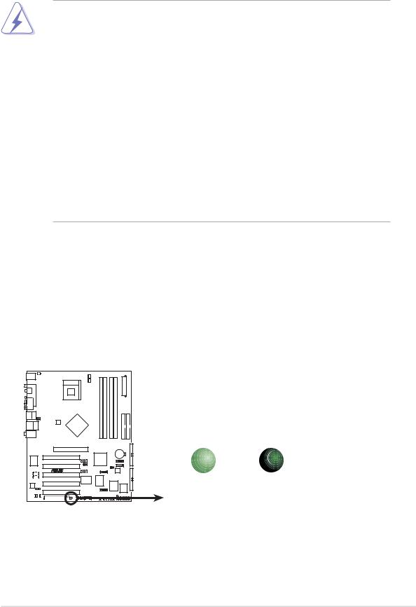
Onboard LED
The motherboard comes with a standby power LED. When lit, the green LED indicates that the system is ON, in sleep mode, or in soft-off mode, a reminder that you should shut down the system and unplug the power cable before removing or plugging in any motherboard component. The illustration below shows the location of the onboard LED.
|
SB_PWR1 |
|
P4S800D-E |
ON |
OFF |
|
Standby |
Powered |
|
Power |
Off |
P4S800D-E Onboard LED |
|
|
ASUS P4S800D-E Deluxe motherboard |
2-1 |

2.2Motherboard overview
Before you install the motherboard, study the configuration of your chassis to ensure that the motherboard fits into it.
Make sure to unplug the power cord before installing or removing the motherboard. Failure to do so may cause you physical injury and damage motherboard components.
2.2.1 Placement direction
When installing the motherboard, make sure that you place it into the chassis in the correct orientation. The edge with external ports goes to the rear part of the chassis as indicated in the image below.
2.2.2 Screw holes
Place nine (9) screws into the holes indicated by circles to secure the motherboard to the chassis.
Do not overtighten the screws! Doing so may damage the motherboard.
Place this side towards the rear of the chassis
2-2 |
Chapter 2: Hardware information |
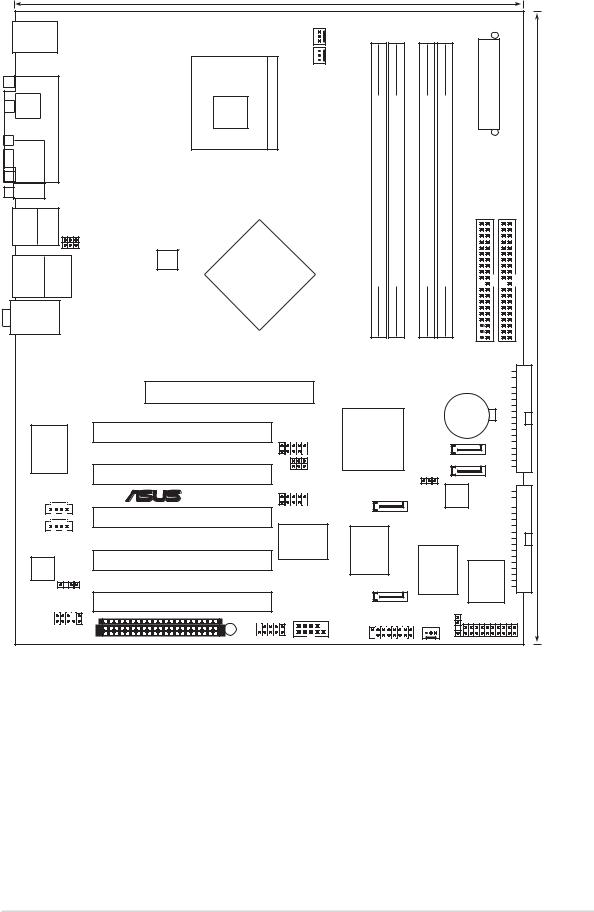
2.2.3 |
Motherboard layout |
|
|
|
|
|
|
|
|||||
|
|
|
|
|
24.5cm (9.6in) |
|
|
|
|
|
|
|
|
PS/2KBMS |
|
|
|
|
|
|
|
|
|
|
|||
T: Mouse |
|
|
PWR_FAN1 |
|
|
|
|
|
|
||||
B: Keyboard |
|
|
|
|
|
Connector |
|
|
|||||
|
|
|
|
|
|
|
|
|
|||||
|
|
|
|
Socket 478 |
CPU_FAN1 |
|
|
|
|
|
|||
|
|
|
PORTPARALLEL |
|
module) |
module) |
module) |
module) |
ATXPower |
|
|
||
SPDIF_O |
|
|
|
|
|
|
|||||||
|
|
|
|
|
(64A1DIMMbit,184-pin |
(64A2DIMMbit,184-pin |
(64B1DIMMbit,184-pin |
(64B2DIMMbit,184-pin |
|
|
|
||
COM1 |
|
|
|
|
IDE1SEC |
IDE1PRI |
|
||||||
|
|
|
|
|
|
|
|
|
|
|
|||
Bottom: |
Top: |
|
|
|
|
|
|
|
|
|
|
||
USB1 |
|
|
|
|
|
|
|
|
|
|
|
||
USB2 |
|
1394 |
USBPW12 |
|
|
|
|
|
|
|
|
|
|
|
|
|
|
|
|
|
|
|
|
|
|
|
|
|
|
|
|
USBPW34 |
SiS |
|
|
|
|
|
|
|
|
T: USB3 |
RJ-45 |
ATX12V1 |
|
DDR |
DDR |
DDR |
DDR |
|
|
|
|||
655 |
|
|
|
|
|||||||||
USB2.0 |
Top: |
|
|
|
|
|
|
|
|
|
|
||
B: USB4 |
|
|
TX |
|
|
|
|
|
|
|
(12.0in) |
||
|
|
|
|
|
|
|
|
|
|
|
|
||
Top:Line In |
|
|
|
|
|
|
|
|
|
|
|||
|
|
|
|
|
|
|
|
|
|
|
|||
Center:Line Out |
|
|
|
|
|
|
|
|
|
|
|||
Below:Mic In |
|
|
|
|
|
|
|
|
|
30.5cm |
|||
|
|
|
|
Accelerated Graphics Port (AGP1) |
|
|
|
|
|
FLOPPY1 |
|||
|
|
|
|
|
|
|
|
|
|
|
|||
|
|
|
|
|
|
|
|
|
|
|
CR2032 3V |
|
|
|
|
|
|
|
|
|
|
|
|
|
Lithium Cell |
|
|
|
|
|
|
PCI1 |
|
|
SiS |
|
|
CMOS Power |
|
|
|
|
Marrell 88E8001 LANPCI |
|
|
|
|
|
|
|
|
||||
|
|
|
USB56 |
964 |
|
SATA2 |
|
|
|
||||
|
|
|
|
|
|
|
|
|
|
||||
|
|
|
|
PCI2 |
|
USBPW56 |
|
|
SATA1 |
|
|
|
|
|
|
|
|
|
|
CLRTC1 |
|
|
|
|
|||
|
|
|
|
|
|
USBPW78 |
|
|
|
RAID1 |
|
||
|
|
|
|
® |
|
|
|
|
|
|
|
|
|
|
|
|
|
|
|
USB78 |
SATA4 |
|
|
|
|
|
|
CD1 |
|
PCI3 |
|
|
|
|
|
|
PRI_ |
|
|||
|
|
|
|
|
|
|
|
|
|||||
AUX1 |
|
|
|
|
|
|
|
|
|
||||
|
P4S800D-E |
VIA |
|
|
|
|
|
|
|
||||
|
|
|
|
180 |
|
|
|
|
|
|
|||
|
|
|
|
|
|
VT6307 |
|
|
|
|
|
|
|
|
|
SPDIF_OUT |
|
SATA3SiS |
|
Super I/O |
4Mbit Firmware Hub |
|
|
||||
|
Audio |
PCI4 |
|
|
|
|
|
|
|
|
|
||
Codec |
|
|
|
|
|
|
|
|
|
|
|||
|
|
|
|
PCI5 |
|
|
|
|
|
CHASSIS1 |
|
|
|
|
|
|
|
|
SB_PWR1 |
COM2 |
|
|
CHA_FAN1 |
|
|
||
|
|
|
FP_AUDIO |
|
|
|
|
|
|
||||
|
|
|
|
|
GAME1 |
|
|
|
|
|
|
||
|
|
|
|
WIFI |
IE1394_2 |
|
|
|
PANEL1 |
|
|||
|
|
|
|
|
|
|
|
|
|||||
ASUS P4S800D-E Deluxe motherboard |
2-3 |

2.2.4 |
Layout Contents |
|
|
|
|
Slots |
|
|
1. |
PCI slots |
p. 2-17 |
2. |
AGP slot |
p. 2-17 |
3. |
Wi-Fi slot |
p. 2-18 |
4. |
DDR DIMM slots |
p. 2-12 |
|
|
|
Jumpers |
|
|
1. |
Clear RTC RAM (3-pin CLRTC1) |
p. 2-19 |
2. |
USB device wake-up (3-pin USBPW12, USBPW34, |
|
|
USBPW56, USBPW78) |
p. 2-20 |
|
|
|
Rear Panel Connectors |
|
|
|
|
|
1. |
PS/2 mouse port |
p. 2-21 |
2. |
Parallel port |
p. 2-21 |
3. |
IEEE 1394 port |
p. 2-21 |
4. |
Gigabit LAN port (RJ-45) |
p. 2-21 |
5. |
Line In jack |
p. 2-21 |
6. |
Line Out jack |
p. 2-21 |
7. |
Microphone jack |
p. 2-21 |
8. |
USB 2.0 ports 3 and 4 |
p. 2-21 |
9. |
USB 2.0 ports 1 and 2 |
p. 2-22 |
10. |
Serial connector |
p. 2-22 |
11. |
S/PDIF out jack |
p. 2-22 |
12. |
PS/2 keyboard port |
p. 2-22 |
2-4 |
Chapter 2: Hardware information |

Internal Connectors
1. |
Primary IDE connector (40-1 pin PRI_IDE1) |
p. 2-22 |
2. |
Secondary IDE connector (40-1 pin SEC_IDE1) |
p. 2-22 |
3. |
Floppy disk connector (34-1 pin FLOPPY1) |
p. 2-23 |
4. |
RAID ATA connector (40-1 pin PRI_RAID1) |
p. 2-23 |
5. |
Serial ATA connectors (7-pin SATA1, SATA2, SATA3, SATA4 ) |
p. 2-24 |
6. |
CPU fan connector (3-pin CPU_FAN1) |
p. 2-25 |
7. |
Power fan connector (3-pin PWR_FAN1) |
p. 2-25 |
8. |
Chassis fan connector (3-pin CHA_FAN1) |
p. 2-25 |
9. |
Serial Port 2 connector (10-1 pin COM2) |
p. 2-25 |
10. |
ATX power connector (20-pin ATXPWR1) |
p. 2-26 |
11. |
ATX 12V power connector (4-pin ATX12V1) |
p. 2-26 |
12. |
USB headers (10-1 pin USB56, USB78) |
p. 2-27 |
13. |
CD connector (4-pin CD1) |
p. 2-28 |
14. |
AUX connector (4-pin AUX1) |
p. 2-28 |
15. |
IEEE 1394 connector (10-1 pin IE1394_2) |
p. 2-28 |
16. |
Front panel audio connector (10-1 pin FP_AUDIO1) |
p. 2-29 |
17. |
Digital audio connector (6-1 pin SPDIF_OUT1) |
p. 2-29 |
18. GAME/MIDI connector (16-1 pin GAME1) |
p. 2-30 |
|
19. |
System panel connector (20-pin PANEL1) |
p. 2-30 |
|
- System Power LED Lead (Green 3-1 pin PLED) |
|
|
- System Warning Speaker Lead (Orange 4-pin SPKR) |
|
|
- Reset Switch (Blue 2-pin RESET) |
|
|
- ATX Power Switch (Yellow 2-pin PWRBTN) |
|
|
- Hard Disk Activity LED (Red 2-pin IDE_LED) |
|
ASUS P4S800D-E Deluxe motherboard |
2-5 |
2.3Central Processing Unit (CPU)
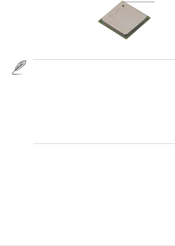
2.3.1 Overview
The motherboard comes with a surface mount 478-pin Zero Insertion Force (ZIF) socket designed for the Intel® Pentium® 4 processor. Take note of the marked corner (with
gold triangle) on the CPU. This mark should match a specific corner on the socket to ensure correct installation.
Notes on Intel® Hyper-Threading Technology
1. This motherboard supports Intel Pentium 4 CPUs with HyperThreading Technology.
2.Hyper-Threading Technology is supported under Windows XP and Linux 2.4.x (kernel) and later versions only. Under Linux, use the Hyper-Threading compliler to compile the code. If you are using any other operating systems, disable the Hyper-Threading Techonology item in BIOS to ensure system stability and performance.
3.It is recommended that you install WinXP Service Pack 1.
4.Make sure to enable the Hyper-Threading Technology item in BIOS before installing a supported operating system.
5.For more information on Hyper-Threading Technology, visit www.intel.com/info/hyperthreading.
To use the Hyper-Threading Technology on this motherboard:
1.Buy an Intel Pentium 4 CPU that supports Hyper-Threading Technology. Install the CPU.
2.Power up the system and enter BIOS Setup (see Chapter 4). Under the Boot Menu, make sure that the item Hyper-Threading Technology is set to Enabled. The item appears only if you installed a CPU that supports Hyper-Threading Technology.
3.Reboot the computer.
2-6 |
Chapter 2: Hardware information |
2.3.2 Installing the CPU
Follow these steps to install a CPU.
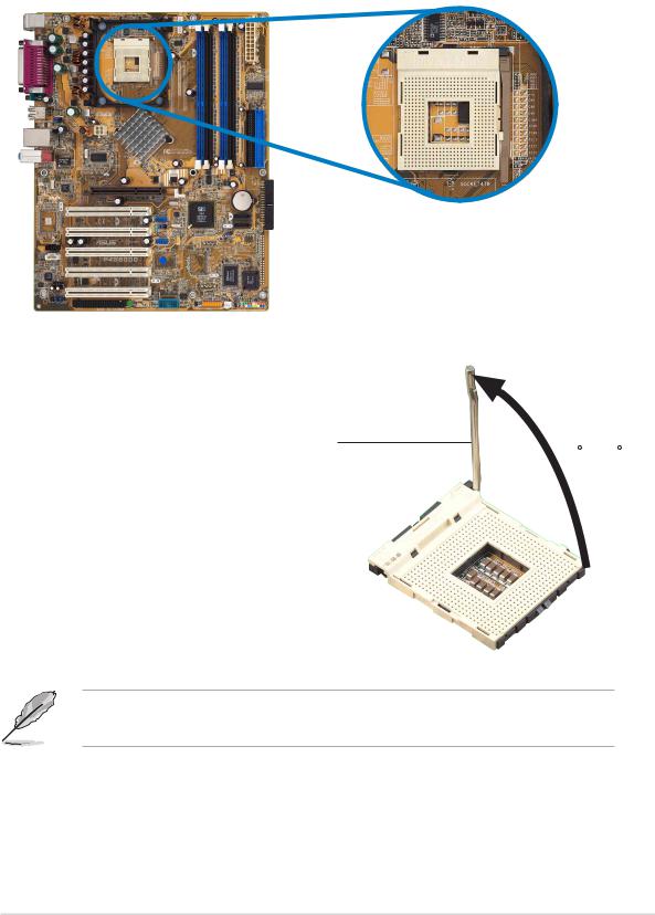
1. Locate the 478-pin ZIF socket on the motherboard.
2.Unlock the socket by pressing the lever sideways, then lift it up to a 90°-100° angle.
Socket Lever
90 - 100
Make sure that the socket lever is lifted up to 90°-100° angle, otherwise the CPU does not fit in completely.
ASUS P4S800D-E Deluxe motherboard |
2-7 |
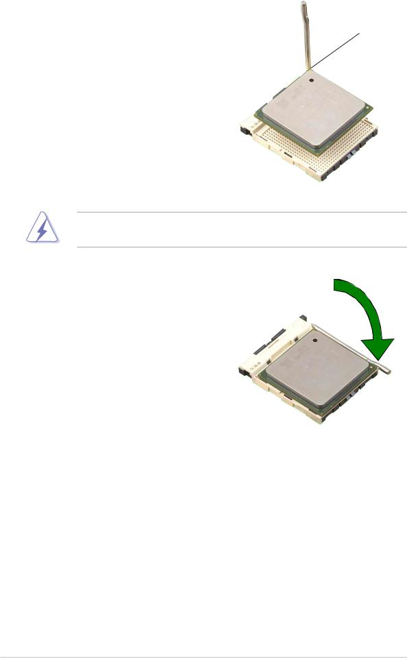
3. Position the CPU above the |
|
socket such that its marked |
Gold Mark |
corner matches the base of the |
|
socket lever. |
|
4.Carefully insert the CPU into the socket until it fits in place.
The CPU fits only in one correct orientation. DO NOT force the CPU into the socket to prevent bending the pins and damaging the CPU!
5.When the CPU is in place, push down the socket lever to secure the CPU. The lever clicks on the side tab to indicate that it is locked.
2-8 |
Chapter 2: Hardware information |
 Loading...