


POWER AMPLIFIER
XS350
XS250
Owner’s Manual
POWER |
|
350 |
|
|
POWER AMPLIFIER XS SERIES |
ON OFF |
|
|
POWER |
SIGNAL CLIP |
PROTECTION CLIP SIGNAL |
|
CH A |
CH B |
E

Introduction
Thank you for purchasing a Yamaha XS350, XS250 series power amplifier.
This series of audio amps was developed from Yamaha's wealth of experience in building PA equipment and its tradition of careful attention to every detail of circuit design. These amps feature high power and superb quality together with superior reliability and stability, guaranteeing the highest possible audio performance.
Main features of the XS350, XS250 series
•The unit is equipped with two types of inputs: balanced XLR and barrier strip, and two types of outputs: barrier strip and binding post. This combination of inputs and outputs affords flexible capabilities and accommodates a wide range of applications.
•Three operating modes are provided: STEREO mode in which CHANNEL A and B operate independently, PARALLEL mode in which a mono source is output by two amp systems, and BRIDGE mode in which the unit operates as a single high-power amplifier.
•A high pass/low pass switchable filter is provided for each channel. The high pass filter features a continuous controller that allows you to change cut-off frequencies between 25 Hz and 150 Hz.
•A SIGNAL indicator and CLIP indicator is provided for each channel.
•The PROTECTION indicator shows the status of protective circuitry such as power-on/off protection, output muting, and the DC detection circuit.
•Variable-speed low-noise fan(s) ensures high reliability even under demanding conditions.
This owner's manual covers the two models XS350, XS250. In order to take full advantage of your power amp and enjoy long and trouble-free operation, please read this owner's manual carefully before use.
WARNING: THIS APPARATUS MUST BE EARTHED
IMPORTANT
THE WIRES IN THIS MAINS LEAD ARE COLOURED IN
ACCORDANCE WITH THE FOLLOWING CODE:
GREEN-AND-YELLOW : EARTH
BLUE : NEUTRAL
BROWN : LIVE
As the colours of the wires in the mains lead of this apparatus may not correspond with the coloured markings identifying the terminals in your plug, proceed as follows:
The wire which is coloured GREEN and YELLOW must be connected to the terminal in the plug which is marked by the letter E or by the safety earth symbol  or coloured GREEN and YELLOW.
The wire which is coloured BLUE must be connected to the terminal which is marked with the letter N or coloured BLACK.
The wire which is coloured BROWN must be connected to the terminal which is marked with the letter L or coloured RED.
*This applies only to products distributed by YAMAHA KEMBLE MUSIC (U.K.) LTD.
2

Precautions
•Connect this unit’s power cord only to an AC outlet of the type stated in this Owner’s Manual or as marked on the unit. Failure to do so is a fire and electrical shock hazard.
•Do not allow water to enter this unit or allow the unit to become wet. Fire or electrical shock may result.
•Do not place heavy objects, including this unit, on top of the power cord. A damaged power cord is a fire and electrical shock hazard. In particular, be careful not to place heavy objects on a power cord covered by a carpet.
•Do not scratch, bend, twist, pull, or heat the power cord. A damaged power cord is a fire and electrical shock hazard.
•Do not remove the unit’s cover. You could receive an electrical shock. If you think internal inspection, maintenance, or repair is necessary, contact your dealer.
•Do not modify the unit. Doing so is a fire and electrical shock hazard.
•If the power cord is damaged (i.e., cut or a bare wire is exposed), ask your dealer for a replacement. Using the unit with a damaged power cord is a fire and electrical shock hazard.
•If you notice any abnormality, such as smoke, odor, or noise, or if a foreign object or liquid gets inside the unit, turn it off immediately. Remove the power cord from the AC outlet. Consult your dealer for repair. Using the unit in this condition is a fire and electrical shock hazard.
•Should this unit be dropped or the cabinet be damaged, turn the power switch off, remove the power plug from the AC outlet, and contact your dealer. If you continue using the unit without heeding this instruction, fire or electrical shock may result.
•Hold the power cord plug when disconnecting it from an AC outlet. Never pull the cord. A damaged power cord is a potential fire and electrical shock hazard.
•Do not touch the power plug with wet hands. Doing so is a potential electrical shock hazard.
•This unit has ventilation holes at the front, rear and sides to prevent the internal temperature rising too high. Do not block them. Blocked ventilation holes are a fire hazard.
•Allow enough free space around the unit for normal ventilation. This should be: 10 cm at the sides, 30 cm behind, and 20 cm above.
These distances should also be adopted when rackmounting the unit. For normal ventilation during use, remove the rear of the rack or open a ventilation hole. If the airflow is not adequate, the unit will heat up inside and may cause a fire.
•To mount several of these units in an EIA-compliant rack, refer to the rack mounting instructions on page 11.
•Use only speaker cables when connecting speakers to amplifier outputs. Using other types of cables is a fire hazard.
•Do not use this amplifier for any purpose other than driving loudspeakers.
•XLR-type connectors are wired as follows:
pin 1: ground, pin 2: hot (+), and pin 3: cold (–).
•Using a mobile telephone near this unit may induce noise. If noise occurs, use the telephone away from the unit.
•Clean the contacts of the phone plug before connecting it to the SPEAKERS jack of this unit. Dirty contacts may generate heat.
Contents |
|
Controls and Functions ............................................. |
4 |
Front Panel ........................................................... |
4 |
Rear Panel ........................................................... |
5 |
Speaker Impedance ............................................. |
7 |
Caution for Speaker Connection ............................... |
9 |
Rack Mounting ........................................................ |
10 |
Mounting in an EIA standard rack ..................... |
10 |
Portable Rack Mounting .................................... |
11 |
Fixed Installation Mounting ................................ |
11 |
General Specifications ....................................... |
12 |
Specifications .......................................................... |
12 |
Block Diagram .................................................... |
13 |
Dimensions ........................................................ |
13 |
Troubleshooting ...................................................... |
14 |
3
Controls and Functions
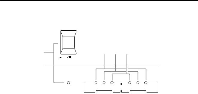
■ Front Panel
POWER
1 |
2 |
3 |
4 |
ON |
OFF |
|
|
POWER |
SIGNAL CLIP |
PROTECTION CLIP SIGNAL |
|
CH A |
CH B |
1POWER switch and indicator
This is the main POWER switch. Press to power ON the amplifier. Press again to power OFF. The POWER indicator lights up when the amplifier is powered ON.
2SIGNAL indicators
These green LED indicators light up when the
respective channel’s output signal exceeds 2 Vrms. This is equivalent to 1/2 W into 8Ω , 1 W into 4Ω .
3CLIP indicators
These red LED indicators light up when the respective channel’s output signal distortion exceeds 1% (i.e. clipping). Output signal clipping is usually due to excessive input signal levels.
4PROTECTION indicator
These LED indicators light up to indicate that the protection circuit is working. The speaker system is disconnected from the amplifier outputs and no sound is output from the speakers.
The protection circuit is activated in the following situations:
•When the amplifier is powered on:
The protection circuit is activated for approximately 3 seconds when the amplifier is powered on. After 3 seconds, the protection system is deactivated automatically, and the amplifier is ready to use.
•If a DC voltage is present at the amplifier’s outputs:
If the DC voltage problem is corrected, normal amplifier operation resumes.
•If overheating occurs:
Turn off the power to the amplifier to cool down the unit and consult the Precautions section of this manual to improve the vent condition, if necessary. Turn the power on to the amplifier after it cools down.
4

■ Rear Panel
1 |
|
2 |
|
3 |
|
|
|
|
4 |
|
|
|
||
FILTER |
|
|
|
|
|
|
|
|
|
|
|
|
|
|
CHANNEL B |
CHANNEL A |
|
|
|
|
|
|
|
|
|
|
|
|
|
FREQ. |
FREQ. |
|
|
|
|
|
|
|
|
|
|
|
|
|
90 |
90 |
20 |
15 |
20 |
15 |
|
|
|
|
|
|
|
|
|
|
|
|
|
|
|
|
|
|
|
|
||||
50 |
50 |
|
10 |
|
10 |
|
|
|
|
|
|
|
|
|
|
|
25 |
25 |
|
|
|
|
|
|
|
|
|
||
125 |
125 |
6 |
6 |
|
|
|
|
|
|
|
|
|
||
30 |
30 |
|
|
|
|
|
|
|
|
|
||||
|
|
3 |
3 |
|
|
|
|
|
|
|
|
|
||
|
|
40 |
40 |
|
|
|
|
|
|
|
|
|
||
|
|
|
|
|
|
|
|
|
|
|
|
|
||
25 Hz 150 |
25 Hz 150 |
00 –dB 0 |
00 –dB 0 |
|
|
|
|
|
|
|
|
|
||
|
|
CHANNEL B |
CHANNEL A |
|
|
|
|
|
SPEAKERS |
|
|
|
||
LOW CUT |
LOW CUT |
|
MODE |
|
|
|
|
|
|
|
|
|
||
|
|
|
|
|
|
|
B-1 |
CHANNEL |
A-1 |
|||||
SUB WOOFER |
SUB WOOFER |
|
|
|
|
|
|
|
||||||
|
BRIDGE |
|
|
|
|
|
|
4-8Ω /CHANNEL (STEREO) |
||||||
OFF |
OFF |
|
STEREO |
PARALLEL |
|
|
B-2 |
CHANNEL |
A-2 |
– |
+ |
+ |
– |
|
|
|
|
|
|
|
|
||||||||
|
|
|
|
|
|
|
4-8Ω /CHANNEL (STEREO) |
|
|
|
|
|||
|
|
|
|
|
|
|
– |
+ |
+ |
– |
|
|
|
|
INPUT |
|
|
|
INPUT |
|
|
|
|
|
|
|
|
||
CHANNEL B |
CHANNEL A |
|
|
CHANNEL B |
CHANNEL A |
(BRIDGE) |
|
|
|
|
(–) |
(+) |
|
|
|
|
|
|
|
G |
G |
(PARALLEL) |
|
|
|
|
|
||
|
|
|
|
|
(–) |
(+) |
|
|
|
|
|
|||
|
|
|
|
|
|
|
|
|
|
|
|
|
||
|
|
|
|
|
|
|
|
8-16Ω |
(BRIDGE) |
|
|
8-16Ω |
(BRIDGE) |
|
(BRIDGE)
(PARALLEL)
5
1Frequency controls/Filter select switches (CHANNEL A, B)
These knobs and sliding switches are used to select a filter type and control the cut-off frequencies respectively. You can select one of the following filter type:
LOW CUT
SUB WOOFER
OFF
|
|
|
|
........................OFF |
Turns the filter off. |
||
SUB WOOFER ...... |
Turns the low pass filter on. |
||
|
(The cut-off frequencies for |
||
|
the low pass filter are fixed.) |
||
|
This setting is suitable when |
||
|
using the unit as an amplifier |
||
|
for a subwoofer. |
||
LOW CUT .............. |
Turns the high pass (low cut) |
||
|
filter on. (The cut-off frequen- |
||
|
cies are variable.) |
||
If you select “LOW CUT,” you can use the frequency controls to adjust the cut-off frequencies in the range of 25 Hz to 150 Hz.
FREQ.
90
50
125
25 Hz 150
Note: In BRIDGE mode, only the frequency control and filter select switch for Channel A are available.
6
2Volume controls (CHANNEL A, B)
These knobs enable you to adjust the output level of Channels A and B in the range between –∞ dB and
0 dB. In BRIDGE mode, only the volume control for Channel A is available.
3STEREO/BRIDGE/PARALLEL switch
This slide switch is used to set the amplifier operating mode: STEREO, BRIDGE or PARALLEL.
BRIDGE
STEREO 

 PARALLEL
•STEREO mode
In this mode, channels A and B operate independently (as a conventional stereo amp).
The CHANNEL A input signal will be output from the CHANNEL A output jacks, and the CHANNEL B input signal will be output from the CHANNEL B output jacks.
•BRIDGE mode
In this mode, the CHANNEL A input signal will be output from the BRIDGE output jacks. In this case, use the rear panel CHANNEL A volume control to adjust the volume.
•PARALLEL mode
In this mode, the CHANNEL A input signal will be output from the output jacks of both channels A and B. The CHANNEL B input jack is not used. The CHANNEL A and B volumes can be adjusted independently.
5
 Loading...