


 Loading...
SIMATIC
S7-300
CPU 31xC and CPU 31x, Technical data
Manual
This manual is part of the documentation package with the order number: 6ES7398-8FA10-8BA0
Edition 08/2004
A5E00105475-05
Preface
Guide to the S7-300 |
|
|
1 |
||
documentation |
||
Operating and display |
|
|
2 |
||
elements |
||
|
|
|
Communication |
3 |
|
|
|
|
Memory concept |
4 |
|
|
|
|
Cycle and reaction times |
5 |
|
|
|
|
Technical data of CPU 31xC |
6 |
|
|
|
|
Technical data of CPU 31x |
7 |
|
|
|
|
Appendix |
A |
|
|
|

Safety Guidelines
This manual contains notices which you should observe to ensure your own personal safety as well as to avoid property damage. The notices referring to your personal safety are highlighted in the manual by a safety alert symbol, notices referring to property damage only have no safety alert symbol.
Danger
indicates an imminently hazardous situation which, if not avoided, will result in death or serious injury.
Warning
indicates a potentially hazardous situation which, if not avoided, could result in death or serious injury.
Caution
used with the safety alert symbol indicates a potentially hazardous situation which, if not avoided, may result in minor or moderate injury.
Caution
used without safety alert symbol indicates a potentially hazardous situation which, if not avoided, may result in property damage.
Notice
used without the safety alert symbol indicates a potential situation which, if not avoided, may result in an undesirable result or state.
When several danger levels apply, the notices of the highest level (lower number) are always displayed. If a notice refers to personal damages with the safety alert symbol, then another notice may be added warning of property damage.
Qualified Personnel
The device/system may only be set up and operated in conjunction with this documentation. Only qualified personnel should be allowed to install and work on the equipment. Qualified persons are defined as persons who are authorized to commission, to earth, and to tag circuits, equipment and systems in accordance with established safety practices and standards.
Intended Use
Please note the following:
Warning
This device and its components may only be used for the applications described in the catalog or technical description, and only in connection with devices or components from other manufacturers approved or recommended by Siemens.
This product can only function correctly and safely if it is transported, stored, set up and installed correctly, and operated and maintained as recommended.
Trademarks
All designations marked with ® are registered trademarks of Siemens AG. Other designations in this documentation might be trademarks which, if used by third parties for their purposes, might infringe upon the rights of the proprietors.
Copyright Siemens AG ,2004.All rights reserved
Reproduction, transmission or use of this document or its contents is not permitted without express written authority. Offenders will be liable for damages. All rights, including rights created by patent grant or registration of a utility model or design, are reserved.
Siemens AG
Automation and Drives Group
P.O. Box 4848, D-90327 Nuremberg (Germany)
Disclaimer of Liability
We have checked the contents of this manual for agreement with the hardware and software described. Since deviations cannot be precluded entirely, we cannot guarantee full agreement. However, the data in the manual are reviewed regularly, and any necessary corrections will be included in subsequent editions. Suggestions for improvement are welcomed.
Siemens AG 2004
Technical data subject to change
Siemens Aktiengesellschaft |
Order No. A5E00105475-05 |

Preface
Purpose of the Manual
This manual contains all the information you will need concerning the configuration, communication, memory concept, cycle, response times and technical data for the CPUs. You will then learn the points to consider when upgrading to one of the CPUs discussed in this manual.
Required basic knowledge
•To understand this manual, you require a general knowledge of automation engineering.
•You should also be accustomed to working with STEP 7 basic software.
Area of application
Table |
1-1 Application area covered by this manual |
|
|
||
|
|
|
|
|
|
CPU |
|
Convention: |
Order number |
as of version |
|
|
|
CPU designations: |
|
Firmware |
Hardware |
|
|
|
|
||
CPU |
312C |
CPU 31xC |
6ES7312-5BD01-0AB0 |
V2.0.0 |
01 |
CPU |
313C |
|
6ES7313-5BE01-0AB0 |
V2.0.0 |
01 |
CPU |
313C-2 PtP |
|
6ES7313-6BE01-0AB0 |
V2.0.0 |
01 |
CPU |
313C-2 DP |
|
6ES7313-6CE01-0AB0 |
V2.0.0 |
01 |
CPU |
314C-2 PtP |
|
6ES7314-6BF01-0AB0 |
V2.0.0 |
01 |
CPU |
314C-2 DP |
|
6ES7314-6CF01-0AB0 |
V2.0.0 |
01 |
CPU |
312 |
CPU 31x |
6ES7312-1AD10-0AB0 |
V2.0.0 |
01 |
CPU |
314 |
|
6ES7314-1AF10-0AB0 |
V2.0.0 |
01 |
CPU |
315-2 DP |
|
6ES7315-2AG10-0AB0 |
V2.0.0 |
01 |
CPU |
315-2 PN/DP |
|
6ES7315-2EG10-0AB0 |
V2.3.0 |
01 |
CPU |
317-2 DP |
|
6ES7317-2AJ10-0AB0 |
V2.1.0 |
01 |
CPU |
317-2 PN/DP |
|
6ES7317-2EJ10-0AB0 |
V2.3.0 |
01 |
Note
The special features of the CPU 315F-2 DP (6ES7 315-6FF00-0AB0) and CPU 317F-2 DP (6ES7 317-6FF00-0AB0) are described in their Product Information, available on the Internet at
http://www.siemens.com/automation/service&support, article ID 17015818.
CPU 31xC and CPU 31x, Technical data |
iii |
Manual, Edition 08/2004, A5E00105475-05 |

Preface
Note
There you can obtain the descriptions of all current modules. For new modules, or modules of a more recent version, we reserve the right to include a Product Information containing latest information.
Approvals
The SIMATIC S7-300 product series has the following approvals:
•Underwriters Laboratories, Inc.: UL 508 (Industrial Control Equipment)
•Canadian Standards Association: CSA C22.2 No. 142, (Process Control Equipment)
•Factory Mutual Research: Approval Standard Class Number 3611
CE label
The SIMATIC S7-300 product series satisfies the requirements and safety specifications of the following
EC Directives:
•EC Directive 73/23/EEC "Low-voltage directive"
•EC Directive 89/336/EEC "EMC directive"
C tick mark
The SIMATIC S7-300 product series is compliant with AS/NZS 2064 (Australia).
Standards
The SIMATIC S7-300 product series is compliant with IEC 61131-2.
iv |
CPU 31xC and CPU 31x, Technical data |
Manual, Edition 08/2004, A5E00105475-05 |

Preface
Documentation classification
This manual is part of the S7-300 documentation package.
Name of the manual |
Description |
||
YOU ARE READING the Manual |
Control and display elements, communication, |
||
• CPU 31xC and CPU 31x, Technical data |
memory concept, cycle and response times, |
||
|
|
technical data |
|
Reference Manual |
Control and display elements, communication, |
||
• CPU data: CPU 312 IFM – 318-2 DP |
memory concept, cycle and response times, |
||
|
|
technical data |
|
Operating Instructions |
Configuration, installation, wiring, addressing, |
||
• S7-300, CPU 31xC and CPU 31x: Installation |
commissioning, maintenance and the test |
||
|
|
functions, diagnostics and troubleshooting. |
|
Installation Manual |
Configuration, installation, wiring, addressing, |
||
• S7-300 Automation System: Installation: CPU |
commissioning, maintenance and the test |
||
|
312 IFM – 318-2 DP |
functions, diagnostics and troubleshooting. |
|
System Manual |
Basic information on PROFINET: |
||
PROFINET System Description |
Network components, data exchange and |
||
|
|
communication, PROFINET I/O, Component |
|
|
|
based Automation, application example of |
|
|
|
PROFINET I/O and Component based |
|
|
|
Automation |
|
Programming Manual |
Guideline for the migration from PROFIBUS DP |
||
From PROFIBUS DP to PROFINET IO |
to PROFINET I/O. |
||
Manual |
Description of the individual technological |
||
• CPU 31xC: Technological functions |
functions Positioning, Counting. PtP |
||
• |
Examples |
communication, rules |
|
The CD contains examples of the technological |
|||
|
|
||
|
|
functions |
|
Reference Manual |
Descriptions of the functions and technical data |
||
• S7-300 Automation System: Module data |
of signal modules, power supply modules and |
||
|
|
interface modules. |
|
Instruction List |
List of CPU instruction resources and the |
||
• CPU 312 IFM – 318-2 DP |
relevant execution times. List of executable |
||
• CPU 31xC and CPU 31x |
blocks. |
||
|
|||
Getting Started |
The example used in this Getting Started |
||
The following Getting Started editions are available |
guides you through the various steps in |
||
as a collective volume: |
commissioning required to obtain a fully |
||
• |
CPU 31x: Commissioning |
functional application. |
|
|
|||
• |
CPU 31xC: Commissioning |
|
|
• CPU 31xC: Positioning with analog output |
|
||
• CPU 31xC: Positioning with digital output |
|
||
• |
CPU 31xC: Counting |
|
|
• |
CPU 31xC: Rules |
|
|
• CPU 31xC: PtP communication |
|
||
• CPU 31x-2 PN/DP: Commissioning a |
|
||
|
PROFINET IO subnet |
|
|
CPU 31xC and CPU 31x, Technical data |
v |
Manual, Edition 08/2004, A5E00105475-05 |

Preface
Additional information required:
Name of the manual |
Description |
Reference Manual |
Description of the SFCs, SFBs and OBs. |
System software for S7-300/400 system and standard |
This manual is part of the STEP 7 |
functions |
documentation package. For further |
|
information, refer to the STEP 7 Online |
|
Help. |
Manual |
Description of Industrial Ethernet |
SIMATIC NET: Twisted Pair and Fiber-Optic Networks |
networks, network configuration, |
|
components, installation guidelines for |
|
networked automation systems in |
|
buildings, etc. |
Manual |
Description of the engineering software |
Component-based Automation: Configuring systems with |
iMAP |
SIMATIC iMap |
|
Manual |
Programming with STEP 7 |
Programming with STEP 7 V5.3 |
|
Manual |
Basics, services, networks, |
SIMATIC communication |
communication functions, connecting |
|
PGs/OPs, engineering and configuring in |
|
STEP 7. |
Recycling and Disposal
The devices described in this manual can be recycled, due to their ecologically compatible components. For environment-friendly recycling and disposal of your old equipment, contact a certified disposal facility for electronic scrap.
vi |
CPU 31xC and CPU 31x, Technical data |
Manual, Edition 08/2004, A5E00105475-05 |
Table of contents
|
Preface |
...................................................................................................................................................... |
iii |
1 |
Guide to .......................................................................................................the S7-300 documentation |
1-1 |
|
2 |
Operating .............................................................................................................and display elements |
2-1 |
|
|
2.1 ............................................................................. |
Operating and display elements: CPU 31xC |
2-1 |
|
2.1.1 ..................................................................................... |
Status and Error Indicators: CPU 31xC |
2-4 |
|
2.2 ................................................................................ |
Operating and display elements: CPU 31x |
2-5 |
|
2.2.1 ..................................................... |
Operating and display elements: CPU 312, 314, 315 - 2 DP: |
2-5 |
|
2.2.2 ...................................................................... |
Operating and display elements: CPU 317 - 2 DP |
2-7 |
|
2.2.3 ................................................................ |
Operating and display elements: CPU 31x - 2 PN/DP |
2-9 |
|
2.2.4 ................................................................................ |
Status and error displays of the CPU 31x |
2-11 |
3 |
Communication....................................................................................................................................... |
3-1 |
|
|
3.1 ................................................................................................................................... |
Interfaces |
3-1 |
|
3.1.1 ......................................................................................................... |
Multi - Point Interface (MPI) |
3-1 |
|
3.1.2 ........................................................................................................................... |
PROFIBUS DP |
3-2 |
|
3.1.3 ......................................................................................................................... |
PROFINET (PN) |
3-3 |
|
3.1.4 .................................................................................................................... |
Point to Point (PtP) |
3-5 |
|
3.2 ............................................................................................................ |
Communication services |
3-6 |
|
3.2.1 ........................................................................................ |
Overview of communication services |
3-6 |
|
3.2.2 ..................................................................................................................... |
PG communication |
3-7 |
|
3.2.3 ..................................................................................................................... |
OP communication |
3-7 |
|
3.2.4 ............................................................ |
Data exchanged by means of S7 basic communication |
3-7 |
|
3.2.5 ..................................................................................................................... |
S7 communication |
3-8 |
|
3.2.6 ...................................................................................... |
Global data communication (MPI only) |
3-9 |
|
3.2.7 ..................................................................................................................................... |
Routing |
3-10 |
|
3.2.8 .................................................................................................................. |
PtP communication |
3-15 |
|
3.2.9 ...................................................................................................................... |
Data consistency |
3-16 |
|
3.2.10 ...................................................... |
Communication via PROFINET (only CPU 31x - 2 PN/DP) |
3-16 |
|
3.2.10.1 ............................................................................................................. |
PROFINET IO System |
3-19 |
|
3.2.10.2 ...........................................................................................................Blocks in PROFINET IO |
3-20 |
|
|
3.2.10.3 ........................................................................... |
System status lists (SSLs) in PROFINET IO |
3-23 |
|
3.2.10.4 ........................................................................... |
Open communication via Industrial Ethernet |
3-24 |
|
3.2.10.5 ................................................................................................. |
SNMP communication service |
3-26 |
|
3.3 ........................................................................................................................ |
S7 connections |
3-26 |
|
3.3.1 .................................................................................... |
S7 connection as communication path |
3-26 |
|
3.3.2 ................................................................................................. |
Assignment of S7 connections |
3-27 |
|
3.3.3 ......................................................... |
Distribution and availability of S7 connection resources |
3-29 |
|
3.3.4 ............................................................................................. |
Connection resources for routing |
3-31 |
|
3.4 ........................................................................................................................................ |
DPV1 |
3-32 |
CPU 31xC and CPU 31x, Technical data |
vii |
Manual, Edition 08/2004, A5E00105475-05 |

Table of contents
4 |
Memory concept ..................................................................................................................................... |
4-1 |
|
|
4.1 |
Memory areas and retentivity..................................................................................................... |
4-1 |
|
4.1.1 |
CPU memory areas.................................................................................................................... |
4-1 |
|
4.1.2 |
Retentivity of the load memory, system memory and RAM....................................................... |
4-2 |
|
4.1.3 |
Retentivity of memory objects.................................................................................................... |
4-3 |
|
4.1.4 |
Address areas of system memory ............................................................................................. |
4-5 |
|
4.1.5 |
Properties of the Micro Memory Card (MMC)............................................................................ |
4-9 |
|
4.2 |
Memory functions..................................................................................................................... |
4-11 |
|
4.2.1 |
General: Memory functions...................................................................................................... |
4-11 |
|
4.2.2 |
Loading user program from Micro Memory Card (MMC) to the CPU ...................................... |
4-11 |
|
4.2.3 |
Handling with modules ............................................................................................................. |
4-12 |
|
4.2.3.1 |
Download of new blocks or delta downloads........................................................................... |
4-12 |
|
4.2.3.2 |
Uploading blocks...................................................................................................................... |
4-12 |
|
4.2.3.3 |
Deleting blocks......................................................................................................................... |
4-13 |
|
4.2.3.4 |
Compressing blocks................................................................................................................. |
4-13 |
|
4.2.3.5 |
Promming (RAM to ROM)........................................................................................................ |
4-13 |
|
4.2.4 |
CPU memory reset and restart ................................................................................................ |
4-13 |
|
4.2.5 |
Recipes .................................................................................................................................... |
4-15 |
|
4.2.6 |
Measured value log files .......................................................................................................... |
4-17 |
|
4.2.7 |
Backup of project data to a Micro Memory Card (MMC) ......................................................... |
4-19 |
5 |
Cycle and reaction times......................................................................................................................... |
5-1 |
|
|
5.1 |
Overview .................................................................................................................................... |
5-1 |
|
5.2 |
Cycle time................................................................................................................................... |
5-2 |
|
5.2.1 |
Overview .................................................................................................................................... |
5-2 |
|
5.2.2 |
Calculating the cycle time .......................................................................................................... |
5-5 |
|
5.2.3 |
Different cycle times................................................................................................................... |
5-8 |
|
5.2.4 |
Communication load .................................................................................................................. |
5-9 |
|
5.2.5 |
Cycle time extension as a result of testing and commissioning functions ............................... |
5-11 |
|
5.2.6 |
Cycle extension through component-based automation (CBA)............................................... |
5-11 |
|
5.3 |
Response time ......................................................................................................................... |
5-14 |
|
5.3.1 |
Overview .................................................................................................................................. |
5-14 |
|
5.3.2 |
Shortest response time ............................................................................................................ |
5-16 |
|
5.3.3 |
Longest response time............................................................................................................. |
5-17 |
|
5.3.4 |
Reducing the response time with direct I/O access................................................................. |
5-18 |
|
5.4 |
Calculating method for calculating the cycle/response time .................................................... |
5-19 |
|
5.5 |
Interrupt response time ............................................................................................................ |
5-21 |
|
5.5.1 |
Overview .................................................................................................................................. |
5-21 |
|
5.5.2 |
Reproducibility of delay interrupts and watchdog interrupts .................................................... |
5-23 |
|
5.6 |
Sample calculations ................................................................................................................. |
5-24 |
|
5.6.1 |
Example of cycle time calculation ............................................................................................ |
5-24 |
|
5.6.2 |
Sample of response time calculation ....................................................................................... |
5-25 |
|
5.6.3 |
Example of interrupt response time calculation ....................................................................... |
5-27 |
6 |
Technical data of CPU 31xC................................................................................................................... |
6-1 |
|
|
6.1 |
General technical data ............................................................................................................... |
6-1 |
|
6.1.1 |
Dimensions of CPU 31xC .......................................................................................................... |
6-1 |
|
6.1.2 |
Technical data of the Micro Memory Card (MMC)..................................................................... |
6-2 |
|
6.2 |
CPU 312C .................................................................................................................................. |
6-3 |
|
6.3 |
CPU 313C .................................................................................................................................. |
6-8 |
|
6.4 |
CPU 313C-2 PtP and CPU 313C-2 DP ................................................................................... |
6-14 |
viii |
|
CPU 31xC and CPU 31x, Technical data |
|
|
Manual, Edition 08/2004, A5E00105475-05 |
||
|
|
Table of contents |
|
|
6.5 |
CPU 314C - 2 PtP and CPU 314C - 2 DP ................................................................................... |
6-21 |
|
6.6 |
Technical data of the integrated I/O ......................................................................................... |
6-28 |
|
6.6.1 |
Arrangement and usage of integrated I/Os .............................................................................. |
6-28 |
|
6.6.2 |
Analog I/O ................................................................................................................................ |
6-34 |
|
6.6.3 |
Configuration ............................................................................................................................ |
6-39 |
|
6.6.4 |
Interrupts .................................................................................................................................. |
6-45 |
|
6.6.5 |
Diagnostics ............................................................................................................................... |
6-46 |
|
6.6.6 |
Digital inputs ............................................................................................................................. |
6-46 |
|
6.6.7 |
Digital outputs .......................................................................................................................... |
6-48 |
|
6.6.8 |
Analog inputs ........................................................................................................................... |
6-51 |
|
6.6.9 |
Analog outputs ......................................................................................................................... |
6-53 |
7 |
Technical data of CPU 31x ..................................................................................................................... |
7-1 |
|
|
7.1 |
General technical data ............................................................................................................... |
7-1 |
|
7.1.1 |
Dimensions of CPU 31x ............................................................................................................. |
7-1 |
|
7.1.2 |
Technical data of the Micro Memory Card (MMC) ..................................................................... |
7-2 |
|
7.2 |
CPU 312 ..................................................................................................................................... |
7-3 |
|
7.3 |
CPU 314 ..................................................................................................................................... |
7-8 |
|
7.4 |
CPU 315 - 2 DP ......................................................................................................................... |
7-13 |
|
7.5 |
CPU 315 - 2 PN/DP ................................................................................................................... |
7-19 |
|
7.6 |
CPU 317 - 2 DP ......................................................................................................................... |
7-26 |
|
7.7 |
CPU 317 - 2 PN/DP ................................................................................................................... |
7-33 |
A |
Appendix |
................................................................................................................................................. |
A-1 |
|
A.1 ......................................................... |
Information about upgrading to a CPU 31xC or CPU 31x |
A-1 |
|
A.1.1 .................................................................................................................... |
Area of applicability |
A-1 |
|
A.1.2 ............................................................................................ |
Changed behavior of certain SFCs |
A-2 |
|
A.1.3 ................................... |
Interrupt events from distributed I/Os while the CPU status is in STOP |
A-4 |
|
A.1.4 ................................................................. |
Runtimes that change while the program is running |
A-5 |
|
A.1.5 ................................................................... |
Converting the diagnostic addresses of DP slaves |
A-5 |
|
A.1.6 ................................................................................. |
Reusing existing hardware configurations |
A-6 |
|
A.1.7 ....................................................................................................... |
Replacing a CPU 31xC/31x |
A-6 |
|
A.1.8 ................................. |
Using consistent data areas in the process image of a DP slave system |
A-7 |
|
A.1.9 ........................................................................... |
Load memory concept for the CPU 31xC/31x |
A-8 |
|
A.1.10 ........................................................................................................................ |
PG/OP functions |
A-8 |
|
A.1.11 ............................................................... |
Routing for the CPU 31xC/31x as an intelligent slave |
A-8 |
|
A.1.12 ................................................ |
Changed retentive behavior for CPUs with firmware >= V2.1.0 |
A-9 |
|
A.1.13 ... |
FMs/CPs with separate MPI address in the central rack of a CPU 315 - 2 PN/DP / CPU 317 |
A-9 |
|
A.1.14 ........... |
Using loadable blocks for S7 communication for the integrated PROFINET interface |
A-10 |
|
Glossary ..................................................................................................................................... |
Glossary-1 |
|
|
Index................................................................................................................................................ |
Index-1 |
|
CPU 31xC and CPU 31x, Technical data |
ix |
Manual, Edition 08/2004, A5E00105475-05 |

Table of contents
Tables |
|
|
Table 1-1 |
Application area covered by this manual ...................................................................................... |
iii |
Table 1-1 |
Ambient influence on the automation system (AS).................................................................... |
1-1 |
Table 1-2 |
Galvanic isolation ....................................................................................................................... |
1-1 |
Table 1-3 |
Communication between sensors/actuators and the PLC......................................................... |
1-2 |
Table 1-4 |
The use of local and distributed I/O ........................................................................................... |
1-2 |
Table 1-5 |
Configuration consisting of the Central Unit (CU) and Expansion Modules (EMs).................... |
1-2 |
Table 1-6 |
CPU performance ...................................................................................................................... |
1-3 |
Table 1-7 |
Communication .......................................................................................................................... |
1-3 |
Table 1-8 |
Software ..................................................................................................................................... |
1-3 |
Table 1-9 |
Supplementary features ............................................................................................................. |
1-4 |
Table 2-1 |
Positions of the mode selector switch........................................................................................ |
2-3 |
Table 2-2 |
Differences of the CPUs 31xC ................................................................................................... |
2-3 |
Table 2-3 |
Positions of the mode selector switch........................................................................................ |
2-6 |
Table 2-4 |
Positions of the mode selector switch........................................................................................ |
2-8 |
Table 2-5 |
Positions of the mode selector switch...................................................................................... |
2-10 |
Table 2-6 |
General status and error displays of the CPU 31x .................................................................. |
2-11 |
Table 2-7 |
Bus error displays of CPU 31x................................................................................................. |
2-11 |
Table 3-1 |
Operating modes for CPUs with two DP interfaces ................................................................... |
3-2 |
Table 3-2 |
Communication services of the CPUs ....................................................................................... |
3-6 |
Table 3-3 |
Client and server in S7 communication, using connections with unilateral / |
|
|
bilateral configuration ................................................................................................................. |
3-8 |
Table 3-4 |
GD resources of the CPUs....................................................................................................... |
3-10 |
Table 3-5 |
Number of routing connections for DP CPUs .......................................................................... |
3-12 |
Table 3-6 |
New System Standard Functions of PROFINET IO and PROFIBUS DP and |
|
|
Those That Must Be Replaced................................................................................................. |
3-21 |
Table 3-7 |
System and Standard Functions in PROFIBUS DP that must be Implemented with |
|
|
Different Functions in PROFINET IO ....................................................................................... |
3-22 |
Table 3-8 |
OBs in PROFINET IO and PROFIBUS DP.............................................................................. |
3-22 |
Table 3-9 |
Comparison of the System Status Lists of PROFINET and PROFIBUS ................................. |
3-23 |
Table 3-10 |
Distribution of connections....................................................................................................... |
3-29 |
Table 3-11 |
Availability of connection resources......................................................................................... |
3-30 |
Table 3-12 |
Number of routing connection resources (for DP/PN CPUs)................................................... |
3-31 |
Table 3-13 |
Interrupt blocks with DPV1 functionality................................................................................... |
3-33 |
Table 3-14 |
System function blocks with DPV1 functionality ...................................................................... |
3-33 |
x |
CPU 31xC and CPU 31x, Technical data |
Manual, Edition 08/2004, A5E00105475-05 |
Table of contents
Table 4-1 |
Retentivity of the RAM ............................................................................................................... |
4-2 |
Table 4-2 |
Retentive behavior of memory objects (applies to all CPUs with DP/MPI-SS (31x-2 PN/DP) .. |
4-3 |
Table 4-3 |
Retentive behavior of DBs for CPUs with firmware >= V2.1.0 .................................................. |
4-4 |
Table 4-4 |
Address areas of system memory ............................................................................................. |
4-5 |
Table 5-1 |
Cyclic program processing......................................................................................................... |
5-3 |
Table 5-2 |
Formula for calculating the process image (PI) transfer time .................................................... |
5-5 |
Table 5-3 |
CPU 31xC: Data for calculating the process image (PI) transfer time....................................... |
5-5 |
Table 5-4 |
CPU 31x: Data for calculating the process image (PI) transfer time ......................................... |
5-6 |
Table 5-5 |
Extending the user program processing time ............................................................................ |
5-6 |
Table 5-6 |
Operating system processing time at the scan cycle checkpoint .............................................. |
5-7 |
Table 5-7 |
Extended cycle time due to nested interrupts............................................................................ |
5-7 |
Table 5-8 |
Cycle time extension as a result of errors.................................................................................. |
5-8 |
Table 5-9 |
Cycle time extension as a result of testing and commissioning functions............................... |
5-11 |
Table 5-10 |
Formula: Shortest response time............................................................................................. |
5-16 |
Table 5-11 |
Formula: Longest response time ............................................................................................. |
5-18 |
Table 5-12 |
Calculating the response time.................................................................................................. |
5-20 |
Table 5-13 |
Process/diagnostic interrupt response times ........................................................................... |
5-21 |
Table 5-14 |
Process/diagnostic interrupt response times ........................................................................... |
5-22 |
Table 6-1 |
Available MMCs ......................................................................................................................... |
6-2 |
Table 6-2 |
Maximum number of loadable blocks on the MMC.................................................................... |
6-2 |
Table 6-3 |
Technical data of CPU 312C ..................................................................................................... |
6-3 |
Table 6-4 |
Technical data of CPU 313C ..................................................................................................... |
6-8 |
Table 6-5 |
Technical data for CPU 313C-2 PtP/ CPU 313C-2 DP............................................................ |
6-14 |
Table 6-6 |
Technical data of CPU 314C-2 PtP and CPU 314C-2 DP....................................................... |
6-21 |
Table 6-7 |
Parameters of standard DI....................................................................................................... |
6-39 |
Table 6-8 |
Parameters of the interrupt inputs............................................................................................ |
6-39 |
Table 6-9 |
Parameters of standard AI ....................................................................................................... |
6-41 |
Table 6-10 |
Parameters of standard AO ..................................................................................................... |
6-42 |
Table 6-11 |
Start information for OB40, relating to the interrupt inputs of the integrated I/O ..................... |
6-45 |
Table 6-12 |
Technical data of digital inputs................................................................................................. |
6-47 |
Table 6-13 |
Technical data of digital outputs .............................................................................................. |
6-49 |
Table 6-14 |
Technical data of analog inputs ............................................................................................... |
6-51 |
Table 6-15 |
Technical data of analog outputs............................................................................................. |
6-53 |
CPU 31xC and CPU 31x, Technical data |
xi |
Manual, Edition 08/2004, A5E00105475-05 |

Table of contents
Table 7-1 |
Available MMCs ......................................................................................................................... |
7-2 |
Table 7-2 |
Maximum number of loadable blocks on the MMC.................................................................... |
7-2 |
Table 7-3 |
Technical data for the CPU 312................................................................................................. |
7-3 |
Table 7-4 |
Technical data for the CPU 314................................................................................................. |
7-8 |
Table 7-5 |
Technical data for the CPU 315-2 DP...................................................................................... |
7-13 |
Table 7-6 |
Technical data for the CPU 315-2 PN/DP................................................................................ |
7-19 |
Table 7-7 |
Technical data for the CPU 317-2 DP...................................................................................... |
7-26 |
Table 7-8 |
Technical data for the CPU 317-2 PN/DP................................................................................ |
7-33 |
Table A-1 |
Consistent data .......................................................................................................................... |
A-7 |
xii |
CPU 31xC and CPU 31x, Technical data |
Manual, Edition 08/2004, A5E00105475-05 |
Guide to the S7-300 documentation |
1 |
Overview
There you find a guide leading you through the S7-300 documentation.
Selecting and configuring
Table 1-1 Ambient influence on the automation system (AS)
Information on.. |
is available in ... |
|
What provisions do I have to make for AS installation |
S7-300, CPU 31xC and CPU 31x operating instructions: |
|
space? |
|
Installation: Configuring - Component dimensions |
|
|
S7-300, CPU 31xC and CPU 31x operating instructions: |
|
|
Installation: Mounting - Installing the mounting rail |
How do environmental conditions influence the AS? |
S7-300, CPU 31xC and CPU 31x operating instructions: |
|
|
|
Installation: Appendix |
Table 1-2 |
Galvanic isolation |
|
|
|
|
Information on.. |
is available in ... |
|
Which modules can I use if electrical isolation is required |
S7-300, CPU 31xC and CPU 31x operating instructions: |
|
between sensors/actuators? |
Installation: Configuring – Electrical assembly, protective |
|
|
|
measures and grounding |
|
|
Module Data Manual |
Under what conditions do I have to isolate the modules |
S7-300, CPU 31xC and CPU 31x operating instructions: |
|
electrically? |
|
Installation: Configuring – Electrical assembly, protective |
How do I wire that? |
measures and grounding |
|
|
|
CPU 31xC and CPU 31x operating instructions: Installation: |
|
|
Wiring |
Under which conditions do I have to isolate stations |
S7-300, CPU 31xC and CPU 31x operating instructions: |
|
electrically? |
|
Installation – Configuring – Configuring subnets |
How do I wire that? |
|
|
CPU 31xC and CPU 31x, Technical data |
1-1 |
Manual, Edition 08/2004, A5E00105475-05 |

Guide to the S7-300 documentation
Table 1-3 |
Communication between sensors/actuators and the PLC |
|
|
|
|
Information on.. |
is available in ... |
|
Which module is suitable for my sensor/actuator? |
For CPU: CPU 31xC and CPU 31x Manual, Technical Data |
|
|
|
For signal modules: Reference manual of your signal |
|
|
module |
How many sensors/actuators can I connect to the module? |
For CPU: CPU 31xC and CPU 31x Manual, technical data |
|
|
|
of signal modules: Reference manual of your signal module |
To connect my sensors/actuators to the PLC, how do I wire |
S7-300, CPU 31xC and CPU 31x operating instructions: |
|
the front connector ? |
Installation: Wiring – Wiring the front connector |
|
When do I need expansion modules (EM) and how do I |
S7-300, CPU 31xC and CPU 31x operating instructions: |
|
connect them? |
Installation: Configuring – Distribution of modules to several |
|
|
|
racks |
How to mount modules on racks / mounting rails |
S7-300, CPU 31xC and CPU 31x operating instructions: |
|
|
|
Installation: Assembly – Installing modules on the mounting |
|
|
rail |
Table 1-4 |
The use of local and distributed I/O |
|
|
|
|
Information on.. |
is available in ... |
|
Which range of modules do I want to use? |
For local I/O and expansion devices: Module Data reference |
|
|
|
manual |
|
|
For distributed I/O and PROFIBUS DP: Manual of the |
|
|
relevant I/O device |
Table 1-5 |
Configuration consisting of the Central Unit (CU) and Expansion Modules (EMs) |
|
|
|
|
Information on.. |
is available in ... |
|
Which rack / mounting rail is most suitable for my |
S7-300, CPU 31xC and CPU 31x operating instructions: |
|
application? |
|
Installation: Configuring |
Which interface modules (IM) do I need to connect the EMs |
S7-300, CPU 31xC and CPU 31x operating instructions: |
|
to the CU? |
|
Installation: Configuring – Distribution of modules to several |
|
|
racks |
What is the right power supply (PS) for my application? |
S7-300, CPU 31xC and CPU 31x operating instructions: |
|
|
|
Installation: Configuring |
1-2 |
CPU 31xC and CPU 31x, Technical data |
Manual, Edition 08/2004, A5E00105475-05 |
|
|
|
Guide to the S7-300 documentation |
|
Table 1-6 |
CPU performance |
|
|
|
|
|
|
Information on.. |
is available in ... |
|
|
Which memory concept is best suited to my application? |
CPU 31xC and CPU 31x Manual, Technical Data |
|
|
How do I insert and remove Micro Memory Cards? |
S7-300, CPU 31xC and CPU 31x operating instructions: |
|
|
|
|
Installation: Commissioning – Commissioning modules – |
|
|
|
Removing / inserting a Micro Memory Card (MMC) |
|
Which CPU meets my demands on performance? |
S7-300 instruction list: CPU 31xC and CPU 31x |
|
|
Length of the CPU response / execution times |
CPU 31xC and CPU 31x Manual, Technical Data |
|
|
Which technological functions are implemented? |
Technological Functions Manual |
|
|
How can I use these technological functions? |
Technological Functions Manual |
|
|
Table 1-7 |
Communication |
|
|
|
|
|
|
Information on.. |
is available in ... |
|
|
Which principles do I have to take into account? |
Communication with SIMATIC Manual |
|
|
|
|
PROFINET System Manual, System Description |
|
Options and resources of the CPU |
CPU 31xC and CPU 31x Manual, Technical Data |
|
|
How to use communication processors (CPs) to optimize |
CP Manual |
|
|
communication |
|
|
|
Which type of communication network is best suited to my |
S7-300, CPU 31xC and CPU 31x operating instructions: |
|
|
application? |
|
Installation: Configuring – Configuring subnets |
|
How to network the various components |
S7-300, CPU 31xC and CPU 31x operating instructions: |
|
|
|
|
Installation: Configuring – Configuring subnets |
|
What to take into account when configuring PROFINET |
SIMATIC NET Manual, Twisted-Pair and Fiber Optic |
|
|
networks |
|
Networks (6GK1970-1BA10-0AA0) – Network Configuration |
|
|
|
PROFINET System Manual, System Description – |
|
|
|
Installation and Commissioning |
|
Table 1-8 |
Software |
|
|
|
|
|
|
Information on.. |
is available in ... |
|
|
Software requirements of my S7-300 system |
CPU 31xC and CPU 31x Manual, Technical Data – |
|
|
|
|
Technical Data |
CPU 31xC and CPU 31x, Technical data |
1-3 |
Manual, Edition 08/2004, A5E00105475-05 |

Guide to the S7-300 documentation
Table 1-9 |
Supplementary features |
|
|
|
|
Information on.. |
is available in ... |
|
How to implement monitor and modify functions |
For text-based displays: The relevant Manual |
|
(Human Machine Interface) |
For Operator Panels: The relevant Manual |
|
|
|
For WinCC: The relevant Manual |
How to integrate process control modules |
For PCS7: The relevant Manual |
|
What options are offered by redundant and fail-safe |
S7-400H Manual – Redundant Systems |
|
systems? |
|
Fail-Safe Systems Manual |
Information to be observed when migrating from PROFIBUS |
Programming Manual: From PROFIBUS DP to PROFINET |
|
DP to PROFINET IO |
IO |
|
1-4 |
CPU 31xC and CPU 31x, Technical data |
Manual, Edition 08/2004, A5E00105475-05 |

Operating and display elements |
2 |
2.1Operating and display elements: CPU 31xC
Operating and display elements of CPU 31xC
1 |
2 |
3 |
|
SF |
|
BF |
MMC |
DC5V |
FRCE |
|
|
RUN |
|
STOP |
RUN

 STOP
STOP
MRES
7
6 |
X1 |
X2 |
|
5 |
|
X11 |
X12 |
|
|
||
4 |
|
|
|
The figures show |
the following CPU elements |
||
(1) |
|
Status and error displays |
|
(2) |
|
Slot for the Micro Memory Card (MMC), incl. the ejector |
|
(3) |
|
Connections of the integrated I/O. |
|
(4) |
|
Power supply connection |
|
(5) |
|
2. Interface X2 (PtP or DP) |
|
(6) |
|
1. Interface X1 (MPI) |
|
(7) |
|
Mode selector switch |
|
CPU 31xC and CPU 31x, Technical data |
2-1 |
Manual, Edition 08/2004, A5E00105475-05 |
Operating and display elements
2.1 Operating and display elements: CPU 31xC
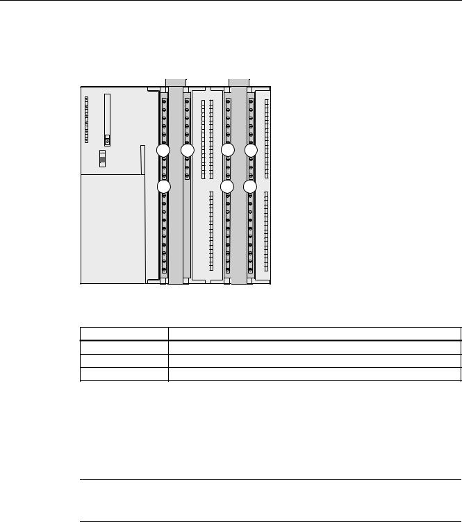
The figure below illustrates the integrated digital and analog I/Os of the CPU with open front covers.
|
|
X11 |
|
X12 |
SF |
|
|
|
|
BF |
|
|
|
|
DC5V |
|
|
|
|
FRCE |
|
|
|
|
RUN |
|
|
|
|
STOP |
|
|
|
|
RUN |
1 |
2 |
2 |
3 |
STOP |
|
|
|
|
MRES |
|
|
|
|
|
1 |
|
2 |
3 |
Figure 2-1 Integrated I/Os of CPU 31xC (CPU 314C-2 PtP, for example)
The figure shows |
the following integrated I/Os |
(1)Analog I/Os
(2)each with 8 digital inputs
(3)each with 8 digital outputs
Slot for the SIMATIC Micro Memory Card (MMC)
A SIMATIC micro memory card (MMC) is used as memory module. You can use MMCs as load memory and as portable storage medium.
Note
These CPUs do not have an integrated load memory and thus require an MMC for operation.
2-2 |
CPU 31xC and CPU 31x, Technical data |
Manual, Edition 08/2004, A5E00105475-05 |

Operating and display elements 2.1 Operating and display elements: CPU 31xC
Mode selector switch
Use the mode selector switch to set the CPU operating mode.
Table 2-1 |
Positions of the mode selector switch |
|
|
|
|
Position |
Meaning |
Description |
RUN |
RUN mode |
The CPU executes the user program. |
STOP |
STOP mode |
The CPU does not execute a user program. |
MRES |
CPU memory |
Mode selector switch position with pushbutton function for CPU |
|
reset |
memory reset. A CPU memory reset by means of mode selector |
|
|
switch requires a specific sequence of operation. |
Reference
•CPU operating modes: STEP 7 Online Help.
•Information on CPU memory reset: Operating instructions CPU 31xC and CPU31x, Commissioning, Commissioning Modules, CPU Memory Reset by means of Mode Selector Switch
•Evaluation of the LEDs upon error or diagnostic event: Operating Instructions CPU 31xC and CPU 31x, Test Functions, Diagnostics and Troubleshooting, Diagnostics with the help of Status and Error LEDs
Power supply connection
Each CPU is equipped with a double-pole power supply socket. The connector with screw terminals is inserted into this socket when the CPU is delivered.
Differences between the CPUs
Table 2-2 |
Differences of the CPUs 31xC |
|
|
|
|
|||
|
|
|
|
|
|
|
|
|
Element |
|
CPU |
CPU |
|
CPU |
CPU |
CPU |
CPU |
|
|
312C |
313C |
|
313C-2 DP |
313C-2 PtP |
314C-2 DP |
314C-2 PtP |
9-pole DP |
|
– |
– |
|
X |
– |
X |
– |
interface (X2) |
|
|
|
|
|
|
|
|
15-pole PtP |
|
– |
– |
|
– |
X |
– |
X |
interface (X2) |
|
|
|
|
|
|
|
|
Digital inputs |
|
10 |
24 |
|
16 |
16 |
24 |
24 |
Digital outputs |
6 |
16 |
|
16 |
16 |
16 |
16 |
|
Analog inputs |
– |
4 + 1 |
|
– |
– |
4 + 1 |
4 + 1 |
|
Analog outputs |
– |
2 |
|
– |
– |
2 |
2 |
|
Technological |
2 counters |
3 counters |
|
3 counters |
3 counters |
4 counters |
4 counters |
|
functions |
|
|
|
|
|
|
1 channel for |
1 channel |
|
|
|
|
|
|
|
positioning |
for |
|
|
|
|
|
|
|
|
positioning |
CPU 31xC and CPU 31x, Technical data |
2-3 |
Manual, Edition 08/2004, A5E00105475-05 |

Operating and display elements
2.1 Operating and display elements: CPU 31xC
2.1.1Status and Error Indicators: CPU 31xC
LED designation |
Color |
Meaning |
SF |
red |
Hardware or software error |
BF (for CPUs with DP |
red |
Bus error |
interface only) |
|
|
DC5V |
green |
5-V power for CPU and S7-300 bus is OK |
FRCE |
yellow |
Force job is active |
RUN |
green |
CPU in RUN |
|
|
The LED flashes during STARTUP at a rate of 2 Hz, and in HOLD |
|
|
state at 0.5 Hz. |
STOP |
yellow |
CPU in STOP and HOLD or STARTUP |
|
|
The LED flashes at 0.5 Hz when the CPU requests a memory reset, |
|
|
and during the reset at 2 Hz. |
Reference
•CPU operating modes: STEP 7 Online Help.
•Information on CPU memory reset: Operating instructions CPU 31xC and CPU31x, Commissioning, Commissioning Modules, CPU Memory Reset by means of Mode Selector SwitchEvaluation of the LEDs upon error or diagnostic event: Operating Instructions CPU 31xC and CPU 31x, Test Functions, Diagnostics and Troubleshooting, Diagnostics with the help of Status and Error LEDs
2-4 |
CPU 31xC and CPU 31x, Technical data |
Manual, Edition 08/2004, A5E00105475-05 |
Operating and display elements 2.2 Operating and display elements: CPU 31x
2.2Operating and display elements: CPU 31x
2.2.1Operating and display elements: CPU 312, 314, 315-2 DP:
Operating and display elements
|
|
1 |
|
|
SF |
|
|
6 |
BF |
|
MMC |
DC5V |
|
||
|
|
||
|
FRCE |
|
|
5 |
RUN |
|
|
STOP |
|
|
|
|
|
|
|
|
|
RUN |
|
|
|
STOP |
|
|
|
MRES |
|
4 |
|
|
2 |
|
X1 |
X2 |
3 |
|
|
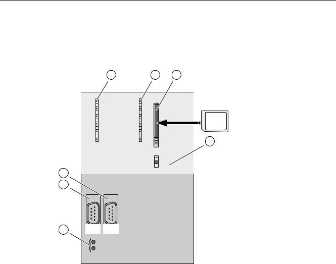
The figures show |
the following CPU elements |
(1) |
Slot for the Micro Memory Card (MMC), incl. the ejector |
(2) |
2. Interface X2 (only for CPU 315-2 DP) |
(3) |
Power supply connection |
(4) |
1. Interface X1 (MPI) |
(5) |
Mode selector switch |
(6) |
Status and error displays |
CPU 31xC and CPU 31x, Technical data |
2-5 |
Manual, Edition 08/2004, A5E00105475-05 |

Operating and display elements
2.2 Operating and display elements: CPU 31x
Slot for the SIMATIC Micro Memory Card (MMC)
A SIMATIC Micro Memory Card (MMC) is used as memory module. You can use MMCs as load memory and as portable storage medium.
Note
These CPUs do not have an integrated load memory and thus require an MMC for operation.
Mode selector switch
The mode selector switch is used to set the CPU operating mode.
Table 2-3 |
Positions of the mode selector switch |
|
|
|
|
Position |
Meaning |
Description |
RUN |
RUN mode |
The CPU executes the user program. |
STOP |
STOP mode |
The CPU does not execute a user program. |
MRES |
CPU memory reset |
Mode selector switch position with pushbutton function for CPU |
|
|
memory reset. A CPU memory reset by means of mode |
|
|
selector switch requires a specific sequence of operation. |
Reference
•CPU operating modes: STEP 7 Online Help.
•Information on CPU memory reset: Operating instructions CPU 31xC and CPU31x, Commissioning, Commissioning Modules, CP Memory Reset by means of Mode Selector Switch
•Evaluation of the LEDs upon error or diagnostic event: Operating Instructions CPU 31xC and CPU 31x, Test Functions, Diagnostics and Troubleshooting, Diagnostics with the help of Status and Error LEDs
Power supply connection
Each CPU is equipped with a double-pole power supply socket. The connector with screw terminals is inserted into this socket when the CPU is delivered.
2-6 |
CPU 31xC and CPU 31x, Technical data |
Manual, Edition 08/2004, A5E00105475-05 |
Operating and display elements 2.2 Operating and display elements: CPU 31x
2.2.2Operating and display elements: CPU 317-2 DP
Operating and display elements
1 |
2 |
3 |
BF1 |
SF |
|
BF2
DC5V |
|
FRCE |
MMC |
|
|
RUN |
|
STOP |
4 |
|
|
|
RUN |
|
STOP |
|
MRES |
7
6
5 |
X1 |
X2 |
|
|
|
|
|
|
|
|
|
|
|
|
|
|
|
|
|
|
|
|
|
|
|
|
|
|
|
|
|
|
|
|
|
|
|
|
The figures show |
|
the following CPU elements |
||||||
(1) |
|
|
|
|
|
Bus error indicator |
||
(2) |
|
|
|
|
|
Status and error displays |
||
(3) |
|
|
|
|
|
Slot for the Micro Memory Card (MMC), incl. the ejector |
||
(4) |
|
|
|
|
|
Mode selector switch |
||
(5) |
|
|
|
|
|
Power supply connection |
||
(6) |
|
|
|
|
|
1. |
Interface X1 |
(MPI/DP) |
(7) |
|
|
|
|
|
2. |
Interface X2 |
(DP) |
CPU 31xC and CPU 31x, Technical data |
2-7 |
Manual, Edition 08/2004, A5E00105475-05 |

Operating and display elements
2.2 Operating and display elements: CPU 31x
Slot for the SIMATIC Micro Memory Card (MMC)
A SIMATIC Micro Memory Card (MMC) is used as memory module. You can use MMCs as load memory and as portable storage medium.
Note
These CPUs do not have an integrated load memory and thus require an MMC for operation.
Mode selector switch
Use the mode selector switch to set the CPU operating mode.
Table 2-4 |
Positions of the mode selector switch |
|
|
|
|
Position |
Meaning |
Description |
RUN |
RUN mode |
The CPU executes the user program. |
STOP |
STOP mode |
The CPU does not execute a user program. |
MRES |
CPU memory reset |
Mode selector switch position with pushbutton function for CPU |
|
|
memory reset. A CPU memory reset by means of mode |
|
|
selector switch requires a specific sequence of operation. |
Reference
•CPU operating modes: STEP 7 Online Help.
•Information on CPU memory reset: Operating instructions CPU 31xC and CPU31x, Commissioning, Commissioning Modules, CP Memory Reset by means of Mode Selector Switch
•Evaluation of the LEDs upon error or diagnostic event: Operating Instructions CPU 31xC and CPU 31x, Test Functions, Diagnostics and Troubleshooting, Diagnostics with the help of Status and Error LEDs
Power supply connection
Each CPU is equipped with a double-pole power supply socket. The connector with screw terminals is inserted into this socket when the CPU is delivered.
2-8 |
CPU 31xC and CPU 31x, Technical data |
Manual, Edition 08/2004, A5E00105475-05 |
Operating and display elements 2.2 Operating and display elements: CPU 31x
2.2.3Operating and display elements: CPU 31x-2 PN/DP
Operating and display elements
1 |
2 |
3 |
BF1 |
SF |
|
BF2
DC5V |
|
MMC |
FRCE |
|
|
RUN |
|
|
STOP |
|
4 |
|
|
|
|
RUN |
|
|
STOP |
5 |
|
MRES |
|
|
|
8
LINK
RX / TX MAC-ADD.:
X1-X2-X3
X4-X5-X6
 6 7 X1
X2
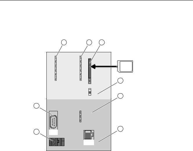
The figures show |
the following CPU elements |
(1) |
Bus error indicators |
(2) |
Status and error displays |
(3) |
Slot for the Micro Memory Card (MMC), incl. the ejector |
(4) |
Mode selector switch |
(5) |
Status display of 2nd interface (X2) |
(6) |
2. Interface X2 (PN) |
(7) |
Power supply connection |
(8) |
1. Interface X1 (MPI/DP) |
CPU 31xC and CPU 31x, Technical data |
2-9 |
Manual, Edition 08/2004, A5E00105475-05 |

Operating and display elements
2.2 Operating and display elements: CPU 31x
Slot for the SIMATIC Micro Memory Card (MMC)
A SIMATIC Micro Memory Card (MMC) is used as memory module. You can use MMCs as load memory and as portable storage medium.
Note
These CPUs do not have an integrated load memory and thus require an MMC for operation.
Mode selector switch
Use the mode selector switch to set the CPU operating mode.
Table 2-5 |
Positions of the mode selector switch |
|
|
|
|
Position |
Meaning |
Description |
RUN |
RUN mode |
The CPU executes the user program. |
STOP |
STOP mode |
The CPU does not execute a user program. |
MRES |
CPU memory reset |
Mode selector switch position with pushbutton function for CPU |
|
|
memory reset. A CPU memory reset by means of mode selector |
|
|
switch requires a specific sequence of operation. |
Reference
•CPU operating modes: STEP 7 Online Help.
•Information on CPU memory reset: Operating instructions CPU 31xC and CPU31x, Commissioning, Commissioning Modules, CP Memory Reset by means of Mode Selector Switch
•Evaluation of the LEDs upon error or diagnostic event: Operating Instructions CPU 31xC and CPU 31x, Test Functions, Diagnostics and Troubleshooting, Diagnostics with the help of Status and Error LEDs
Power supply connection
Each CPU is equipped with a double-pole power supply socket. The connector with screw terminals is inserted into this socket when the CPU is delivered.
2-10 |
CPU 31xC and CPU 31x, Technical data |
Manual, Edition 08/2004, A5E00105475-05 |

Operating and display elements 2.2 Operating and display elements: CPU 31x
2.2.4Status and error displays of the CPU 31x
General status and error displays
Table 2-6 |
General status and error displays of the CPU 31x |
||
|
|
|
|
LED designation |
Color |
Meaning |
|
SF |
|
red |
Hardware or software error. |
DC5V |
|
green |
5-V power for the CPU and the S7-300 bus |
FRCE |
|
yellow |
LED is lit: Active force job |
|
|
|
LED flashes at 2 Hz: Node flash test function (only CPUs with |
|
|
|
firmware V2.2.0 or higher) |
RUN |
|
green |
CPU in RUN |
|
|
|
The LED flashes during STARTUP at a rate of 2 Hz, and in HOLD |
|
|
|
state at 0.5 Hz. |
STOP |
|
yellow |
CPU in STOP, or HOLD, or STARTUP |
|
|
|
The LED flashes at 0.5 Hz when the CPU requests a memory reset, |
|
|
|
and during the reset at 2 Hz. |
Displays for the X1 and X2 interfaces
Table 2-7 |
Bus error displays of CPU 31x |
|
||
|
|
|
|
|
CPU |
|
LED designation |
Color |
Meaning |
315-2 DP |
|
BF |
red |
Bus error at DP interface (X2) |
317-2 DP |
|
BF1 |
red |
Bus error at interface 1 (X1) |
|
|
BF2 |
red |
Bus error at interface 2 (X1) |
31x-2 PN/DP |
|
BF1 |
red |
Bus error at interface 1 (X1) |
|
|
BF2 |
red |
Bus error at interface 2 (X1) |
|
|
LINK |
green |
Active communication at interface 2 (X2). |
|
|
RX/TX |
yellow |
Receive / Transmit data at interface 2 (X2) |
Reference
•CPU operating modes: STEP 7 Online Help.
•Information on CPU memory reset: Operating instructions CPU 31xC and CPU31x, Commissioning, Commissioning Modules, CP Memory Reset by means of Mode Selector Switch
•Evaluation of the LEDs upon error or diagnostic event: Operating Instructions CPU 31xC and CPU 31x, Test Functions, Diagnostics and Troubleshooting, Diagnostics with the help of Status and Error LEDs
CPU 31xC and CPU 31x, Technical data |
2-11 |
Manual, Edition 08/2004, A5E00105475-05 |

Operating and display elements
2.2 Operating and display elements: CPU 31x
2-12 |
CPU 31xC and CPU 31x, Technical data |
Manual, Edition 08/2004, A5E00105475-05 |

Communication |
3 |
3.1Interfaces
3.1.1Multi-Point Interface (MPI)
Availability
All CPUs described in this manual are equipped with an MPI interface X1.
A CPU equipped with an MPI/DP interface is configured and supplied as MPI. To use the DP interface, set DP interface mode in STEP 7.
Properties
The MPI (Multi-Point Interface) represents the CPU interface for PG/OP connections, or for communication on an MPI subnet.
The typical (default) transmission rate of all CPUs is 187.5 kbps. You can also set 19.2 kbps for communication with an S7-200. The 315-2 PN/DP and 317 CPUs support transmission rates up to 12 Mbps.
The CPU automatically broadcasts its bus configuration via the MPI interface (the transmission rate, for example). A PG, for example, can thus receive the correct parameters and automatically connect to a MPI subnet.
Note
You may only connect PGs to an MPI subnet which is in RUN.
Other stations (for example, OP, TP, ...) should not be connected to the MPI subnet while the system is in RUN. Otherwise, transferred data might be corrupted as a result interference, or global data packages may be lost.
CPU 31xC and CPU 31x, Technical data |
3-1 |
Manual, Edition 08/2004, A5E00105475-05 |

Communication
3.1 Interfaces
Devices capable of MPI communication
•PG/PC
•OP/TP
•S7-300 / S7-400 with MPI interface
•S7-200 (19.2 kbps only)
3.1.2PROFIBUS DP
Availability
CPUs with “DP“ name suffix are equipped at least with a DP X2 interface.
The 315-2 PN/DP and 317 CPUs are equipped with an MPI/DP X1 interface. A CPU with MPI/DP interface is supplied with a default MPI configuration. You need to set DP mode in STEP 7 if you want to use the DP interface.
Operating modes for CPUs with two DP interfaces
Table 3-1 |
Operating modes for CPUs with two DP interfaces |
|||
|
|
|||
MPI/DP interface (X1) |
PROFIBUS DP interface (X2) |
|||
• |
MPI |
|
• |
not configured |
• |
DP master |
• |
DP master |
|
• |
DP slave 1 |
• |
DP slave 1 |
|
1 simultaneous operation of the DP slave on both interfaces is excluded
Properties
The PROFIBUS DP interface is mainly used to connect distributed I/O. PROFIBUS DP allows you to create large subnets, for example.
The PROFIBUS DP interface can be set for operation in master or slave mode, and supports transmission rates up to 12 Mbps.
The CPU broadcasts its bus parameters (transmission rate, for example) via the PROFIBUS DP interface when master mode is set. A PG, for example, can thus receive the correct parameters and automatically connect to a PROFIBUS subnet. In your configuration you can specify to disable bus parameter broadcasting.
3-2 |
CPU 31xC and CPU 31x, Technical data |
Manual, Edition 08/2004, A5E00105475-05 |
Loading...