


HP Scitex FB500 /
FB700
Service Manual
*CQ114-90048*
Document part number: CQ114-90035, Rev. B

Table of Contents |
Printer orientation ................................................................................................ |
12 |
|
Required tools ...................................................................................................... |
13 |
|
Parts List for Field Replaceable Modules.................................................. |
14 |
|
Exploded Views...................................................................................... |
31 |
|
Exploded views: Off-head supply assemblies ....................................................... |
31 |
|
OHS part numbers .......................................................................................................................... |
31 |
|
Ink pumps, Exploded view ............................................................................................................... |
32 |
|
Vacuum pump assembly exploded view............................................................................................. |
33 |
|
Vacuum reservoir, Exploded view ..................................................................................................... |
34 |
|
Ink homogenizer, Exploded view ...................................................................................................... |
35 |
|
Exploded views: Carriage assemblies ................................................................... |
36 |
|
Trolley assembly (upper and lower) exploded view ............................................................................. |
36 |
|
Carriage assembly, exploded views .................................................................................................. |
37 |
|
Carriage assembly brackets, exploded view....................................................................................... |
37 |
|
Carriage pen plate, exploded view................................................................................................... |
38 |
|
Carriage reservoirs, exploded views ................................................................................................. |
39 |
|
Printhead interface plate’s alignment pin, exploded view ..................................................................... |
39 |
|
Carriage back plate, exploded view ................................................................................................. |
40 |
|
Carriage side attachments, exploded views........................................................................................ |
41 |
|
Exploded views: Carriage-drive assemblies .......................................................... |
48 |
|
Exploded views: Service station assemblies .......................................................... |
49 |
|
Exploded views: Track assemblies........................................................................ |
52 |
|
Track attachment at carriage ............................................................................................................ |
52 |
|
Exploded views: Media-drive assemblies.............................................................. |
54 |
|
Media-drive assemblies exploded views ............................................................................................ |
54 |
|
Media-drive assemblies part numbers ................................................................................................ |
57 |
|
Exploded views: Media-drive actuator assemblies ................................................ |
58 |
|
Media-drive actuator assemblies exploded views ................................................................................ |
58 |
|
Theory of operation and component identification................................... |
65 |
|
Off-Head Supply Assemblies ................................................................................ |
65 |
|
About the OHS (off-head supply)....................................................................................................... |
65 |
|
About the vacuum assembly ............................................................................................................. |
65 |
|
Vacuum assembly diagram .............................................................................................................. |
66 |
|
Vacuum assembly air flow diagram................................................................................................... |
67 |
|
About the vacuum pump .................................................................................................................. |
68 |
|
About the vacuum regulator ............................................................................................................. |
68 |
|
About the vacuum air-inlet filter......................................................................................................... |
68 |
|
About the vacuum accumulator ......................................................................................................... |
68 |
|
About the vacuum restrictor .............................................................................................................. |
69 |
|
About the vacuum sensor ................................................................................................................. |
69 |
|
About the vacuum assembly power supply ......................................................................................... |
69 |
|
About the pressure pump ................................................................................................................. |
70 |
|
About the pressure sensor ................................................................................................................ |
70 |
|
About the ink pumps........................................................................................................................ |
71 |
|
About the ink-pump check valve........................................................................................................ |
72 |
|
About the permanent ink filters ......................................................................................................... |
72 |
|
About the ink.................................................................................................................................. |
73 |
|
About the tubes............................................................................................................................... |
73 |
|
About the ink boxes ........................................................................................................................ |
73 |
|
About the profilers .......................................................................................................................... |
74 |
|
About the white ink option ............................................................................................................... |
74 |
|
About the ink homogenizer (shaker) .................................................................................................. |
75 |
|
About the ink-box filters ................................................................................................................... |
75 |
|
About the OHS controller................................................................................................................. |
76 |
|
Carriage............................................................................................................... |
76 |
|
Wiring diagram for FB500 Carriage Assembly .................................................................................. |
77 |
|
Wiring diagram for FB700 Carriage Assembly .................................................................................. |
78 |
|
About the carriage head height ........................................................................................................ |
79 |
|
About the lamps.............................................................................................................................. |
79 |
|
About the lamp bulbs ...................................................................................................................... |
80 |
|
About the camera ........................................................................................................................... |
80 |
|
About the air manifold..................................................................................................................... |
81 |
|
About the carriage ink filters............................................................................................................. |
81 |
|
About the printhead reservoirs .......................................................................................................... |
82 |
|
About the thermistors ....................................................................................................................... |
83 |
Part No. CQ114-90035 Rev B |
HP Scitex FB500 / FB700 Service Manual |
Page 1 of 510 |

|
About the vacuum tubes................................................................................................................... |
84 |
|
About the vacuum tubes, split ........................................................................................................... |
84 |
|
About the printheads ....................................................................................................................... |
85 |
|
About the printhead interface plate ................................................................................................... |
86 |
|
About printhead serial numbers ........................................................................................................ |
87 |
|
About printhead y-axis and x-axis positioning..................................................................................... |
87 |
|
About printhead saber angle............................................................................................................ |
87 |
|
About carriage (gross) saber angle ................................................................................................... |
87 |
|
About the carriage headboard ......................................................................................................... |
87 |
|
About the carriage headboard lights ................................................................................................. |
88 |
|
About the encoder reader ................................................................................................................ |
89 |
|
About the carriage home sensor ....................................................................................................... |
89 |
|
About the carriage trolley assembly................................................................................................... |
90 |
|
About the upper carriage trolley assembly ......................................................................................... |
90 |
|
About the lower carriage trolley assembly.......................................................................................... |
90 |
|
Service station...................................................................................................... |
91 |
|
About the service station .................................................................................................................. |
91 |
|
About ink purges ............................................................................................................................ |
91 |
|
About the Shop-Vac ........................................................................................................................ |
91 |
|
About the float Sensor ..................................................................................................................... |
92 |
|
About the service station wipers........................................................................................................ |
93 |
|
About the wiper-carriage home sensor............................................................................................... |
93 |
|
About the gap sensor ...................................................................................................................... |
94 |
|
About the service station access sensor .............................................................................................. |
94 |
|
About the service station actuator (up-down motor).............................................................................. |
94 |
|
About the service station encoder...................................................................................................... |
94 |
|
About the service station encoder reader ........................................................................................... |
95 |
|
About the waste-ink jug.................................................................................................................... |
96 |
|
Carriage-drive...................................................................................................... |
97 |
|
About the carriage-drive assembly .................................................................................................... |
97 |
|
About the carriage-drive smooth pulley .............................................................................................. |
97 |
|
About the carriage-drive shaft........................................................................................................... |
97 |
|
About the carriage-drive timing belt................................................................................................... |
97 |
|
About the carriage-drive motor ......................................................................................................... |
98 |
|
About the Carriage Idler .................................................................................................................. |
98 |
|
About the carriage-drive belt ............................................................................................................ |
98 |
|
About the carriage-drive belt length and tension ................................................................................. |
99 |
|
About the rail strips ......................................................................................................................... |
99 |
|
About the carriage encoder strip..................................................................................................... |
100 |
|
Track assemblies ................................................................................................ |
101 |
|
About the track assembly ............................................................................................................... |
101 |
|
About the ink tubes ....................................................................................................................... |
101 |
|
About the LVDS cable.................................................................................................................... |
102 |
|
About the headboard power cables ................................................................................................ |
102 |
|
About the H-block clamp................................................................................................................ |
102 |
|
Media drive........................................................................................................ |
104 |
|
About the media-drive motor .......................................................................................................... |
104 |
|
About the media-drive motor coupling ............................................................................................. |
104 |
|
About the media-drive motor encoder .............................................................................................. |
105 |
|
About the high-resolution encoder ring............................................................................................. |
105 |
|
About the high-resolution belt encoder reader................................................................................... |
105 |
|
About the media-drive belt ............................................................................................................. |
108 |
|
About the media-drive roller ........................................................................................................... |
108 |
|
About the idler roller ..................................................................................................................... |
109 |
|
About the adjustment bearing block assembly .................................................................................. |
109 |
|
About the vacuum trays ................................................................................................................. |
110 |
|
About the airflow plate .................................................................................................................. |
111 |
|
About the ionizer .......................................................................................................................... |
111 |
|
About the N-up pins ...................................................................................................................... |
111 |
|
About the actuator motors .............................................................................................................. |
112 |
|
About the media alignment bar ...................................................................................................... |
113 |
|
About the input roller..................................................................................................................... |
113 |
|
About the output roller ................................................................................................................... |
114 |
|
About the media thickness sensor.................................................................................................... |
114 |
|
About the media detection sensor ................................................................................................... |
114 |
|
Roll-to-roll ............................................................................................ |
115 |
|
About the roll-to-roll assembly ........................................................................... |
115 |
|
Lift and press foam rollers .............................................................................................................. |
115 |
|
About the supply assemblies........................................................................................................... |
115 |
Part No. CQ114-90035 Rev B |
HP Scitex FB500 / FB700 Service Manual |
Page 2 of 510 |

|
Mid-spool support for heavy media rolls .......................................................................................... |
116 |
|
About the takeup assemblies .......................................................................................................... |
117 |
|
About the limit switches ................................................................................................................. |
118 |
|
Electronics .......................................................................................................... |
119 |
|
Wiring diagram for the FB500 printer ............................................................................................. |
119 |
|
Wiring diagram for FB500 main electronics..................................................................................... |
120 |
|
Wiring diagram for the FB700 printer ............................................................................................. |
121 |
|
Wiring diagram for FB700 main electronics..................................................................................... |
122 |
|
About the main electronics box....................................................................................................... |
123 |
|
Electronics box components identified ............................................................................................. |
123 |
|
About the motor control board........................................................................................................ |
124 |
|
About the 38v/24v power supply ................................................................................................... |
125 |
|
About the AC power distribution board ........................................................................................... |
125 |
|
About the AC filter ........................................................................................................................ |
125 |
|
About the AC relay ....................................................................................................................... |
126 |
|
About the ATX power supply .......................................................................................................... |
126 |
|
About the hard disk....................................................................................................................... |
126 |
|
About the motherboard.................................................................................................................. |
126 |
|
About the UV power supply............................................................................................................ |
126 |
|
About the I/O board..................................................................................................................... |
128 |
|
About the main power cable .......................................................................................................... |
129 |
|
Uninterrupted power supply ........................................................................................................... |
130 |
|
Cable Pinouts ..................................................................................................... |
131 |
|
Troubleshooting printer components ..................................................... |
142 |
|
Troubleshooting carriage-drive assemblies ......................................................... |
142 |
|
Carriage motion failures ................................................................................................................ |
142 |
|
Troubleshooting carriage motion failures.......................................................................................... |
142 |
|
Troubleshooting the carriage-drive smooth pulley .............................................................................. |
144 |
|
Troubleshooting the carriage-drive shaft........................................................................................... |
144 |
|
Troubleshooting the carriage-drive timing belt................................................................................... |
144 |
|
Troubleshooting the carriage-drive motor ......................................................................................... |
144 |
|
Troubleshooting the carriage-drive belt ............................................................................................ |
145 |
|
Troubleshooting the rail strips ......................................................................................................... |
145 |
|
Troubleshooting the carriage encoder strip....................................................................................... |
145 |
|
Troubleshooting Carriage Assemblies ................................................................. |
146 |
|
Troubleshooting carriage head height ............................................................................................. |
146 |
|
Troubleshooting the lamps.............................................................................................................. |
146 |
|
Troubleshooting the camera ........................................................................................................... |
146 |
|
Troubleshooting the air manifold..................................................................................................... |
146 |
|
Troubleshooting the carriage ink filters............................................................................................. |
147 |
|
Troubleshooting printhead reservoirs ............................................................................................... |
147 |
|
Troubleshooting thermistors ............................................................................................................ |
147 |
|
Troubleshooting the vacuum tube .................................................................................................... |
147 |
|
Troubleshooting split vacuum tubes.................................................................................................. |
147 |
|
Troubleshooting printheads ............................................................................................................ |
147 |
|
Troubleshooting the printhead interface plate ................................................................................... |
148 |
|
Troubleshooting the carriage headboard ......................................................................................... |
148 |
|
Troubleshooting the carriage encoder reader ................................................................................... |
148 |
|
Troubleshooting the home sensor .................................................................................................... |
149 |
|
Troubleshooting the upper trolley .................................................................................................... |
149 |
|
Troubleshooting the lower trolley..................................................................................................... |
149 |
|
Troubleshooting the OHS assemblies .................................................................. |
150 |
|
Troubleshooting the vacuum assembly ............................................................................................. |
150 |
|
Troubleshooting the vacuum pump .................................................................................................. |
150 |
|
Troubleshooting the vacuum regulator.............................................................................................. |
150 |
|
Troubleshooting the vacuum accumulator ......................................................................................... |
150 |
|
Troubleshooting the vacuum restrictor .............................................................................................. |
151 |
|
Troubleshooting the vacuum sensor ................................................................................................. |
151 |
|
Troubleshooting vacuum power supply ............................................................................................ |
151 |
|
Troubleshooting the pressure pump ................................................................................................. |
151 |
|
Troubleshooting the ink pumps........................................................................................................ |
151 |
|
Troubleshooting the ink-line check valve ........................................................................................... |
151 |
|
Troubleshooting profilers................................................................................................................ |
152 |
|
Troubleshooting the ink shaker........................................................................................................ |
152 |
|
Troubleshooting ink-box filters......................................................................................................... |
152 |
|
Troubleshooting the OHS controller ................................................................................................. |
152 |
|
Troubleshooting maintenance system ................................................................. |
153 |
|
Troubleshooting the service station .................................................................................................. |
153 |
|
Troubleshooting the printhead wipers .............................................................................................. |
153 |
Part No. CQ114-90035 Rev B |
HP Scitex FB500 / FB700 Service Manual |
Page 3 of 510 |

|
Troubleshooting the service station encoder and encoder reader |
......................................................... 153 |
|
Troubleshooting the waste ink jug ................................................................................................... |
154 |
|
Troubleshooting the track assemblies ................................................................ |
155 |
|
Troubleshooting the track assembly ................................................................................................. |
155 |
|
Troubleshooting the LVDS cable and LVDS error ............................................................................... |
155 |
|
Detecting a damaged LVDS chip..................................................................................................... |
156 |
|
Troubleshooting error: Failed to Program FPGA ................................................................................ |
157 |
|
Troubleshooting the media-drive assemblies....................................................... |
159 |
|
Troubleshooting the media-drive motor coupling ............................................................................... |
159 |
|
Troubleshooting the media-drive motor encoder ................................................................................ |
159 |
|
Troubleshooting the high-resolution media-drive encoder.................................................................... |
159 |
|
Troubleshooting the media-drive belt ............................................................................................... |
160 |
|
Troubleshooting the ionizer ............................................................................................................ |
160 |
|
Troubleshooting the media alignment bar......................................................................................... |
160 |
|
Troubleshooting the rail actuator motor ............................................................................................ |
160 |
|
Troubleshooting the media thickness sensor...................................................................................... |
160 |
|
Troubleshooting the media detection sensor...................................................................................... |
160 |
|
Troubleshooting the supply spool .................................................................................................... |
161 |
|
Troubleshooting the electronic assemblies........................................................... |
162 |
|
Troubleshooting the motor control board .......................................................................................... |
162 |
|
Troubleshooting the I/O board ....................................................................................................... |
162 |
|
Troubleshooting the 38/24v power supply....................................................................................... |
162 |
|
Printer’s Service Menus......................................................................... |
163 |
|
TOOLS > USER CLEANING AND MAINTENANCE.................................................... |
163 |
|
Menu: Maintenance reminders ....................................................................................................... |
163 |
|
Menu: Replace UV lamp bulb or bulbs............................................................................................. |
163 |
|
Menu: Clean rail encoder strip ....................................................................................................... |
163 |
|
Menu: Clean ionizer needles.......................................................................................................... |
163 |
|
Menu: Clean and lube rail strips ..................................................................................................... |
163 |
|
Menu: Clean print head orifice plates.............................................................................................. |
163 |
|
Menu: Clean/lube service station rails............................................................................................. |
163 |
|
Menu: Clean service station wiper .................................................................................................. |
163 |
|
Menu: Clean carriage wheels......................................................................................................... |
164 |
|
Menu: Vacuum bottom of carriage .................................................................................................. |
164 |
|
Menu: Clean carriage home sensor................................................................................................. |
164 |
|
Menu: Replace UV lamp filters........................................................................................................ |
164 |
|
Menu: Clean electronics box filters.................................................................................................. |
164 |
|
Menu: Replace service station wiper................................................................................................ |
164 |
|
Menu: Drain waste from service station............................................................................................ |
164 |
|
Menu: Clean media thickness sensor roller....................................................................................... |
164 |
|
TOOLS > USER DIAGNOSTICS .............................................................................. |
165 |
|
Menu: Carriage motion ................................................................................................................. |
165 |
|
Menu: Rail motion......................................................................................................................... |
165 |
|
Menu: Calibration......................................................................................................................... |
165 |
|
Menu: Verify H2H Y Alignment....................................................................................................... |
165 |
|
Menu: Print quality ........................................................................................................................ |
165 |
|
Menu: Service station .................................................................................................................... |
165 |
|
Vacuum pressure .......................................................................................................................... |
165 |
|
Menu: Hard drive ......................................................................................................................... |
165 |
|
Menu: LVDS ................................................................................................................................. |
165 |
|
Menu: Print diagnostic plot............................................................................................................. |
165 |
|
Menu: Print jet statistics.................................................................................................................. |
166 |
|
Menu: Warnings and actions list .................................................................................................... |
166 |
|
Menu: Error history ....................................................................................................................... |
166 |
|
Menu: Log error history.................................................................................................................. |
166 |
|
Menu: Log system info ................................................................................................................... |
166 |
|
TOOLS > SERVICE PRINTER > DEVICE TESTS........................................................... |
167 |
|
Menu: Device test wizard............................................................................................................... |
167 |
|
Menu: Vacuum fan test .................................................................................................................. |
167 |
|
Menu: Media thickness sensor test .................................................................................................. |
167 |
|
Menu: Rail-height motor test ........................................................................................................... |
168 |
|
Menu: Roller, alignment bar, sensor and switch test .......................................................................... |
168 |
|
Menu: Carriage home sensor test.................................................................................................... |
168 |
|
Menu: Profiler test ......................................................................................................................... |
168 |
|
Menu: Service station tests ............................................................................................................. |
169 |
|
Menu: Cabinet fans test ................................................................................................................. |
169 |
|
Menu: Carriage cooling fan test ..................................................................................................... |
169 |
|
Menu: Ionizer relay test ................................................................................................................. |
170 |
|
Menu: UV lamp test....................................................................................................................... |
170 |
Part No. CQ114-90035 Rev B |
HP Scitex FB500 / FB700 Service Manual |
Page 4 of 510 |

|
Menu: Media motion velocity test.................................................................................................... |
170 |
|
Menu: Test media drive control system............................................................................................. |
171 |
|
TOOLS > SERVICE PRINTER > DEVICE TESTS > IMAGE SENSOR TESTS...................... |
172 |
|
Menu: Visually examine LEDs ......................................................................................................... |
172 |
|
Menu: Whitepoint......................................................................................................................... |
172 |
|
Menu: Take picture of white paper.................................................................................................. |
172 |
|
Menu: Take raw picture of dots ...................................................................................................... |
173 |
|
Menu: Take enhanced picture of dots .............................................................................................. |
173 |
|
TOOLS > SERVICE PRINTER > DEVICE TESTS........................................................... |
174 |
|
Menu: Open loop actuator test ....................................................................................................... |
174 |
|
Menu: Open loop service station test............................................................................................... |
174 |
|
Menu: Pod test.............................................................................................................................. |
174 |
|
Menu: Hard drive file system check ................................................................................................. |
174 |
|
TOOLS > SERVICE PRINTER > PRINT TESTS ............................................................ |
175 |
|
Menu: Print prime bars .................................................................................................................. |
175 |
|
Menu: Print test............................................................................................................................. |
175 |
|
Menu: Belt & rail parallel test ......................................................................................................... |
175 |
|
Menu: Media feed accuracy test, one.............................................................................................. |
175 |
|
Menu: Media feed accuracy test, all ............................................................................................... |
176 |
|
Menu: Horizontal dot accuracy....................................................................................................... |
176 |
|
Menu: Vertical dot accuracy........................................................................................................... |
176 |
|
Menu: Print test page..................................................................................................................... |
176 |
|
Menu: Print faux 662 .................................................................................................................... |
176 |
|
Menu: Comb banding ramps.......................................................................................................... |
176 |
|
TOOLS > SERVICE PRINTER > INK SYSTEM TESTS................................................... |
176 |
|
Menu: Air valves........................................................................................................................... |
176 |
|
Menu: Prime ink pumps ................................................................................................................. |
176 |
|
Menu: Ink pumps .......................................................................................................................... |
177 |
|
Menu: Ink / air thermistors............................................................................................................. |
177 |
|
Menu: Pressure pump .................................................................................................................... |
177 |
|
Menu: Vacuum pump .................................................................................................................... |
177 |
|
Menu: Turn ON / OFF white ink shaker .......................................................................................... |
178 |
|
Menu: Initial ink fill........................................................................................................................ |
178 |
|
Menu: Prep for shipping ................................................................................................................ |
178 |
|
Menu: Disable on-head system ....................................................................................................... |
178 |
|
TOOLS > SERVICE PRINTER > SERVICE CALIBRATIONS ........................................... |
179 |
|
Menu: Calibration wizard.............................................................................................................. |
179 |
|
TOOLS > SERVICE PRINTER > SERVICE CALIBRATIONS > INDIVIDUAL CALIBRATIONS180 |
|
|
Menu: LCD touchscreen calibration ................................................................................................. |
180 |
|
Menu: Head height calibration ....................................................................................................... |
180 |
|
Menu: Media thickness sensor calibration ........................................................................................ |
180 |
|
Menu: Service station calibration .................................................................................................... |
181 |
|
Menu: Input roller home calibration................................................................................................. |
181 |
|
Menu: Output roller home calibration .............................................................................................. |
182 |
|
Menu: Alignment bar home calibration............................................................................................ |
182 |
|
Menu: UV lamps shutter calibration ................................................................................................. |
182 |
|
Menu: Image sensor height & position ............................................................................................. |
183 |
|
Menu: Printhead Y calibration ........................................................................................................ |
183 |
|
Menu: Media feed calibration ........................................................................................................ |
184 |
|
Menu: Manual bidi calibration ....................................................................................................... |
184 |
|
Menu: Auto head X calibration ....................................................................................................... |
185 |
|
Menu: Pin & alignment bar position ................................................................................................ |
185 |
|
Menu: Media sensor position calibration ......................................................................................... |
185 |
|
Menu: Media alignment bar alignment ............................................................................................ |
185 |
|
TOOLS > SERVICE PRINTER > SERVICE CALIBRATIONS ........................................... |
186 |
|
Menu: Invalidate calibration........................................................................................................... |
186 |
|
TOOLS > SERVICE PRINTER > RESET HOME POSITIONS.......................................... |
187 |
|
Menu: Reset carriage home position................................................................................................ |
187 |
|
Menu: Reset rail home position ....................................................................................................... |
187 |
|
Menu: Home service station ........................................................................................................... |
187 |
|
Menu: Home UV shutters................................................................................................................ |
187 |
|
Menu: Home input roller ................................................................................................................ |
188 |
|
Menu: Home output roller .............................................................................................................. |
188 |
|
Menu: Home alignment bar............................................................................................................ |
188 |
|
TOOLS > SERVICE PRINTER .................................................................................. |
189 |
|
Menu: Measure media width.......................................................................................................... |
189 |
|
Menu: Replace printhead............................................................................................................... |
189 |
|
Menu: Fill replaced printhead......................................................................................................... |
189 |
|
Menu: Set head vacuum ................................................................................................................ |
189 |
Part No. CQ114-90035 Rev B |
HP Scitex FB500 / FB700 Service Manual |
Page 5 of 510 |

|
Menu: Reset image sensor.............................................................................................................. |
190 |
|
Menu: Prep for shipping ................................................................................................................ |
190 |
|
Menu: Install shipping restraint ....................................................................................................... |
190 |
|
Menu: Set clock ............................................................................................................................ |
190 |
|
Menu: Raise rail, bar, and rollers.................................................................................................... |
191 |
|
Menu: Restore hard drive to defaults ............................................................................................... |
191 |
|
Menu: Support roll fed: yes ............................................................................................................ |
191 |
|
Menu: Roll fed media control: method a .......................................................................................... |
191 |
|
Menu: Configure warming attns...................................................................................................... |
191 |
|
Menu: Carriage control ................................................................................................................. |
191 |
|
Menu: Show autoH2H Y calibration ................................................................................................ |
192 |
|
Menu: UV current sense method...................................................................................................... |
192 |
|
Menu: Auto printhead service......................................................................................................... |
192 |
|
Error codes, warnings and actions...................................................................... |
193 |
|
Menu: ERRORS............................................................................................................................. |
193 |
|
Menu: ACTIONS .......................................................................................................................... |
194 |
|
Menu: WARNINGS ...................................................................................................................... |
195 |
|
Cleaning and Maintenance.................................................................... |
196 |
|
Schedule of tasks normally completed by printer’s operator ............................... |
196 |
|
Schedule of cleaning and maintenance performed by service provider................ |
197 |
|
Replacing UV lamp filters ............................................................................................................... |
199 |
|
Cleaning the printheads................................................................................................................. |
199 |
|
Clean the electronics box fan filters ................................................................................................. |
202 |
|
Clean and grease the service station wiper slide rails ........................................................................ |
203 |
|
Replace the service station wipers ................................................................................................... |
205 |
|
Clean service station wiper ............................................................................................................ |
206 |
|
Clean and oil rail carriage-wheel strips............................................................................................ |
206 |
|
Clean the rail encoder strip ............................................................................................................ |
208 |
|
Clean carriage wheels................................................................................................................... |
208 |
|
Clean bottom of carriage ............................................................................................................... |
210 |
|
Clean ionizer tips with brush .......................................................................................................... |
211 |
|
Service station empty / close.......................................................................................................... |
212 |
|
Waste-ink jug’s open and closed positions ....................................................................................... |
212 |
|
Clean media thickness sensor roller................................................................................................. |
213 |
|
Clean the carriage home sensor ..................................................................................................... |
213 |
|
Cleaning the high-resolution encoder hub ........................................................................................ |
214 |
|
Replacement of field replaceable modules (FRMs) ................................. |
216 |
|
Managing Power Off Scenarios .......................................................................... |
216 |
|
Enclosures .......................................................................................................... |
217 |
|
Remove the user-end and service-end enclosures ............................................................................... |
217 |
|
Installing the user and service-end enclosure..................................................................................... |
217 |
|
Removing the output-side, user-end belt enclosure.............................................................................. |
218 |
|
Removing the input-side, user-end belt enclosure ............................................................................... |
218 |
|
Removing the light-blocking tray...................................................................................................... |
218 |
|
Installing the light-blocking tray ....................................................................................................... |
219 |
|
Disconnecting the OHS Cabinet...................................................................................................... |
219 |
|
Removing the output-side top door .................................................................................................. |
220 |
|
Installing the output-side top door.................................................................................................... |
222 |
|
Removing a fan from the output-side door ........................................................................................ |
222 |
|
Installing a fan in the output-door .................................................................................................... |
223 |
|
Carriage FRM Assemblies ................................................................................... |
224 |
|
Carriage assembly cover ............................................................................................................... |
224 |
|
Removing printheads ..................................................................................................................... |
224 |
|
Releasing the service station latch ................................................................................................... |
225 |
|
Installing Printheads....................................................................................................................... |
226 |
|
Install the flex cables ..................................................................................................................... |
229 |
|
Post printhead-replacement calibrations ........................................................................................... |
230 |
|
Removing the carriage headboard .................................................................................................. |
230 |
|
Disconnecting the carriage pressure sensor tube ............................................................................... |
230 |
|
Removing the headboard (with mounting plate) ................................................................................ |
231 |
|
Installing the carriage headboard (with mounting plate)..................................................................... |
231 |
|
Headboard cable connection chart ................................................................................................. |
232 |
|
Removing the carriage camera board.............................................................................................. |
233 |
|
Installing the carriage camera board ............................................................................................... |
234 |
|
Removing a thermistor set .............................................................................................................. |
235 |
|
Power off printer and unplug power cords ....................................................................................... |
235 |
|
Removing the printhead reservoir cover ........................................................................................... |
235 |
Part No. CQ114-90035 Rev B |
HP Scitex FB500 / FB700 Service Manual |
Page 6 of 510 |

|
Clamp vacuum tubes to service printhead components....................................................................... |
236 |
|
Installing a thermistor set................................................................................................................ |
237 |
|
Removing the carriage air manifold................................................................................................. |
238 |
|
Removing the pressure and vacuum tube.......................................................................................... |
239 |
|
Installing the carriage air manifold .................................................................................................. |
240 |
|
Removing the carriage encoder reader ............................................................................................ |
240 |
|
Installing the carriage encoder reader ............................................................................................. |
242 |
|
Removing the carriage from the rail................................................................................................. |
242 |
|
Disconnecting the lamp power cables.............................................................................................. |
243 |
|
Disconnecting the ink tube from the ink reservoir............................................................................... |
243 |
|
Remove the trolley attachment bracket ............................................................................................. |
244 |
|
Installing the carriage on the rail..................................................................................................... |
244 |
|
Reconnecting tubes using tube joiner (tube mender)........................................................................... |
245 |
|
Removing the upper trolley plate ..................................................................................................... |
246 |
|
Installing the upper trolley plate ...................................................................................................... |
248 |
|
Removing the home sensor ............................................................................................................. |
249 |
|
Installing the home sensor .............................................................................................................. |
249 |
|
Removing the home sensor flag....................................................................................................... |
250 |
|
Installing the home sensor flag........................................................................................................ |
250 |
|
Carriage Lamp Assemblies.................................................................................. |
251 |
|
Remove the user-end lamp cover ..................................................................................................... |
251 |
|
Installing the user-end lamp cover.................................................................................................... |
252 |
|
Remove the service-end lamp cover ................................................................................................. |
252 |
|
Install the service-end lamp cover .................................................................................................... |
252 |
|
Removing the UV Lamp Bulb........................................................................................................... |
253 |
|
Installing the UV Lamp Bulb ............................................................................................................ |
254 |
|
Removing the Lamp Glass .............................................................................................................. |
255 |
|
Installing the lamp glass................................................................................................................. |
256 |
|
Removing the lamp fan assembly .................................................................................................... |
256 |
|
Installing the lamp fan ................................................................................................................... |
257 |
|
Removing a single lamp fan ........................................................................................................... |
257 |
|
Installing a single lamp fan............................................................................................................. |
258 |
|
Carriage-drive assemblies .................................................................................. |
259 |
|
Releasing the carriage-drive belt tension .......................................................................................... |
259 |
|
Removing the carriage-drive idler.................................................................................................... |
259 |
|
Installing the carriage-drive idler ..................................................................................................... |
259 |
|
Removing the carriage-drive belt..................................................................................................... |
260 |
|
Installing the carriage-drive belt ...................................................................................................... |
260 |
|
Remove the carriage-drive motor..................................................................................................... |
261 |
|
Remove the carriage-drive timing belt .............................................................................................. |
262 |
|
Install the carriage-drive motor........................................................................................................ |
262 |
|
Remove the carriage-drive shaft ...................................................................................................... |
262 |
|
Remove the carriage-drive assembly housing .................................................................................... |
263 |
|
Remove the rail encoder strip ............................................................................. |
264 |
|
Installing the rail encoder strip ........................................................................................................ |
264 |
|
Removing rail wheel strips.............................................................................................................. |
266 |
|
Installing a rail wheel strip ............................................................................................................. |
267 |
|
Media-drive media-drive assemblies .................................................................. |
270 |
|
Removing the high-resolution encoder.............................................................................................. |
270 |
|
Installing the high-resolution encoder ............................................................................................... |
273 |
|
Set the high-resolution encoder’s readhead spacing .......................................................................... |
274 |
|
Aligning the high-resolution encoder................................................................................................ |
275 |
|
Turning off AGC (Automatic Gain Control)....................................................................................... |
276 |
|
Align readhead with AGC turned off............................................................................................... |
277 |
|
High-resolution encoder incremental signal calibration....................................................................... |
278 |
|
Activate high-resolution encoder calibration mode............................................................................. |
279 |
|
Set the reference mark for the high-resolution encoder ....................................................................... |
279 |
|
Turning AGC on for the high-resolution encoder interface .................................................................. |
279 |
|
Removing the media-drive motor ..................................................................................................... |
280 |
|
Loosening the media-drive belt tension............................................................................................. |
280 |
|
Removing the media-drive motor ..................................................................................................... |
283 |
|
Installing the media-drive motor ...................................................................................................... |
284 |
|
Torque conversion......................................................................................................................... |
287 |
|
Tensioning the media-drive belt....................................................................................................... |
288 |
|
Removing the media-drive motor’s encoder ...................................................................................... |
288 |
|
Installing the media-drive motor’s encoder........................................................................................ |
290 |
|
Remove an input roller actuator assembly......................................................................................... |
291 |
|
Install an input actuator assembly.................................................................................................... |
293 |
|
Calibrate the input roller assembly .................................................................................................. |
293 |
|
Remove an alignment bar actuator assembly .................................................................................... |
294 |
Part No. CQ114-90035 Rev B |
HP Scitex FB500 / FB700 Service Manual |
Page 7 of 510 |
Install an alignment bar actuator assembly ....................................................................................... |
295 |
Calibrate the alignment bar............................................................................................................ |
295 |
Replace an output-roller actuator assembly ....................................................................................... |
296 |
Remove the output roller................................................................................................................. |
296 |
Install an output-roller actuator assembly .......................................................................................... |
297 |
Calibrate the output-roller............................................................................................................... |
297 |
Rail exploded views ...................................................................................................................... |
297 |
Remove a rail actuator................................................................................................................... |
298 |
Install a rail actuator assembly........................................................................................................ |
301 |
Removing the optional foot switch...................................................................... |
302 |
Installing the replacement foot switch............................................................................................... |
302 |
Media-drive fan arrays ...................................................................................... |
303 |
Fan array exploded views.............................................................................................................. |
303 |
Removing the output-side vacuum fan array...................................................................................... |
304 |
Installing the output-side vacuum fan array ....................................................................................... |
305 |
Removing the middle vacuum fan array ........................................................................................... |
305 |
Installing the middle vacuum fan array............................................................................................. |
306 |
Removing the input-side fan array ................................................................................................... |
307 |
Installing the input-side fan array..................................................................................................... |
308 |
Replacing a fan-array fan .............................................................................................................. |
309 |
Media-drive belt, Removal.............................................................................................................. |
311 |
Installing the media-drive belt ......................................................................................................... |
318 |
Center the media rollers................................................................................................................. |
320 |
Center the driver roller................................................................................................................... |
320 |
Begin idler roller centering ............................................................................................................. |
321 |
Checking media-drive belt tension................................................................................................... |
321 |
Belt tension specification ................................................................................................................ |
323 |
Make sure media rollers are parallel ............................................................................................... |
324 |
Check belt tracking ....................................................................................................................... |
324 |
Measure roller tracking with a dial indicator .................................................................................... |
325 |
Move the belt using the velocity test................................................................................................. |
325 |
Lap the belt .................................................................................................................................. |
326 |
Media Sensors.................................................................................................... |
327 |
Remove the media thickness sensor ................................................................................................. |
327 |
Install the media thickness sensor .................................................................................................... |
327 |
Calibrate the Media Thickness Sensor ............................................................................................. |
328 |
Remove the media detection sensor................................................................................................. |
328 |
Install the media detection sensor .................................................................................................... |
328 |
Roll-to-roll assemblies ........................................................................................ |
329 |
Fasteners for roll-to-roll assemblies................................................................................................... |
329 |
Optional roll-to-roll box contents...................................................................................................... |
330 |
Installation of optional roll-to-roll kit .................................................................. |
331 |
Required tools .............................................................................................................................. |
331 |
Configure printer for roll-to-roll........................................................................................................ |
331 |
Level the printer ............................................................................................................................ |
331 |
Install the roll-to-roll supply arms...................................................................................................... |
332 |
Roll-to-roll alignment tool configurations ............................................................ |
334 |
Assemble tool for supply and/or takeup spools................................................................................. |
334 |
Roll-to-roll alignment tool configurations for supply and/or takeup....................................................... |
335 |
Roll-to-roll alignment tool configuration for foam rollers ...................................................................... |
335 |
Roll-to-roll alignment tool configurations for foam roller tool configuration............................................. |
335 |
Align the roll-to-roll supply spool........................................................................ |
336 |
Align the service-end supply spool position....................................................................................... |
337 |
Tighten the supply arm turnbuckle bolts............................................................................................ |
341 |
Align the foam roller racks ............................................................................................................. |
342 |
Center the foam rollers between the foam roller collars ...................................................................... |
345 |
Roll-to-roll Takeup.............................................................................................. |
348 |
Remove the output roller................................................................................................................. |
348 |
Set the takeup roller position .......................................................................................................... |
348 |
Tighten the takeup arm’s turnbuckle bolts ......................................................................................... |
350 |
Install the roll-to-roll moveable dancer bar ........................................................................................ |
352 |
Install the fixed bar into the dancer rack .......................................................................................... |
354 |
Takeup motor power ..................................................................................................................... |
355 |
Verify movement of dancer bar....................................................................................................... |
356 |
Verify takeup motor turn-off trigger point .......................................................................................... |
356 |
Verify takeup motor’s turn-on trigger point........................................................................................ |
357 |
Adjusting takeup switch positions.................................................................................................... |
358 |
Install the output roller.................................................................................................................... |
359 |
Loading roll-to-roll media ................................................................................... |
360 |
Part No. CQ114-90035 Rev B |
HP Scitex FB500 / FB700 Service Manual |
Page 8 of 510 |
|
|
|

|
Media loading overview................................................................................................................ |
360 |
|
Prepare the printer ........................................................................................................................ |
361 |
|
Center the media on the supply spool.............................................................................................. |
361 |
|
Initiate LOAD MEDIA from printer’s menu......................................................................................... |
363 |
|
Mid-spool support for heavy media rolls .......................................................................................... |
366 |
|
Electronic assembly FRMs ................................................................................... |
367 |
|
Removing the fan’s air filter ............................................................................................................ |
367 |
|
Installing the fan filter cover............................................................................................................ |
367 |
|
Removing the electronics box covers................................................................................................ |
368 |
|
Installing the electronics box covers................................................................................................. |
368 |
|
Removing the motor control board .................................................................................................. |
368 |
|
Installing the motor control board.................................................................................................... |
370 |
|
Removing the FB 500 ebox UV power output cables ......................................................................... |
370 |
|
Installing the FB 500 ebox UV power output cables........................................................................... |
372 |
|
Removing the ebox ionizer power-out cable ..................................................................................... |
372 |
|
Installing the ebox ionizer power-out cable....................................................................................... |
374 |
|
Removing the ebox ShopVac power-out cable .................................................................................. |
374 |
|
Installing the ebox ShopVac power-out cable.................................................................................... |
376 |
|
Removing the ebox main input-power cable ..................................................................................... |
376 |
|
Installing the ebox main input-power cable....................................................................................... |
378 |
|
Removing the AC distribution board ................................................................................................ |
378 |
|
Installing the AC distribution board ................................................................................................. |
379 |
|
Removing the FB500 UV power supply............................................................................................ |
379 |
|
Installing the FB500 UV power supply ............................................................................................. |
380 |
|
Removing the FB700 UV power supply............................................................................................ |
380 |
|
Installing the FB700 UV power supply ............................................................................................. |
382 |
|
Removing an AC relay................................................................................................................... |
382 |
|
Installing an AC relay.................................................................................................................... |
383 |
|
Removing the IO controller board ................................................................................................... |
383 |
|
Installing the IO controller board..................................................................................................... |
385 |
|
Removing the ebox motherboard .................................................................................................... |
385 |
|
Installing the ebox motherboard...................................................................................................... |
387 |
|
Motherboard BIOS configuration .................................................................................................... |
388 |
|
Removing the ebox hard disk ......................................................................................................... |
390 |
|
Installing the ebox hard disk........................................................................................................... |
390 |
|
Removing the ATX power supply..................................................................................................... |
390 |
|
Installing the ATX power supply ...................................................................................................... |
391 |
|
Removing an electronics box fan..................................................................................................... |
392 |
|
Installing an electronics box inlet fan ............................................................................................... |
392 |
|
Maintenance assemblies..................................................................................... |
393 |
|
Removing the service station........................................................................................................... |
393 |
|
Service station cables .................................................................................................................... |
393 |
|
Service station bolts....................................................................................................................... |
394 |
|
Installing the service station ............................................................................................................ |
394 |
|
Disconnecting the service station drain hose ..................................................................................... |
394 |
|
Install the service station drain hose................................................................................................. |
395 |
|
Installing complete drain hose kit .................................................................................................... |
395 |
|
Remove the service station actuator ................................................................................................. |
398 |
|
Install the service station actuator .................................................................................................... |
398 |
|
Remove the service station wiper motor............................................................................................ |
399 |
|
Install the service station wiper motor............................................................................................... |
399 |
|
OHS assemblies.................................................................................................. |
400 |
|
Tube joiners and plugs .................................................................................................................. |
400 |
|
Removing a permanent ink filter...................................................................................................... |
401 |
|
Cutting the ink tube for removal ...................................................................................................... |
401 |
|
Installing the permanent ink filter..................................................................................................... |
402 |
|
Removing the OHS controller board ................................................................................................ |
402 |
|
Installing the OHS controller board ................................................................................................. |
402 |
|
Adjusting vacuum level .................................................................................................................. |
403 |
|
Track assemblies ................................................................................................ |
405 |
|
Replacing the complete track assembly ............................................................................................ |
405 |
|
Overview..................................................................................................................................... |
405 |
|
Things to do first for track replacement .............................................................. |
406 |
|
Print a prime bar pattern................................................................................................................ |
406 |
|
Access the password protected service menu.................................................................................... |
406 |
|
Empty the carriage of ink ............................................................................................................... |
406 |
|
Remove both endcap enclosures ..................................................................................................... |
406 |
|
Included fasteners, plugs and joiners.................................................................. |
407 |
|
Included tube joiners and plugs for track replacement........................................................................ |
407 |
|
Included fasteners for track replacement .......................................................................................... |
407 |
Part No. CQ114-90035 Rev B |
HP Scitex FB500 / FB700 Service Manual |
Page 9 of 510 |
|
Prepare the replacement track............................................................................ |
408 |
|
Cut off unneeded ends of ink tubes on new track .............................................................................. |
408 |
|
Cut off unneeded ends of ink tubes at carriage-end of new track......................................................... |
409 |
|
Install tube joiners into both ends of new ink tubes ............................................ |
409 |
|
Install tube joiners into the user-end of all six ink tubes ....................................................................... |
409 |
|
Label tubes connected to original track that will remain in printer ...................... |
410 |
|
Label tubes that connect to permanent ink filters................................................................................ |
411 |
|
Power off the printer and remove power cords .................................................. |
411 |
|
Power off the printer...................................................................................................................... |
411 |
|
Unplug the main power cable......................................................................................................... |
412 |
|
Disconnecting all track cables and tubes from carriage ....................................... |
413 |
|
Disconnect cables from the carriage................................................................................................ |
413 |
|
Remove the carriage cover............................................................................................................. |
413 |
|
Disconnect cables from the headboard ............................................................................................ |
413 |
|
Disconnect tubes from the carriage.................................................................................................. |
414 |
|
Removing the air tubes from the air manifold.................................................................................... |
416 |
|
Remove the track from the carriage.................................................................... |
417 |
|
Remove the trolley attachment bracket ............................................................................................. |
417 |
|
Removing the track from the rail-attachment bracket .......................................................................... |
417 |
|
Clean area under track....................................................................................... |
418 |
|
Installing the new track assembly onto the rail................................................... |
418 |
|
Attaching the track bracket to the rail .............................................................................................. |
419 |
|
Disconnecting and connecting the user-end of the track assembly ....................... |
419 |
|
Cutting and connecting air tubes......................................................................... |
420 |
|
Cutting the vacuum tube ................................................................................................................ |
420 |
|
Cutting the pressure tube................................................................................................................ |
421 |
|
Cutting and connecting user-end ink tubes one at a time .................................... |
421 |
|
Connect the new track to the ink-pump tubes .................................................................................... |
423 |
|
Disconnecting user-end cables ............................................................................ |
423 |
|
Disconnect the remaining track cables ............................................................................................. |
423 |
|
Cable looms ....................................................................................................... |
425 |
|
Loom for LVDS and headboard power cables ................................................................................... |
425 |
|
Ink and air tube cable looms .......................................................................................................... |
425 |
|
Connecting the track assembly to the carriage.................................................... |
428 |
|
Connect track ink tubes to carriage ink tubes.................................................................................... |
429 |
|
Resolution for too-short tubes............................................................................. |
430 |
|
Extending the track tubes if too short ............................................................................................... |
430 |
|
Connecting the headboard cables ....................................................................... |
430 |
|
Check for grounding strap.................................................................................. |
431 |
|
Install the user-end grounding strap ................................................................................................. |
432 |
|
Installing the service-end grounding strap......................................................................................... |
433 |
|
Powering up the printer ..................................................................................... |
434 |
|
Connect the power cables.............................................................................................................. |
434 |
|
Fill the printheads with ink ................................................................................. |
435 |
|
Finishing up track replacement ........................................................................... |
435 |
|
Drain and clean the service station.................................................................................................. |
435 |
|
Print a prime bar pattern................................................................................................................ |
435 |
|
Replacing an ink tube bundle ............................................................................. |
436 |
|
Ink tube replacement overview........................................................................................................ |
436 |
|
Ink tube bundle replacement, first things ............................................................ |
437 |
|
Print a prime bar pattern................................................................................................................ |
437 |
|
Access the password protected service menu.................................................................................... |
437 |
|
Empty the carriage of ink ............................................................................................................... |
437 |
|
Remove both endcap enclosures ..................................................................................................... |
437 |
|
Prepare the new tube bundle for replacement .................................................... |
437 |
|
Tape the braided cover to the tubes ................................................................................................ |
437 |
|
Cut off end sections of ink tubes in new tube bundle.......................................................................... |
438 |
|
Install tube joiners into the OHS-end of all six tubes........................................................................... |
438 |
|
Label tubes that will be cut but will remain in printer.......................................... |
438 |
|
Label tubes that connect to permanent ink filters................................................................................ |
439 |
|
Power off printer and remove power cables ..................................................................................... |
439 |
|
Disconnect tubes from the carriage.................................................................................................. |
439 |
|
Cutting ink tubes at carriage for tube bundle replacement .................................................................. |
440 |
|
Plug tube that is being removed ...................................................................................................... |
441 |
|
Connect the new tube bundle to the original tube bundle.................................... |
441 |
|
Release the H-block tube clamp at carriage end................................................................................ |
442 |
|
Release the mid-rail cable clamp..................................................................................................... |
442 |
|
Connect the new and original tube bundles together ......................................................................... |
443 |
Part No. CQ114-90035 Rev B |
HP Scitex FB500 / FB700 Service Manual |
Page 10 of 510 |
Connect the power cables.............................................................................................................. |
444 |
Fill the printheads with ink.............................................................................................................. |
444 |
Drain and clean the service station.................................................................................................. |
444 |
Print a prime bar pattern................................................................................................................ |
445 |
Miscellaneous..................................................................................................... |
446 |
Installing Firmware ........................................................................................................................ |
446 |
FTPing to the printer ...................................................................................................................... |
447 |
Manually FTPing the software BIN to the printer’s hard disk................................................................ |
448 |
Accessing the password protected service menu ................................................. |
449 |
Calibrations .......................................................................................... |
450 |
Carriage and printhead calibrations ................................................................... |
450 |
Printhead y-axis calibration ............................................................................................................ |
450 |
Examine the H2H Y Pattern ............................................................................................................ |
451 |
Adjusting the printhead y-axis position............................................................................................. |
454 |
Measure H2H Y Offsets ................................................................................................................. |
458 |
Run the auto BIDI calibration .......................................................................................................... |
460 |
Calibrate the printhead saber angle ................................................................................................ |
460 |
Checking carriage front-to-back tilt .................................................................................................. |
462 |
Calibrating Carriage Front-To-Back Tilt............................................................................................. |
463 |
Front-to-back calibration of the service-end of the carriage ................................................................. |
464 |
Front-to-back calibration of the user-end of the carriage ..................................................................... |
464 |
Calibrate the media-thickness sensor ............................................................................................... |
465 |
Calibrate the camera focus ............................................................................................................ |
465 |
Fixing Carriage Twist .................................................................................................................... |
466 |
Verifying the gross saber angle....................................................................................................... |
467 |
Changing the Carriage Saber Angle ............................................................................................... |
468 |
Head height calibration ................................................................................................................. |
470 |
Reconnect the door-open switch ...................................................................................................... |
474 |
Maintenance calibrations.................................................................................... |
475 |
Calibrating the service station wipers .............................................................................................. |
475 |
Calibrating Wiper Height .............................................................................................................. |
475 |
Calibrating wiper y-axis alignment .................................................................................................. |
475 |
Calibrating wiper left/right tilt ........................................................................................................ |
476 |
Check output-side wiper tilt............................................................................................................. |
476 |
Check input-side wiper tilt .............................................................................................................. |
478 |
Check the wiper height on the input side of the carriage.................................................................... |
478 |
Calibrating wiper x-axis alignment .................................................................................................. |
478 |
Leveling the printer ............................................................................................ |
480 |
Install the printer’s wheels .............................................................................................................. |
480 |
Check height difference between user and service-end of printer......................................................... |
480 |
Check height difference between input and output-side of printer ........................................................ |
481 |
Adjusting leveling pads.................................................................................................................. |
481 |
Remove printer wheels................................................................................................................... |
482 |
Attaching and Leveling the tables ....................................................................... |
482 |
Set table-to-belt distance................................................................................................................. |
485 |
Special Tools......................................................................................... |
486 |
Carriage and printhead special tools .................................................................. |
486 |
Long hex wrench to set y-axis ......................................................................................................... |
486 |
Torque screwdriver and bit set........................................................................................................ |
486 |
Gross saber angle dial indicator..................................................................................................... |
486 |
Vacuum tube clamps ..................................................................................................................... |
487 |
L-shaped ratchet screwdriver........................................................................................................... |
487 |
Tube cutter ................................................................................................................................... |
487 |
Media-drive special tools.................................................................................... |
488 |
Torque wrench for media-drive motor coupling ................................................................................. |
488 |
High-resolution readhead alignment tool .......................................................................................... |
488 |
Dial indicator for high-resolution encoder hub................................................................................... |
488 |
Ionizer point cleaning brush ........................................................................................................... |
489 |
Alcohol swabs .............................................................................................................................. |
489 |
Dial indicator belt tensioning tool.................................................................................................... |
489 |
Roll-to-roll alignment tool ................................................................................................................ |
490 |
C-ring pliers ................................................................................................................................. |
490 |
Calipers....................................................................................................................................... |
490 |
Flexible tape measure.................................................................................................................... |
491 |
Index.................................................................................................... |
492 |
Part No. CQ114-90035 Rev B |
HP Scitex FB500 / FB700 Service Manual |
Page 11 of 510 |
|
|
|
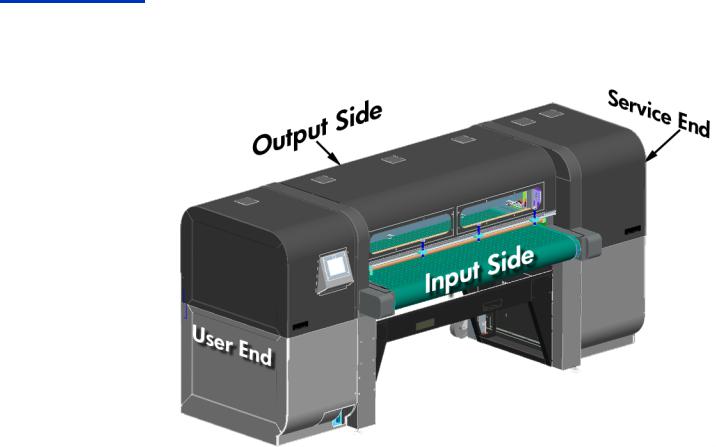
Printer orientation This manual often refers to the following four printer locations: the user end, the service end, the input side and the output side.
Fig. 1. Orientation
Part No. CQ114-90035 Rev B |
HP Scitex FB500 / FB700 Service Manual |
Page 12 of 510 |
|
|
|

Required tools
Each procedure lists the tools required to complete the task. Below are a list of tools commonly used to service the printer. Additional “special tools” (some that must be ordered as service tools) are listed in the section “Special Tools” on page 486.
•Gloves, such as latex
•Protective eye wear
•Paper towels
•Apron to protect clothing from ink
•Drop cloth to protect floor from dripping ink
•Metric sockets from 10 mm - 17 mm
•Socket extensions (8 cm and 20 cm or 3-in and 8-in)
•Metric open-end wrenches (set)
•5/8-in open-end wrench (service station drain replacement)
•Metric hex wrench (such as Allen wrench hex keys) set 2 mm - 8 mm (including 2.5 mm and a 3 mm L-shaped)
•3/32-in hex wrench (carriage calibration)
•1/16-in or a 1.5 mm hex wrench (to loosen the screw that secures the encoder wheel to the shaft of the media-drive motor).
•#1 and #2 phillips screwdriver (including a ten-inch #2 and a short #2)
•Flat-blade screwdriver
•10 X Lighted Loupe (y-axis calibration)
•Flexible tube clamps, such as hemostat clamps (minimum of two clamps for any printhead work).
•Large adjustable wrench, such as a Crescent wrench (for media-drive belt tension)
•Medium-sized adjustable wrench, such as a Crescent wrench
•Internal C-ring pliers (removing c-ring from input-side media-drive bearings - see Fig. 695. on page 490)
•Calipers (used with media-drive belt calibration - see Fig. 696. on page 490)
•Razor knife
•Needle-nosed pliers (lamp fan replacement)
•Head height gauge (ships in accessory box with each printer)
•Long level (1 meter or about 3 feet)
•Short level (30 cm about 1 foot)
•Low-adhesive tape, such as painter’s tape
•Flashlight
•Dial indicator (see special tools on page 487).
Part No. CQ114-90035 Rev B |
HP Scitex FB500 / FB700 Service Manual |
Page 13 of 510 |
|
|
|

Parts List for Field Replaceable Modules
The follow part numbers are the orderable parts for service procedures. Replacement instructions for these parts can be found on the page numbers listed to the right of the part number descrip-
tion.
Table 1: FRM (Field Replaceable Module) List
Part # |
Part Name |
Type |
Description |
Page |
|
|
|
|
|
3160-4231 |
GUARD,FIN- |
Elec |
This is the 92.2mm fan guard with integrated filter holder. Used on |
page 367 |
|
GER,FAN,92.2MM |
|
the main electronics box intake fan. This kit contains one filter |
|
|
SQ,30PPI FILTER |
|
holder with filter media included. |
|
|
|
|
|
|
8120-6895 |
PWR-CORD OPT-N/S 3- |
Elec |
This is the power cord that has no plug. The three wires are |
page 129 |
|
COND 4.5-M-LG ROHS |
|
exposed for attachment of local plug or wiring directly to the facil- |
|
|
|
|
ity circuit. |
|
|
|
|
|
|
8120-6899 |
PWR-CORD OPT-902 3- |
Elec |
'This is the IEC 60309, 16/20 Amp, 250 V, 3 pin, single phase |
page 129 |
|
COND 4.5-M-LG ROHS |
|
European power cable. This power cord plugs into a IEC 6030 9, |
|
|
|
|
16/20 Amp, 250 V, 3 pin, single phase wall outlet |
|
|
|
|
|
|
8120-6903 |
PWR-CORD OPT-930 3- |
Elec |
'The North America/Japan power cable is rated to handle 16 |
page 129 |
|
COND 4.5-M-LG ROHS |
|
amps at a nominal 220 VAC. This power cord plugs into a NEMA |
|
|
|
|
L6-20 wall receptacle. |
|
|
|
|
|
|
0500014 |
ASSY,CBL,HAM- |
Elec |
This is the braided ribbon cable from OHS board to I/O board. |
page 402 |
|
MERHD,OHS_DATA |
|
Common to 500-700, FB910, FB950. |
|
|
|
|
|
|
0500148 |
ASSY,CBL,HEADBD- |
Elec |
This is the cable between the carriage headboard and the UV |
page 243 |
|
UV_HSNG_CTRL |
|
lamps. Qty. 2 are used on the printer; this is the part number for |
|
|
|
|
Qty 1. Common to 500-700, FB950, H-Series. |
|
|
|
|
|
|
0505984 |
ASSY,CBL,HEADBD- |
Carr |
This go/no-go gauge is used to set the carriage (rail) height to |
page 471 |
|
UV_HSNG_CTRL |
|
0.085" above the surface of the media. |
|
|
|
|
|
|
0507663-301 |
ASSY,PROFILER,ANA- |
OHS |
Ink profiler for Cyan (3L) |
page 74 |
|
CONDA,CYAN |
|
|
|
|
UV_CURE,3_LTR |
|
|
|
|
|
|
|
|
0507663-302 |
ASSY,PROFILER,ANA- |
OHS |
Ink profiler for Magenta (3L) |
page 74 |
|
CONDA,MAGENTA |
|
|
|
|
UV_CURE,3_LTR |
|
|
|
|
|
|
|
|
0507663-303 |
ASSY,PROFILER,ANA- |
OHS |
Ink profiler for Yellow (3L) |
page 74 |
|
CONDA,YELLOW |
|
|
|
|
UV_CURE,3_LTR |
|
|
|
|
|
|
|
|
0507663-304 |
ASSY,PROFILER,ANA- |
OHS |
Ink profiler for Black (3L) |
page 74 |
|
CONDA,BLACK |
|
|
|
|
UV_CURE,3_LTR |
|
|
|
|
|
|
|
|
0507663-305 |
ASSY,PROFILER,ANA- |
OHS |
Ink profiler for Light Cyan (3L) |
page 74 |
|
CONDA,LT_CYAN |
|
|
|
|
UV_CURE,3_LTR |
|
|
|
|
|
|
|
|
0507663-306 |
ASSY,PROFILER,ANA- |
OHS |
Ink profiler for Light Magenta (3L) |
page 74 |
|
CONDA,LT_MAG |
|
|
|
|
UV_CURE,3_LTR |
|
|
|
|
|
|
|
|
0507774 |
FLAG,RAIL,ANA- |
Carr |
Home sensor flag that attaches to the rail at the service end. Com- |
page 249 |
|
CONDA,SENSOR_HOME |
Drv |
mon to 500-700 and FB950. |
|
|
|
|
|
|
0602834 |
HAN- |
Encl |
Recessed plastic hand-hold as used in the enclosures for FB910 |
|
|
DLE,FLUSH,PANEL_MOUN |
|
and FB950, FB500 and FB700. |
|
|
T,SNAP_IN |
|
|
|
|
|
|
|
|
Part No. CQ114-90035 Rev B |
HP Scitex FB500 / FB700 Service Manual |
Page 14 of 510 |
|
|
|
Table 1: FRM (Field Replaceable Module) List
Part # |
Part Name |
Type |
Description |
Page |
|
|
|
|
|
0603114 |
FUN- |
OHS |
This is the funnel to facilitate emptying ShopVac waste ink into |
|
|
NEL,32_OZ,6.5"_TOP_OD |
|
waste ink bottle |
|
|
,0.625"_SPOUT_OD,HDPE |
|
|
|
|
|
|
|
|
0900710 |
FRM,BLT,CARRDRV_TIMN |
Carr |
This is the carriage-drive timing belt between the carriage-drive |
page 262 |
|
G,MXABCDHIJ |
Drv |
motor and the carriage-drive shaft. |
|
|
|
|
|
|
0901389 |
FRM,MTR_CNTRL_BRD,L |
Elec |
This is the motor control board (a.k.a. motor driver board) in the |
page 368 |
|
|
|
electronics assembly. Common to 500-700, FB910, FB950. |
|
|
|
|
|
|
0901400 |
FRM,BLWR,BLT_VAC,L |
Maint |
This is the belt vacuum blower assembly used to suck down the |
page 309 |
|
|
|
media to the belt. This includes one blower. Common to 500-700, |
|
|
|
|
FB950, FB910. |
|
|
|
|
|
|
0901402 |
FRM,ALGN_PIN_ASSY,L |
Med |
Alignment pins or N-up pins. These pins used to set the position of |
|
|
|
Drv |
multiple sheets. Multiple instances are used on the printer; this FRM |
|
|
|
|
is for qty. 1. Common to 500-700, FB950, FB910. |
|
|
|
|
|
|
0901405 |
FRM,PRNTER_LVLING_PAD |
Encl |
This is the leveling pad for FB500, FB700, FB950 and FB910 |
|
|
,L |
|
(CS9840). |
|
|
|
|
|
|
0901406 |
FRM,MEDIA_THKNSS_SN |
Med |
This is the media thickness sensor assembly for FB950, FB910, |
page 327 |
|
SR,L |
Drv |
FB500, FB700. It was calibrated in the factory. |
|
|
|
|
|
|
0901407 |
FRM,MEDIADRV_ENCDR,L |
Med |
This is the encoder that attaches to end of the media-drive motor |
page 288 |
|
|
Drv |
on the service end of the printer. Common to 500-700, FB950, |
|
|
|
|
FB910. This is not the hi-resolution encoder located on the user end |
|
|
|
|
of the printer (the type & location varies by the printer model). |
|
|
|
|
|
|
0901425 |
FRM,RLD_E_STRP&FM,ABC |
Carr |
This is the mylar encoder strip (and foam tape) that is installed in |
page 264 |
|
DHIJ |
Drv |
the full length of the rail. It is long enough for a 98"/2.5m printer |
|
|
|
|
and can be trimmed down for smaller printers. This FRM requires |
|
|
|
|
you to reuse the existing aluminum bar from the old strip. |
|
|
|
|
|
|
0901469 |
FRM,ON_OFF_SW,L |
Elec |
This is the On/Off switch on the electronics assembly. Common to |
|
|
|
|
500-700, FB950, FB910. |
|
|
|
|
|
|
0901507 |
'FRM,SPLY,UV_POWER,DU |
Elec |
This is the UV Power Supply for FB500. Also used in some models |
page 379 |
|
AL_CH,N |
|
of the H-Series or CS5400 printer. Check control panel System |
|
|
|
|
Information; if panel shows "NDP", order this FRM. The FRM is a |
|
|
|
|
single unit that powers both channels. See CQ115-67004 for the |
|
|
|
|
FB700 UVPS. |
|
|
|
|
|
|
0901512 |
FRM,PWR_DIST_BRD,N |
Elec |
This is the power distribution board for FB500, FB700, and H- |
page 378 |
|
|
|
Series. This routes inbound AC to the various printer power sup- |
|
|
|
|
plies. |
|
|
|
|
|
|
0901513 |
FRM,FAN,EBOX,COOL- |
Elec |
This fan assembly cools the electronics box in the printer. The elec- |
page 392 |
|
ING,N |
|
tronics box has three of these (fans) in it. Two are exhaust and one |
|
|
|
|
is intake. |
|
|
|
|
|
|
0901533 |
FRM,MTR,SRV_STN,N |
Maint |
This is the service station wiper motor (which moves the wiper |
page 399 |
|
|
|
head in the Y axis). Common to 500-700, FB950, H-Series. |
|
|
|
|
|
|
0901561 |
FRM,S&T_MOTOR&SWITC |
Med |
This is the takeup motor and switch assembly for the roll-to-roll |
page 348 |
|
HES,L |
Drv |
accessory. Common to 500-700, FB910, FB950. |
|
|
|
|
|
|
0901572 |
KIT,TOOL,BELT_TENSION,L |
Med |
This is the custom HP tool/fixture used to measure and set tension |
page 288 |
|
|
Drv |
on the media belt. A dial indicator (not included, see CQ114- |
|
|
|
|
67176) is required to use this tool. Applicable to 500-700, FB950, |
|
|
|
|
FB910. This tool and a dial indicator are mandatory tools for all |
|
|
|
|
service that involves changing the belt tension. |
|
|
|
|
|
|
Part No. CQ114-90035 Rev B |
HP Scitex FB500 / FB700 Service Manual |
Page 15 of 510 |
|
|
|
Table 1: FRM (Field Replaceable Module) List
Part # |
Part Name |
Type |
Description |
Page |
|
|
|
|
|
0901586 |
FRM,AC-RELAY,N |
Elec |
This is the AC Relay that is located in the main electronics box. |
page 382 |
|
|
|
There are multiple instances in the printer; this FRM is for qty. 1 |
|
|
|
|
|
|
0901594 |
FRM,LAMP,GLASS,N |
Carr |
This is the quartz lamp glass that inserts below the left or right |
page 255 |
|
|
|
lamp housing. Common to 500-700, FB950, H-Series. |
|
|
|
|
|
|
0901596 |
FRM,FAN,UV_LAMP,N |
Carr |
This is the cooling fan which is used in the lamp assembly. Each |
page 256 |
|
|
|
lamp has quantity 2. This part number replaces 0500164. |
|
|
|
|
|
|
0901599 |
FRM,ASSY,FAN,N |
Encl |
This is the fan which is used on the top enclosure and end enclo- |
|
|
|
|
sures for FB500, FB700, also H-Series. There are multiple instances |
|
|
|
|
on each printer; this FRM is for qty. 1 |
|
|
|
|
|
|
0970811 |
FRM,MTR,CARRDRV,SFEM |
Carr |
Carriage-drive motor only. |
page 261 |
|
XABCDHIJ ROHS |
Drv |
|
|
|
|
|
|
|
|
|
|
|
|
CH104-67002 |
FRM,N,PUMP,PRESSURE |
OHS |
This pressure pump is for the ink delivery system (IDS) vacuum/ |
|
|
|
|
pressure system. It is located on the OHS assembly. |
|
|
|
|
|
|
CH154-00009 |
BRKT,RAIL,ANA- |
Med |
This bracket attaches the ionizer bar to the back of the rail. It is |
|
|
CONDA,IONIZER |
Drv |
used on the FB500 and the FB950. Multiple instances are used on |
|
|
|
|
the respective printer platforms; this FRM is for qty. 1 |
|
|
|
|
|
|
CH154-50005 |
ASSY,CBL,ANA- |
Elec |
This is the AC power cable from the electronics assembly to the ser- |
|
|
CONDA,SHOP_VAC_EXT, |
|
vice station ShopVac. Commonly used in the 500-700, and the |
|
|
15FT |
|
FB950. |
|
|
|
|
|
|
CH154-60027 |
ASSY,PIGTAIL,OHS,ANA- |
OHS |
This is the replacement "pigtail" tubing/filter/connector assembly |
|
|
CONDA,1.75IN_DIA_FLT |
|
found on the 3-Liter CMYK-LtC-LtM ink cartridges (ink boxes). Com- |
|
|
|
|
monly used in the 500-700 and the FB950. |
|
|
|
|
|
|
CH154-67005 |
FRM,ENCDR_STRIP_ACTU |
Med |
Lifting encoder strip assembly, including bracket, used in all lifting |
page 294 |
|
ATOR,Q |
Drv |
assemblies and service station on the FB950, and all lifting assem- |
|
|
|
|
blies but the service station FB500 and FB700. For the equivalent |
|
|
|
|
service station part in FB500/700, see CQ114-67083. |
|
|
|
|
|
|
CH154-67006 |
FRM,READER,ENCDR,ACT |
Med |
This is the encoder reader board assembly used at all of the lifting |
page 294 |
|
UATOR,Q |
Drv |
positions on the FB950 and FB500 and FB700 printer. This |
|
|
|
|
includes the board only, no metal bracket included. |
|
|
|
|
|
|
CH154-67008 |
FRM,MEDIA_MTR/ |
Med |
This is the media drive motor/reducer assembly for FB950 and |
page 283 |
|
REDCR,Q |
Drv |
FB500 and FB700. It is not the same as the one used on the |
|
|
|
|
FB910. |
|
|
|
|
|
|
CH154-67009 |
FRM,CBL,UV_LAMP,5.3M, |
Carr |
This is the UV lamp power cable in the track from electronics |
page 425 |
|
Q |
|
assembly to one lamp. Two cables are used per printer; this FRM is |
|
|
|
|
for qty. 1. Commonly used in the 500-700, and FB950. |
|
|
|
|
|
|
CH154-67012 |
FRM,ENCLOSURE_WIND |
Encl |
This is the replacement UV-blocking windows used only on the cen- |
|
|
OW,Q |
|
ter output-side door. includes push nuts. Commonly used in the |
|
|
|
|
500-700 and the FB950. See CQ114-67090 for input-side win- |
|
|
|
|
dows. |
|
|
|
|
|
|
CH154-67014 |
FRM,BOT- |
OHS |
This is the 1-gallon bottle with warning label for collection of UV |
page 212 |
|
TLE,UV_WASTE,Q |
|
liquid wastes. |
|
|
|
|
|
|
CH154-67015 |
FRM,BOTTLE,FLUSH,Q |
Misc |
This is the squeeze bottle with label for UV flush. |
|
|
|
|
|
|
CH154-67023 |
FRM,TUBE,VAC- |
Track |
Long tube for ink-system vacuum that runs through the track assy. |
page 420 |
|
UUM,LONG,Q |
|
Common to 500-700, FB950. |
|
|
|
|
|
|
Part No. CQ114-90035 Rev B |
HP Scitex FB500 / FB700 Service Manual |
Page 16 of 510 |
|
|
|
Table 1: FRM (Field Replaceable Module) List
Part # |
Part Name |
Type |
Description |
Page |
|
|
|
|
|
CH154-67024 |
FRM,TUBE,SOL_PRS,LONG |
Track |
Long tube for ink system air pressure that runs through the track |
page 420 |
|
,Q |
|
assy. Common to 500-700, FB950. |
|
|
|
|
|
|
CH154-67037 |
FRM,foot switch/CBL,NO |
Med |
This is the replacement foot switch only, no orange safety hood |
page 302 |
|
HOOD,GRNDED,Q |
Drv |
included, for FB700, FB950, FB910 and H-Series. This accessory is |
|
|
|
|
not supported on the FB500. |
|
|
|
|
|
|
CH231A |
HP,DJ_H35000/ |
Carr |
This is the replacement UV bulb for the H-Series, the FB950, and |
page 253 |
|
DJ_H45000,UV,REPLACE- |
|
the FB500. |
|
|
MENT,BU |
|
|
|
|
|
|
|
|
CH971-62824 |
RULER,ADHESIVE_BACKED |
Med |
This is the ruler located with the N-up alignment pins. The part is |
|
|
,ENGLISH_METRIC,NAR |
Drv |
98"/2.5m long and can be cut down for the 64"/1.6m size |
|
|
|
|
|
|
CQ114-00067 |
ENCL,PRINTER,KAA,USER |
Encl |
This is the user-end endcap. This is the sheet metal enclosure only, |
page 217 |
|
|
|
nothing else. Common to 500-700. |
|
|
|
|
|
|
CQ114-00068 |
ENCL,PRINTER,KAA,SER- |
Encl |
This is the service-end endcap. This is the sheet metal enclosure |
page 217 |
|
VICE |
|
only, nothing else. Common to 500-700. |
|
|
|
|
|
|
CQ114-00072 |
ENCL,PRINTER,KAA,BLT_C |
Encl |
This is the belt cover enclosure on the service end, output side of |
page 218 |
|
VR,OUTPUT,SERVICE |
|
the printer. Common to 500-700. |
|
|
|
|
|
|
CQ114-00073 |
ENCL,PRINTER,KAA,BLT_C |
Encl |
This is the belt cover enclosure on the user end, output side of the |
page 218 |
|
VR,OUTPUT,USER |
|
printer. Common to 500-700. |
|
|
|
|
|
|
CQ114-00074 |
ENCL,PRINTER,KAA,BLT_C |
Encl |
This is the belt cover enclosure on the service end, input side of the |
page 218 |
|
VR,INPUT,SERVICE |
|
printer. Common to 500-700. |
|
|
|
|
|
|
CQ114-00075 |
ENCL,PRINTER,KAA,BLT_C |
Encl |
This is the belt cover enclosure on the service end, output side of |
page 218 |
|
VR,INPUT,USER |
|
the printer. Common to 500-700. |
|
|
|
|
|
|
CQ114-00076 |
ENCL,PRINTER,KAA,CVR_ |
Encl |
This is the mounting bracket for outer cover on the input user side. |
|
|
MNT,USER |
|
Common to 500-700. |
|
|
|
|
|
|
CQ114-00077 |
ENCL,PRINTER,KAA,CVR_ |
Encl |
This is the mounting bracket for outer cover on the input service |
|
|
MNT,SERVICE |
|
side. Common to 500-700. |
|
|
|
|
|
|
CQ114-60115 |
KIT,COMPONENTS,U |
Misc |
This is the component kit included with a new printer. This item |
|
|
|
|
exists for special situations the kit is missing, such as when a |
|
|
|
|
machine was used at a tradeshow. Common to 500-700. |
|
|
|
|
|
|
CQ114-67002 |
FRM,CARRIAGE_HOLDDO |
Carr |
Carriage hold-down kit for shipping FB500 and FB700 printers. |
page 238 |
|
WN_KIT,U |
|
|
|
|
|
|
|
|
CQ114-67003 |
FRM,FASTENERS_KIT,U |
Misc |
Collection of various fasteners used in multiple locations on the |
|
|
|
|
printer, too long to list here. Common to 500-700. See also |
|
|
|
|
CQ114-67186 for fasteners for the tables and roll-to-roll accessory. |
|
|
|
|
|
|
CQ114-67004 |
FRM,FB500,ALIGNMNT_B |
Med |
This is the media alignment bar for the FB500 only. |
|
|
AR |
Drv |
|
|
|
|
|
|
|
CQ114-67005 |
FRM,CARR_INK_RESERVOI |
OHS |
This is an assembly of the ink reservoir (1pc), formed tubing (4pcs), |
page 235 |
|
R,U |
|
printhead attachment plates (2pcs), and associated fasteners/fit- |
|
|
|
|
tings. Six are used per printer; this FRM is for qty 1. Common to |
|
|
|
|
500-700. |
|
|
|
|
|
|
CQ114-67006 |
FRM,CARR_VALVE_CBL,U |
Carr |
Cable from headboard to the valve/manifold assembly. Common |
page 238 |
|
|
|
to 500-700. |
|
|
|
|
|
|
CQ114-67007 |
FRM,CARR_COOLING_FA |
Carr |
This is the cooling fan for the back of the carriage. Two are used |
page 233 |
|
N,U |
|
per printer, this FRM is for 1 fan. Common to 500-700. |
|
|
|
|
|
|
Part No. CQ114-90035 Rev B |
HP Scitex FB500 / FB700 Service Manual |
Page 17 of 510 |
|
|
|
Table 1: FRM (Field Replaceable Module) List
Part # |
Part Name |
Type |
Description |
Page |
|
|
|
|
|
CQ114-67008 |
FRM,CARR_CAMERA/ |
Carr |
This is the carriage camera (image sensor) assembly and cables, |
page 233 |
|
CASE/CABLES,U |
|
with metal housing. See CQ114-67013 for the camera/cables only. |
|
|
|
|
Common to 500-700. |
|
|
|
|
|
|
CQ114-67009 |
FRM,CARR_HOME_SNSR/ |
Carr |
This is the carriage home sensor, mounting bracket, and cable. It |
page 249 |
|
BRKT/CBL,U |
|
does not include the flag attached to the rail, see 0507774. Com- |
|
|
|
|
mon to 500-700. |
|
|
|
|
|
|
CQ114-67010 |
FRM,CARR_MANIFOLD_A |
Carr |
This is the air valve/manifold assembly that mounts on the rear of |
page 238 |
|
SSY,U |
|
the carriage above the trolley. Common to 500-700. |
|
|
|
|
|
|
CQ114-67011 |
FRM,3_THERM_ASSY,U |
Carr |
This is an assembly of the three thermistors pre-installed into the top |
page 235 |
|
|
|
half of the ink reservoir. It includes a new O-ring for the reservoir. |
|
|
|
|
Six assemblies are used per printer; this FRM is for qty. 1. Common |
|
|
|
|
to 500-700. |
|
|
|
|
|
|
CQ114-67012 |
FRM,HEADBOARD,U |
Carr |
This is the headboard assembly for FB500-FB700. It includes the |
page 231 |
|
|
|
protective bracket and all related hardware. |
|
|
|
|
|
|
CQ114-67013 |
FRM,CAMERA/ |
Carr |
This is the camera (image sensor) assembly and cables only. Com- |
page 233 |
|
FLEX_CBLS,U |
|
mon to 500-700. |
|
|
|
|
|
|
CQ114-67014 |
FRM,TROLLEY,U |
Carr |
This is the complete trolley assembly (upper and lower plates). |
|
|
|
|
Common to 500-700. |
|
|
|
|
|
|
CQ114-67015 |
FRM,UPPER_TROLLEY,U |
Carr |
Upper trolley plate with wheels. Common to 500-700. |
page 246 |
|
|
|
|
|
CQ114-67016 |
FRM,CARR,OVERFILL_FLTER |
Carr |
This is the overfill filter and tubing assembly. Six are used on the |
|
|
_ASSY,U |
|
printer, this FRM is qty 1. Common to 500-700. |
|
|
|
|
|
|
CQ114-67017 |
FRM,CARR,SRVC,LAMP_M |
Carr |
This is the service-side lamp housing for FB500. It does not include |
page 252 |
|
ODULE,U |
|
a bulb. |
|
|
|
|
|
|
CQ114-67018 |
FRM,CARR,USER,LAMP_M |
Carr |
This is the user-side lamp housing for FB500. It does not include a |
page 251 |
|
ODULE,U |
|
bulb. |
|
|
|
|
|
|
CQ114-67019 |
FRM,PRINTHEAD_ONLY,U |
Carr |
This is the printhead for FB500/FB700. It includes replacement O- |
page 224 |
|
|
|
rings and fasteners. Twelve are used per printer; this FRM is for qty. |
|
|
|
|
1 |
|
|
|
|
|
|
CQ114-67020 |
FRM,CARR,PH,Y_AXIS_ALI |
Carr |
This is the bar with adjustment screws to control the Y-axis align- |
|
|
GNMT_BAR_ASSY,U |
|
ment of the printheads on the carriage. Common to 500-700. |
|
|
|
|
|
|
CQ114-67021 |
FRM,CARRIAGE_COVER,U |
Carr |
This is the carriage cover for FB500/FB700. |
page 224 |
|
|
|
|
|
CQ114-67022 |
FRM,FB500,CARR_BELT/ |
Carr |
This is the main carriage belt (blue belt) for FB500. It includes the |
page 260 |
|
CLIP,ASSY |
|
metal clips that attach to the belt and secure the belt to the car- |
|
|
|
|
riage. |
|
|
|
|
|
|
CQ114-67023 |
FRM,MEDIA_OUT_DETECT |
Med |
This is the optical media-out detection sensor found on the input |
page 328 |
|
_SNSR,QU |
Drv |
side of the printer. Two are used on the printer, one at center and |
|
|
|
|
one at the user end; this FRM is for qty. 1. Commonly used in the |
|
|
|
|
500-700, and the FB950. |
|
|
|
|
|
|
CQ114-67024 |
FRM,FB500,MULTI_CBL_LO |
Elec |
This is the cabling loom (conduit and cables) for cables that pass |
|
|
OM,SERVICE_SIDE |
|
between the electronics assembly to components on the service |
|
|
|
|
end of the FB500 printer. Only the loom bundle is available, the |
|
|
|
|
individual cables are not orderable. |
|
|
|
|
|
|
CQ114-67025 |
FRM,FB500,MULTI_CBL_LO |
Elec |
This is the cabling loom (conduit and cables) for cables that pass |
|
|
OM,USER_SIDE |
|
between the electronics assembly to components on the user end |
|
|
|
|
of the FB500 printer, excluding devices in the user-end removable |
|
|
|
|
enclosure. Only the loom bundle is available, the individual cables |
|
|
|
|
are not orderable. |
|
|
|
|
|
|
Part No. CQ114-90035 Rev B |
HP Scitex FB500 / FB700 Service Manual |
Page 18 of 510 |
|
|
|
Table 1: FRM (Field Replaceable Module) List
Part # |
Part Name |
Type |
Description |
Page |
|
|
|
|
|
CQ114-67026 |
FRM,MULTI_CBL_LOOM,U |
Elec |
This is the cabling loom (conduit and cables) for cables that pass |
|
|
SER_ENCL,U |
|
between the electronics assembly and components in the user-end |
|
|
|
|
removable enclosure and to the OHS board. The cables related to |
|
|
|
|
the control panel are available individually (see CQ114-67051, |
|
|
|
|
CQ114-67052, CQ114-67053), but the OHS data cable is not. |
|
|
|
|
Common to 500-700. |
|
|
|
|
|
|
CQ114-67027 |
FRM,RAIL_UPDOWN,LINE |
Med |
This is the linear bearings for rail up/down motion. Two are used |
|
|
AR_BEARING,QU |
Drv |
on the printer; this FRM is for qty. 1. Common to 500-700. |
|
|
|
|
|
|
CQ114-67028 |
FRM,EBOX_AIR_FILTER,QU |
Elec |
This is the filter media for the cooling fans on the electronics assem- |
page 367 |
|
|
|
bly. This is not considered a user-replaceable consumable item. |
|
|
|
|
Two are used on the printer; this FRM is for qty. 1. Common to |
|
|
|
|
500-700. |
|
|
|
|
|
|
CQ114-67030 |
FRM,IO_BOARD,U |
Elec |
I/O board assembly for the FB500 and FB700. Includes the metal |
page 383 |
|
|
|
bracket. |
|
|
|
|
|
|
CQ114-67031 |
FRM,FB500,UV_PWR_OU |
Elec |
This is the cable from the FB500 UVPS to the external connector on |
page 370 |
|
TPUT_CBL |
|
the electronics assembly for the track UV power cable. The external |
|
|
|
|
connector is integrated with this cable. Two are used per printer; |
|
|
|
|
this FRM is for qty 1. |
|
|
|
|
|
|
CQ114-67032 |
FRM,24/ |
Elec |
24/38VDC dual-channel power supply in the electronics assem- |
page 393 |
|
38VDC_PWR_SPLY,U |
|
bly. Common to 500-700. |
|
|
|
|
|
|
CQ114-67033 |
FRM,AC_DIST,SHOP_VAC, |
Elec |
This is the cable in the electronics assembly from the AC distribu- |
page 378 |
|
VAC_PS,U |
|
tion board to 24 VDC vacuum power supply and to the service sta- |
|
|
|
|
tion ShopVac. This cable label is CQ114-50003. Common to 500- |
|
|
|
|
700. |
|
|
|
|
|
|
CQ114-67034 |
FRM,AC_DIST,AC_RELAY,U |
Elec |
This cable provides the power from the AC distribution board to |
page 378 |
|
V_PS,U |
|
the UVPS. One wire goes to the UVPS, the other wire goes to the |
|
|
|
|
AC Relay. Cable label is CQ114-50005. Unique to FB500. |
|
|
|
|
|
|
CQ114-67035 |
FRM,AC_DIST,ATX_PS,U |
Elec |
This is the cable that goes from the AC Distribution board to the |
page 378 |
|
|
|
ATX power supply. Cable label is CQ114-50022 AC_DIST,ATX_PS. |
|
|
|
|
Common to 500-700. |
|
|
|
|
|
|
CQ114-67036 |
FRM,INTRNL_MTR_DRVR_ |
Elec |
This is the ribbon cable from the I/O board to the Motor Driver |
page 368 |
|
CBL,U |
|
Board. Cable label is CQ114-50025. Common to 500-700. |
|
|
|
|
|
|
CQ114-67037 |
FRM,VAC_RESERVIOR,U |
OHS |
This is the ink-delivery-system (IDS) vacuum accumulator module. |
|
|
|
|
Resembles a blue filter housing. Common to 500-700. |
|
|
|
|
|
|
CQ114-67038 |
FRM,MINISCUS_VACUUM |
OHS |
This is the ink-delivery-system (IDS) vacuum assembly (silver box), |
|
|
_MODULE,U |
|
with external white air filter. Common to 500-700. |
|
|
|
|
|
|
CQ114-67039 |
FRM,INTER- |
OHS |
This is the cable from the OHS board to the external 4-pin connec- |
|
|
NAL,INK_SHAKER_CBL,U |
|
tor in the ink rack area for the white ink homogenizer. |
|
|
|
|
|
|
CQ114-67040 |
FRM,OHS_BOX,U |
OHS |
This is the OHS sheet metal enclosure, informally referred to a the |
page 219 |
|
|
|
"bathtub" because of its general shape. Does not include any |
|
|
|
|
related parts. Common to 500-700. |
|
|
|
|
|
|
CQ114-67041 |
FRM,INTER- |
OHS |
This is the disc filter found in the OHS between the check valve |
page 401 |
|
NAL,INK_FILTER,U |
|
and the long tube in the track. 6 are used per printer; this FRM is |
|
|
|
|
for qty.1. Common to 500-700. |
|
|
|
|
|
|
CQ114-67043 |
FRM,OHS_BOARD,U |
OHS |
This is the OHS circuit board. It communicates with the ink profilers |
page 402 |
|
|
|
and the I/O board and powers the ink pumps. Common to 500- |
|
|
|
|
700. |
|
|
|
|
|
|
Part No. CQ114-90035 Rev B |
HP Scitex FB500 / FB700 Service Manual |
Page 19 of 510 |
|
|
|
Table 1: FRM (Field Replaceable Module) List
Part # |
Part Name |
Type |
Description |
Page |
|
|
|
|
|
CQ114-67044 |
FRM,IGUS_CHAIN_BRKT,U |
Carr |
Trolley attachment bracket--This is the bracket that mounts to the top |
page 244 |
|
|
|
of the trolley plate for attaching the umbilical track. Common to |
|
|
|
|
500-700. |
|
|
|
|
|
|
CQ114-67045 |
FRM,TRACK_CLAMP_PART |
Track |
This is the clamp parts used at rail/track attachment and at track/ |
page 417 |
|
S_KIT,U |
|
carriage attachment. Two are used per printer; this FRM is for qty. |
|
|
|
|
1. Common to 500-700. |
|
|
|
|
|
|
CQ114-67046 |
FRM,IGUS_HDBD_PWR_C |
Track |
This is the power cable in the track from the electronics assembly to |
page 417 |
|
BL,U |
|
the headboard. Common to 500-700. |
|
|
|
|
|
|
CQ114-67048 |
FRM,FB500,IGUS,TRACK_L |
Track |
This is the track chain only (no cables, tubes, etc.) for the FB500. |
|
|
INKS_ONLY |
|
|
|
|
|
|
|
|
CQ114-67049 |
FRM,FB500,INK_TUBE_AS |
Track |
This is a replacement ink tube assembly for any color. This FRM is |
|
|
SY |
|
size-specific to FB500. This is the long ink tube with 109.75" |
|
|
|
|
(278.75cm) of 4mm O.D. tubing and two attached shorter lengths |
|
|
|
|
of 3/16" O.D. tubing. |
|
|
|
|
|
|
CQ114-67050 |
FRM,FB500,CMPLT_IGUS_ |
Track |
This is the complete track assembly, with all cables, tubing, etc., for |
|
|
ASSY |
|
FB500. |
|
|
|
|
|
|
CQ114-67051 |
FRM,LCD_TOUCH_PANEL_ |
Elec |
This is the serial data cable between the LCD control panel and the |
page 383 |
|
CBL,QU |
|
I/O board. This is the touch-sensitive data transmission cable. |
|
|
|
|
|
|
CQ114-67052 |
FRM,LCD_VGA_CBL,QU |
Elec |
This is the 'VGA cable between the LCD control panel and the |
|
|
|
|
motherboard. This is for video display. |
|
|
|
|
|
|
CQ114-67053 |
FRM,LCD_PWR_CBL,U |
Elec |
This is the power cable between the LCD control panel and the I/ |
page 383 |
|
|
|
O board. |
|
|
|
|
|
|
CQ114-67054 |
FRM,LCD,U |
Elec |
This is the touch-sensitive LCD control panel. Common to 500-700. |
|
|
|
|
|
|
CQ114-67055 |
FRM,DRV_RLR_BRNG/ |
Med |
This is the media-drive roller bearing block and retaining ring. Qty |
|
|
BLK/RING,U |
Drv |
2 are used per printer; this FRM is for qty 1. Common to 500-700. |
|
|
|
|
|
|
CQ114-67056 |
FRM,IDLE_RLR_BRNG/ |
Med |
This is the idler roller bearing, block, and retaining ring. Qty 2 are |
|
|
BLK/RING,U |
Drv |
used per printer; this FRM is for qty 1. Common to 500-700. |
|
|
|
|
|
|
CQ114-67059 |
FRM,FB500,MEDIA_DRV_R |
Med |
This is the media drive roller for FB500. |
|
|
LLR |
Drv |
|
|
|
|
|
|
|
CQ114-67060 |
FRM,FB500,MEDIA_IDLER_ |
Med |
This is the media idler roller for FB500. |
|
|
RLLR |
Drv |
|
|
|
|
|
|
|
CQ114-67061 |
FRM,FB500,FAN_TRAY_C |
Med |
This is the cable assembly used in the FB500 belt vacuum table. |
|
|
BL |
Drv |
One is used per tray with 3 trays per printer; this FRM is for qty. 1 |
|
|
|
|
|
|
CQ114-67062 |
FRM,FB500,VAC_TRAY/ |
Med |
This is the vacuum tray with blowers and cabling used in the |
|
|
BLOWERS |
Drv |
FB500 belt vacuum table. There are three trays per printer; this |
|
|
|
|
FRM is for qty.1 |
|
|
|
|
|
|
CQ114-67063 |
FRM,FB500,MEDIA_BELT |
Med |
This is the media-drive belt for FB500. Includes various other parts |
|
|
|
Drv |
required for performing the replacement. |
|
|
|
|
|
|
CQ114-67064 |
FRM,HI_RES_MEDIA_ENC |
Med |
This is the read-head and cable for the high-resolution media drive |
page 270 |
|
ODER,U |
Drv |
encoder, located on the user-end of the media belt/vacuum table |
|
|
|
|
assembly. The cable is integrated to the read-head and inserts into |
|
|
|
|
CQ114-67170 Encoder interface connector. See also CQ114- |
|
|
|
|
67066 for the encoder ring on the roller. Common to 500-700. |
|
|
|
|
|
|
CQ114-67065 |
FRM,MEDIA_MTR_CPLER_ |
Med |
This is the coupler between the media drive motor/reducer and the |
page 280 |
|
PARTS,U |
Drv |
media drive roller. The FRM includes 8 new screws and 2 new |
|
|
|
|
interlock keys. Common to FB500-700. |
|
|
|
|
|
|
Part No. CQ114-90035 Rev B |
HP Scitex FB500 / FB700 Service Manual |
Page 20 of 510 |
|
|
|
Table 1: FRM (Field Replaceable Module) List
Part # |
Part Name |
Type |
Description |
Page |
|
|
|
|
|
CQ114-67066 |
FRM,MEDIA,RING_ENCO |
Med |
This is the hi-resolution media drive encoder ring, located on the |
|
|
DER,U |
Drv |
user end of the drive roller. The FRM includes a hi-accuracy dial |
|
|
|
|
indicator required for replacement of the part. |
|
|
|
|
|
|
CQ114-67068 |
FRM,RAIL_UP/ |
Med |
This is the lifting motor/actuator for the rail. Qty 2 are used per |
page 298 |
|
DOWN_MTR,UQ |
Drv |
printer; this FRM is for qty 1. Common to 500-700. For the align- |
|
|
|
|
ment bar and input/output roller lifting, use CQ114-67094. For the |
|
|
|
|
service station lift motor, use CQ114-67082. |
|
|
|
|
|
|
CQ114-67070 |
FRM,PWR_SUPLY,ION- |
Elec |
This is the power supply for the anti-static ionizer bar, mounted to |
page 372 |
|
IZER,UL,U |
|
the rail. Common to 500-700. |
|
|
|
|
|
|
CQ114-67071 |
FRM,FB500,IONIZER_BAR |
Elec |
This is the anti-static ionizer bar for FB500. |
|
|
|
|
|
|
CQ114-67072 |
FRM,FB500,ST_STEEL,RAIL |
Carr |
This is the stainless-steel strips used in the FB500 rail. The carriage |
page 266 |
|
_STRIPS |
Drv |
wheels run along the strips. This FRM is for a set of three. |
|
|
|
|
|
|
CQ114-67073 |
FRM,SRVC_STN,FLOAT_S |
Med |
This is the float switch assembly used in the service station. Includes |
|
|
W_ASSY,QU |
Drv |
bracket. Commonly used in the 500-700 and FB950. |
|
|
|
|
|
|
CQ114-67074 |
FRM,SRVC_STN,U |
Maint |
This is the complete service station assembly. Common to 500- |
page 393 |
|
|
|
700. |
|
|
|
|
|
|
CQ114-67075 |
FRM,SRVC_STN,FRAME_M |
Maint |
This is the service station frame mount assembly. This is the part |
|
|
NT,U |
|
that stays in place on the printer chassis when the tray/basin is |
|
|
|
|
opened. Common to 500-700. |
|
|
|
|
|
|
CQ114-67076 |
FRM,SRVC_STN,TRAY,U |
Maint |
This is the service station tray/basin assembly. This is the part that |
|
|
|
|
opens out from the printer when the clasp is released. Common to |
|
|
|
|
500-700. |
|
|
|
|
|
|
CQ114-67077 |
FRM,SRVC_STN,DOC_BLA |
Maint |
This is the doctor blade for cleaning the service station wiper. Com- |
page 164 |
|
DE,U |
|
mon to 500-700. |
|
|
|
|
|
|
CQ114-67078 |
FRM,SRVC_STN,HEIGHT_S |
Maint |
This is the service station height sensor (part of the wiper assem- |
|
|
NSR,U |
|
bly). Common to 500-700. |
|
|
|
|
|
|
CQ114-67079 |
FRM,SRVC_STN,BELT,U |
Maint |
This is the service station wiper drive belt. Common to 500-700. |
page 393 |
|
|
|
|
|
CQ114-67082 |
FRM,SRVC_STN,UP/ |
Med |
This is the lifting motor/actuator for the service station. Common to |
page 398 |
|
DOWN_MTR,U |
Drv |
500-700. |
|
|
|
|
|
|
CQ114-67083 |
FRM,SRVC_STN_ENCDR_S |
Maint |
This is the lifting encoder strip & min/max flag assembly used in |
page 398 |
|
TRP/FLAG,U |
|
the service station. Common to 500-700. |
|
|
|
|
|
|
CQ114-67085 |
FRM,SRVC_STN,DRAIN_H |
Maint |
This is the replacement drain hose only for service station. It runs |
page 394 |
|
OSE,U |
|
from the elbow fitting on the service station basin to the spigot on |
|
|
|
|
the printer enclosure. Common to 500-700. |
|
|
|
|
|
|
CQ114-67086 |
FRM,SRVC_STN,LATCH,U |
Maint |
This is the complete latch mechanism for securing the service sta- |
|
|
|
|
tion basin/tray to the frame mount. Common to 500-700. |
|
|
|
|
|
|
CQ114-67087 |
FRM,SRVC_STN,ENCDR_E |
Maint |
This is the cable for service station lifting encoder. Common to |
page 393 |
|
XT_CBL,U |
|
500-700. |
|
|
|
|
|
|
CQ114-67088 |
FRM,SRVC_STN,ENCLO- |
Maint |
This is the metal enclosure that surrounds the service station Shop- |
|
|
SURE,SHOPVAC,U |
|
Vac. Includes both the foam insulation within the box and all |
|
|
|
|
related fasteners. Common to 500-700. |
|
|
|
|
|
|
CQ114-67089 |
FRM,SRVC_STN,SHOP- |
Maint |
This is the ShopVac for the service station. Common to 500-700. |
|
|
VAC,U |
|
|
|
|
|
|
|
|
Part No. CQ114-90035 Rev B |
HP Scitex FB500 / FB700 Service Manual |
Page 21 of 510 |
|
|
|
Table 1: FRM (Field Replaceable Module) List
Part # |
Part Name |
Type |
Description |
Page |
|
|
|
|
|
CQ114-67090 |
FRM,INPUT_ENCLOSURE_ |
Encl |
This is the replacement UV-blocking input side windows. It includes |
|
|
WINDOW,U |
|
push nuts for attachment to enclosure. Multiple instances are used |
|
|
|
|
per printer; this FRM is for qty 1. Common to 500-700. See |
|
|
|
|
CH154-67012 for the output-side windows. |
|
|
|
|
|
|
CQ114-67092 |
FRM,FB500,CNTR_DOOR, |
Encl |
This is the replacement light-blocking skirt for FB500 main cover. |
|
|
UV_BLOCK,SKIRT |
|
|
|
|
|
|
|
|
CQ114-67093 |
FRM,LED_LIGHT,U |
Encl |
This is the LED lamp assembly found in the service station area. |
|
|
|
|
|
|
CQ114-67094 |
FRM,ASSY,HEIGHT |
Med |
This is a single assembly for adjusting the height of the input and |
page 291 |
|
ADJUST,QU |
Drv |
output rollers and the alignment bar. This assembly is used in six |
|
|
|
|
locations on the printer. Common to 500-700. |
|
|
|
|
|
|
CQ114-67095 |
FRM,FB500,MEDIA_HOLD |
Med |
This is the media hold-down roller for FB500. Two are used per |
page 296 |
|
_DWN_RLLER |
Drv |
printer; this FRM is for qty 1. |
|
|
|
|
|
|
CQ114-67096 |
FRM,INK_SHAKER_ASSY,U |
OHS |
This is the white-ink homogenizer assembly that mounts in the ink |
|
|
|
|
rack. Common to 500-700. |
|
|
|
|
|
|
CQ114-67098 |
FRM,EBOX,AC_IN_CBL,U |
Elec |
This is the main AC input cable assy. It includes the filtered AC inlet |
page 378 |
|
|
|
and cable/connector to the AC Distribution board. The cable label |
|
|
|
|
is CQ114-50021. Common to 500-700. |
|
|
|
|
|
|
CQ114-67099 |
FRM,FB500,INTERNAL_CB |
Elec |
This cable is from the back of the I/O board (J28) to many internal |
page 383 |
|
L,U |
|
components, including the ebox fans, on/off switch, UVPS cable |
|
|
|
|
connect sense. and foot switch. The cable label is CQ114-50024. |
|
|
|
|
Unique to 500. |
|
|
|
|
|
|
|
|
|
|
|
CQ114-67101 |
FRM,INK_PUMP_EXTN_CB |
Elec |
This cable harness goes from the OHS board to the ink pumps. All |
|
|
L,U |
|
six pump cables are in this single P/N. Common to 500-700. |
|
|
|
|
|
|
CQ114-67105 |
FRM,FB500,AC_DIST,ION- |
Elec |
This is the cable in the electronics assembly from the AC distribu- |
page 378 |
|
IZER,CBL,U |
|
tion board to RELAYS on the I/O board. This is power cable to the |
|
|
|
|
Ionizer. Cable label is CQ114-50001. Common to 500-700. |
|
|
|
|
|
|
CQ114-67106 |
FRM,INTE- |
OHS |
This is the replacement ink pump, including tubing, quick discon- |
|
|
GRTD,INK_PUMP_ASSY,U |
|
nect to box, check valve, and filter, and Torx fasteners for installa- |
|
|
|
|
tion. Six are used per printer; this FRM is for qty 1. Common to |
|
|
|
|
500-700. |
|
|
|
|
|
|
CQ114-67107 |
FRM,LCD,BEZEL,U |
Encl |
This is the bezel that surrounds the LCD along with the HP insignia. |
|
|
|
|
Common to 500-700. |
|
|
|
|
|
|
CQ114-67108 |
FRM,SET,RUBBER_SCREW |
Med |
This set of 2 rubber screws are used to fasten the blower to the |
page 309 |
|
S,PLTN_VAC,U |
Drv |
blower plate in the media belt vacuum trays. Multiple instances are |
|
|
|
|
used per printer; this FRM is for 1 blower. Common to 500-700. |
|
|
|
|
|
|
CQ114-67109 |
FRM,ASSY,CARR_DRV,U |
Carr |
This is the carriage-drive assembly. Includes bracket, motor, drive |
page 263 |
|
|
Drv |
shaft, timing belt, and all related fasteners. Common to 500-700. |
|
|
|
|
|
|
CQ114-67110 |
FRM,ASSY,CARR_DRV_SHF |
Carr |
This is the carriage-drive shaft. Shaft is knurled to prevent pulley |
page 262 |
|
T,U |
Drv |
from slipping on the shaft. Common to 500-700. |
|
|
|
|
|
|
CQ114-67111 |
FRM,CARR_IDLR,U |
Carr |
This is the idler assembly located on service-end of the rail. Com- |
page 259 |
|
|
Drv |
mon to 500-700. |
|
|
|
|
|
|
CQ114-67113 |
FRM,JACK_TRAILER_WHEE |
Misc |
This is the wheel assembly used for moving the printer, including 4 |
page 482 |
|
L,U |
|
screws. Four are used per printer; this FRM is for qty. 1 |
|
|
|
|
|
|
CQ114-67114 |
FRM, FRAME_CBL_CVR, |
Encl |
This box-like enclosure is located in the interior output side-service |
|
|
SER_OUT CORNER,U |
|
end corner. Under-side frame cable cover for service output corner. |
|
|
|
|
Common to 500-700. |
|
|
|
|
|
|
Part No. CQ114-90035 Rev B |
HP Scitex FB500 / FB700 Service Manual |
Page 22 of 510 |
|
|
|
Table 1: FRM (Field Replaceable Module) List
Part # |
Part Name |
Type |
Description |
Page |
|
|
|
|
|
CQ114-67127 |
FRM,CAR_SPARE_TUBES,U |
Carr |
This is the two short tubes used with the headboard pressure sen- |
page 230 |
|
|
|
sor and the air manifold. Common to 500-700. |
|
|
|
|
|
|
CQ114-67128 |
FRM,IGUS_DATA_CABLE,U |
Track |
This is the LVDS data cable that runs through the track from the |
page 417 |
|
|
|
electronics assembly to the headboard. This cable is 143" (363cd) |
|
|
|
|
long. Despite appearances this cable is not wired in the same way |
|
|
|
|
as an UTP Ethernet cable. Common to 500-700. |
|
|
|
|
|
|
CQ114-67129 |
FRM,FB500_ACCY_TABLE_ |
Table |
This is the table support structure and wheels for either of the |
|
|
STAND,W/WHEELS,U |
|
FB500 accessory tables. Essentially this is the undercarriage of the |
|
|
|
|
table, minus the table top. This FRM is for qty 1 |
|
|
|
|
|
|
CQ114-67130 |
FRM,CORNER_BRKT_TABL |
Table |
This is a triangular bracket located at the top of the table stand. |
|
|
ES,U |
|
Two are used per table, both standard and accessory; this FRM is |
|
|
|
|
for qty. 1 |
|
|
|
|
|
|
CQ114-67131 |
FRM,TABLE_CASTER_ASSY, |
Table |
This is the table caster assembly. It includes wheel with threaded |
|
|
U |
|
shaft, mounting bracket, black hand knob, wingnut, and related |
|
|
|
|
fasteners. None of the components are available separately. Used |
|
|
|
|
on all sizes/versions of the media support tables for 500-700. |
|
|
|
|
|
|
CQ114-67132 |
FRM,TABLE_VERTICAL_CO |
Table |
This is the vertical leg cover used on all tables. The same cover is |
|
|
VER,U |
|
used on left and right sides. Used on all sizes/versions of the |
|
|
|
|
media support tables for 500-700. |
|
|
|
|
|
|
CQ114-67133 |
FRM,FB500,TABLE_TRANSI |
Table |
This is the metal transition piece attached to the standard FB500 |
|
|
TION,U |
|
input and output tables to bridge from the table to the printer belt. |
|
|
|
|
One is used per table; this FRM is for qty. 1 |
|
|
|
|
|
|
CQ114-67134 |
FRM,18IN,ROLLER_TABLE_ |
Table |
This is the sheet metal cover used for the FB500 standard input |
|
|
CVR,U |
|
table only (64"x18"). |
|
|
|
|
|
|
CQ114-67135 |
FRM,18IN,ROLLER,TABLE,U |
Table |
This is the 18" long roller bar that is used on the standard input |
|
|
|
|
table for both FB500 and FB700. Multiple instances are used per |
|
|
|
|
table; this FRM is for qty 1 |
|
|
|
|
|
|
CQ114-67136 |
FRM,TABLE_LATCH,KIT,U |
Table |
This is the kit of the parts needed to replace any single latch and/ |
|
|
|
|
or receiver piece for connecting tables together or for connecting a |
|
|
|
|
table to the printer. Four or more may be found per printer |
|
|
|
|
(depending on accessory table use); this FRM is for qty. 1. Com- |
|
|
|
|
mon to 500-700. |
|
|
|
|
|
|
CQ114-67137 |
FRM,FB500_SLAM_LATCH, |
Table |
This is a kit of parts for the slam latch for the FB500 media support |
|
|
KIT,U |
|
tables. Includes fasteners, brackets and offset plates as well as the |
|
|
|
|
two latches and connecting cable. One is used per table; this FRM |
|
|
|
|
is for qty. 1 |
|
|
|
|
|
|
CQ114-67138 |
FRM,FB500_TABLE_STAND |
Table |
This is the table support structure and wheels for either of the |
|
|
,INPUT/OUTPUT,U |
|
FB500 standard tables. Essentially this is the undercarriage of the |
|
|
|
|
table, minus to table top. This FRM is for qty. 1 |
|
|
|
|
|
|
CQ114-67139 |
FRM,32",ROLLER_TABLE_C |
Table |
This is the 64" W x 32" L sheet metal cover for the FB500 stan- |
|
|
VR,U |
|
dard output table (qty. 1) and the FB500 accessory table (qty. 2 |
|
|
|
|
per table). |
|
|
|
|
|
|
CQ114-67140 |
FRM,32IN_ROLLER,TABLE, |
Table |
This is the 32" long roller bar that is used on the standard output |
|
|
U |
|
tables and on the accessory tables, for both FB500 and FB700. |
|
|
|
|
Multiple instances are used per table; this FRM is for qty 1. See |
|
|
|
|
also CQ114-67135 for the roller bar for the standard input table. |
|
|
|
|
|
|
CQ114-67141 |
FRM,FB500,INPUT_TABLE, |
Table |
Complete standard input table assembly for FB500. |
|
|
U |
|
|
|
|
|
|
|
|
Part No. CQ114-90035 Rev B |
HP Scitex FB500 / FB700 Service Manual |
Page 23 of 510 |
|
|
|
Table 1: FRM (Field Replaceable Module) List
Part # |
Part Name |
Type |
Description |
Page |
|
|
|
|
|
CQ114-67142 |
FRM,FB500,OUTPUT_TABL |
Table |
Complete standard output table assembly for FB500. |
|
|
E,U |
|
|
|
|
|
|
|
|
CQ114-67143 |
FRM,FB500,OUT- |
Table |
This is the table top assembly for the FB500 output table (qty. 1) |
|
|
PUT&ACCES- |
|
and the FB500 accessory tables (qty. 2 per table). See also |
|
|
SORY,TABLE_TOP,U |
|
CQ114-67138 for standard table undercarriage and CQ114-67129 |
|
|
|
|
for accessory table undercarriage. |
|
|
|
|
|
|
CQ114-67144 |
FRM,TABLE,GAS_SHOCK, |
Table |
This is the gas shock and associated brackets/fasteners found on |
|
|
KIT,U |
|
the FB500 accessory tables only. None of the other table types |
|
|
|
|
employ this part. |
|
|
|
|
|
|
CQ114-67145 |
FRM,FB500,ACCESSORY_ |
Table |
This is the complete accessory table for FB500. The input and out- |
|
|
TABLE,U |
|
put accessory tables are identical. This FRM is one entire table. |
|
|
|
|
|
|
CQ114-67146 |
FRM,ATX_12V,POWER_SU |
Elec |
This is the ATX power supply used in the electronics assembly. |
page 390 |
|
PPLY,U |
|
Common to 500-700. |
|
|
|
|
|
|
CQ114-67147 |
FRM,S&T,AC_PWR_DIST_C |
Elec |
This is the cable in the electronics assembly from the AC distribu- |
page 378 |
|
BL,U |
|
tion board to the output for the roll-to-roll accessory. The external |
|
|
|
|
outlet for the RTR connection is integrated to the cable. Cable label |
|
|
|
|
is CQ114-50049. Common to 500-700. |
|
|
|
|
|
|
CQ114-67148 |
FRM,USER,FOAM_ROLLER |
R2R |
This is the user-side foam-roller bracket to position the roll-to-roll |
page 336 |
|
_BRKT,U |
|
accessory foam rollers on the belt surface. Common to 500-700. |
|
|
|
|
|
|
CQ114-67149 |
FRM,SER- |
R2R |
This is the service-side foam-roller bracket to position the roll-to-roll |
page 336 |
|
VICE,FOAM_ROLLER_BRKT |
|
accessory foam rollers on the belt surface. Common to 500-700. |
|
|
,U |
|
|
|
|
|
|
|
|
CQ114-67150 |
FRM,FB500- |
R2R |
This is a foam roller assembly for the FB500 roll-to-roll accessory. |
page 115 |
|
R2R,FOAM_ROLLER,U |
|
Two are used per printer; this FRM is for qty. 1 |
|
|
|
|
|
|
CQ114-67151 |
FRM,FB500- |
R2R |
This is the user-side supply bracket assembly for the roll-to-roll |
page 336 |
|
R2R,USER_SUPPLY_ASSY,U |
|
accessory, for supporting the media supply spool and holding the |
|
|
|
|
foam rollers when they are not in use. This FRM is the entire assem- |
|
|
|
|
bly with all parts and fasteners. Common to 500-700. |
|
|
|
|
|
|
CQ114-67152 |
FRM,FB500- |
R2R |
This is the service-side supply bracket assembly for the roll-to-roll |
page 336 |
|
R2R,SERVICE_SUPPLY_ASS |
|
accessory, for supporting the media supply spool and holding the |
|
|
Y,U |
|
foam rollers when they are not in use. This FRM is the entire assem- |
|
|
|
|
bly with all parts and fasteners. Common to 500-700. |
|
|
|
|
|
|
CQ114-67153 |
FRM,FB500- |
R2R |
This is the user-side takeup bracket assembly. Includes the parts |
page 336 |
|
R2R,USER_TAKEUP_ASSY, |
|
related to the dancer bar assembly. Does not include the takeup |
|
|
U |
|
motor/switch assembly, the motor timing belt, or the belt cover. |
|
|
|
|
Common to 500-700. |
|
|
|
|
|
|
CQ114-67154 |
FRM,FB500- |
R2R |
This is the service-side takeup bracket assembly. Includes the parts |
page 336 |
|
R2R,SERVICE_TAKEUP_AS |
|
related to the dancer bar assembly. Common to 500-700. |
|
|
SY,U |
|
|
|
|
|
|
|
|
CQ114-67155 |
FRM,FB500- |
R2R |
This is the dancer roller bar FB500 roll-to-roll accessory. The |
page 336 |
|
R2R,TAKEUP_DANCER_AS |
|
dancer bar is the movable bar when the takeup system is opera- |
|
|
SY,U |
|
tional. |
|
|
|
|
|
|
CQ114-67156 |
FRM,FB500- |
R2R |
This is the fixed roller bar for the FB500 roll-to-roll accessory. The |
page 336 |
|
R2R,TAKEUP_IDLER_ASSY, |
|
fixed roller remains stationary when the takeup system is opera- |
|
|
U |
|
tional. |
|
|
|
|
|
|
CQ114-67157 |
FRM,FB500- |
R2R |
This is the media spool for the FB500 roll-to-roll accessory. This is |
page 336 |
|
R2R,MEDIA_SPOOL_ASSY, |
|
the spool only, no media collets. The spool is the same for either |
|
|
U |
|
supply or takeup. This FRM is for (a single spool) qty 1. |
|
|
|
|
|
|
Part No. CQ114-90035 Rev B |
HP Scitex FB500 / FB700 Service Manual |
Page 24 of 510 |
|
|
|
Table 1: FRM (Field Replaceable Module) List
Part # |
Part Name |
Type |
Description |
Page |
|
|
|
|
|
CQ114-67158 |
FRM,FB500- |
R2R |
This is a single media collet used on the media spools in the roll-to- |
page 336 |
|
R2R,MEDIA_COLLET_ASSY, |
|
roll accessory. The collet is for 3" cardboard cores only. Two col- |
|
|
U |
|
lets are used per spool; this FRM is for qty 1. Common to 500-700. |
|
|
|
|
|
|
CQ114-67159 |
FRM,FB500- |
R2R |
This is the spool-holding "puck" with roller bearings found on the |
page 336 |
|
R2R,SPOOL_HOLDER_ASS |
|
roll-to-roll accessory. It holds the media spool in place between the |
|
|
Y,U |
|
user-end and service-end bracket assemblies. Four are used in total |
|
|
|
|
on the accessory; this FRM is for qty. 1 |
|
|
|
|
|
|
CQ114-67160 |
FRM,FB500- |
R2R |
This is the supply tensioner ("clutch") used in the service-end supply |
page 336 |
|
R2R,SUPPLY_TENSIONER_ |
|
bracket of the roll-to-roll accessory. The supply tensioner prevents |
|
|
ASSY,U |
|
the media supply roll from unspooling. Common to 500-700. |
|
|
|
|
|
|
CQ114-67161 |
FRM,R2R,ALIGNMENT_TO |
R2R |
This is the alignment tool used with the roll-to-roll accessory to posi- |
page 336 |
|
OL,U |
|
tion the brackets/rollers accurately. Common to 500-700. |
|
|
|
|
|
|
CQ114-67162 |
FRM,CAR_ENCODR/ |
Carr |
This is the main carriage-drive encoder sensor that mounts on the |
page 240 |
|
BRKT,U |
|
input-side of the carriage (with integrated cable), Includes mount- |
|
|
|
|
ing bracket and associated hardware. Common to 500-700. |
|
|
|
|
|
|
CQ114-67163 |
FRM,EXHAUST_FAN_LIGH |
Encl |
This is the light-blocking shield for each of the enclosure fans |
|
|
T_BLOCKER,U |
|
except for the service endcap location. Located inside the respec- |
|
|
|
|
tive enclosure. Multiple instances are used per printer; this FRM is |
|
|
|
|
for qty. 1. Common to 500-700. See CQ114-67185 for the special |
|
|
|
|
shield used only in the service endcap. |
|
|
|
|
|
|
CQ114-67164 |
FRM,EXHAUST_FAN_CABL |
Elec |
This cable runs inside the main output-side door and provides |
page 383 |
|
E,CENTER_DOOR,U |
|
power to the three enclosure fans in the cover. It connects to a |
|
|
|
|
cable that comes from J7 of the I/O board. Common to 500-700. |
|
|
|
|
|
|
CQ114-67167 |
FRM,SERV_STN,WIPER,U |
Maint |
This is the service station wiper blade. Ordinarily this part is |
page 164 |
|
|
|
replaced by the customer during scheduled cleaning & mainte- |
|
|
|
|
nance via the User Cleaning Kit CQ121A (consumable item). It is |
|
|
|
|
included here for unscheduled service replacement. Common to |
|
|
|
|
500-700. |
|
|
|
|
|
|
CQ114-67168 |
FRM,SERV_STN,DRAIN_FIT |
Maint |
This is the kit of the elbow on the service station basin, the spigot |
page 394 |
|
TING_KIT,U |
|
on the printer frame, and associated hardware. Does not include |
|
|
|
|
the hose between the basin and the spigot, see CQ114-67085. |
|
|
|
|
Common to 500-700. |
|
|
|
|
|
|
CQ114-67169 |
FRM,USER_SIDE_LOUVER, |
Encl |
This is the light-trapping louvre assembly found in the light-blocking |
|
|
U |
|
tray on the user end of the printer. Common to 500-700. |
|
|
|
|
|
|
CQ114-67170 |
FRM,RENISHAW_CONNE |
Med |
The is the interface connector for the hi-resolution read-head. The |
page 276 |
|
CTOR/INTERFACE,U |
Drv |
connector has illuminated LEDs when operating. The read-head/ |
|
|
|
|
cable inserts into this connector. This connector itself plugs into |
|
|
|
|
CQ114-67179. Common to 500-700. |
|
|
|
|
|
|
CQ114-67171 |
FRM,R2R,TAKEUP_BELT_CV |
R2R |
This is the sheet metal cap that covers the belt & gears/pulleys in |
page 334 |
|
R,U |
|
the roll-to-roll accessory takeup motor area. Common to 500-700. |
|
|
|
|
|
|
CQ114-67172 |
FRM,R2R,MOTOR_BELT,U |
R2R |
This is the drive belt located between the takeup motor and the |
page 336 |
|
|
|
takeup-spool shaft on the roll-to-roll accessory. Common to 500- |
|
|
|
|
700. |
|
|
|
|
|
|
CQ114-67173 |
FRM,R2R,DANCER_BAR,L |
R2R |
This is the small bracket that locks the dancer bar on the roll-to-roll |
page 336 |
|
OCK,BRKT,U |
|
accessory into its high position. Common to 500-700. |
|
|
|
|
|
|
CQ114-67174 |
SERV_TOOL,MEDIA_MTR_ |
Tool |
This torque wrench with long 5mm hex key bit is used to remove/ |
page 284 |
|
TORQUE_WRENCH,U |
|
install the media drive motor-roller coupler (CQ114-67065). This |
|
|
|
|
tool is mandatory for performing that service. |
|
|
|
|
|
|
Part No. CQ114-90035 Rev B |
HP Scitex FB500 / FB700 Service Manual |
Page 25 of 510 |
|
|
|
Table 1: FRM (Field Replaceable Module) List
Part # |
Part Name |
Type |
Description |
Page |
|
|
|
|
|
CQ114-67175 |
SERV_TOOL,Y- |
Tool |
This is a long hex key (Allen wrench) suitable for accessing the |
page 450 |
|
OFFSET_ADJUST,HEX_WR |
|
printhead adjustment plate fastener(s). This tool makes the proce- |
|
|
ENCH,U |
|
dure easier than most similar standard tools. |
|
|
|
|
|
|
CQ114-67176 |
SERV_TOOL,SABRE_ANGL |
Tool |
This is a standard dial indicator suitable for performing the car- |
page 467 |
|
,DIAL_INDCTR,W/MNT,U |
|
riage sabre angle measurement and belt tension measurement. |
|
|
|
|
See related tool 0901572. This indicator is not for use when servic- |
|
|
|
|
ing the high-resolution media drive encoder (CQ114-67066). |
|
|
|
|
|
|
CQ114-67178 |
FRM,HDD,INITIALIZED,U |
Elec |
This FRM contains a hard disk that has been specifically initialized |
page 390 |
|
|
|
for FB500 and FB700. It contains the release SW version that was |
|
|
|
|
current at the time of shipment, and so may require updating when |
|
|
|
|
installed on a printer. |
|
|
|
|
|
|
CQ114-67179 |
FRM,CBL,EBOX_TO_RENIS |
Med |
This cable goes from the electronics assembly to the high-resolution |
page 276 |
|
HAW_INTERFACE,U |
Drv |
encoder interface connector (CQ114-67170). Common to 500- |
|
|
|
|
700. |
|
|
|
|
|
|
CQ114-67180 |
FRM,BRUSH,IONIZER_POI |
Tool |
This is the brush used to clean the points on the anti-static ionizer |
page 489 |
|
NT,U |
|
bar. One is included with each printer in the component kit. This |
|
|
|
|
FRM would be ordered at the customer site, if the original were |
|
|
|
|
lost. |
|
|
|
|
|
|
CQ114-67181 |
SERV_TOOL,RENISHAW_R |
Tool |
This is the chemswab for cleaning the encoder ring. This FRM con- |
page 215 |
|
ING,CLEANER,U |
|
tains qty 1 |
|
|
|
|
|
|
CQ114-67182 |
KIT,SER- |
Misc |
This is the kit of FRMs for maintaining uptime at hard-to-service |
|
|
VICE,UPTIME,FB500 |
|
sites needing lead time for parts for FB500. Purchase is bundled |
|
|
|
|
with printer at the time of the original sale. |
|
|
|
|
|
|
CQ114-67183 |
FRM,WHITE_INK_PROFILE |
OHS |
This is the replacement profiler for the 2-Liter white ink cartridge. |
|
|
R,U |
|
|
|
|
|
|
|
|
CQ114-67185 |
FRM,SER_END,EXHAUST_F |
Encl |
This is the light-blocking shield used with the pair of fans in the ser- |
|
|
AN_LIGHT_BLOCKER,U |
|
vice endcap. This shield is unique to this location. Common to |
|
|
|
|
500-700. See CQ114-67163 for the single-fan shield used every- |
|
|
|
|
where else. |
|
|
|
|
|
|
CQ114-67186 |
FRM,ACCESSORY_FASTEN |
Misc |
This is a collection of various fasteners used in multiple locations on |
|
|
ERS,U |
|
the tables and the roll-to-roll accessory, too long to list here. Com- |
|
|
|
|
mon to 500-700. See also CQ114-67003 for fasteners for the |
|
|
|
|
printer itself. |
|
|
|
|
|
|
CQ114-67187 |
FRM,ASSY,MOTHER- |
Elec |
This is the motherboard for the electronics assembly. Includes |
page 385 |
|
BOARD,U |
|
board, processor, and RAM. Common to 500-700. |
|
|
|
|
|
|
CQ114-67188 |
FRM,SHOP_VAC_FILTER,RE |
Maint |
This is the replacement filter media and mesh used inside the |
|
|
PLACEMENT,U |
|
ShopVac. Includes related fasteners. Common to FB500-700 |
|
|
|
|
|
|
CQ114-67190 |
FRM,MAIN_COVER,GAS_ |
Encl |
These gas springs are used to hold open the main cover. Two are |
page 220 |
|
SPRING,U |
|
used per printer; this FRM is for qty. 1 |
|
|
|
|
|
|
CQ114-67191 |
FRM,WHITE_INK_BOX,SPL |
OHS |
This is the replacement Y-tube assembly found on the 2-Liter white |
|
|
IT_TUBE_ASSY,U |
|
ink cartridge (ink box). This is the complete assembly from the box |
|
|
|
|
to the two connectors into the printer, with all tubing, fittings, and |
|
|
|
|
filters. Common to 500-700. |
|
|
|
|
|
|
CQ114-67192 |
FRM,SRVC_ACCESS_DOO |
Encl |
This is the service access door assembly found in the service-end |
|
|
R,U |
|
enclosure. Includes the door, window, latch, hinge, the door |
|
|
|
|
switch, and related fasteners. Common to 500-700. |
|
|
|
|
|
|
CQ114-67193 |
FRM,DOOR_SWITCH,U |
Encl |
This is the switch used on the main cover and service door, the ser- |
page 471 |
|
|
|
vice station latch-closed detection, and the service station wiper |
|
|
|
|
home switch. Common to 500-700. |
|
|
|
|
|
|
Part No. CQ114-90035 Rev B |
HP Scitex FB500 / FB700 Service Manual |
Page 26 of 510 |
|
|
|
Table 1: FRM (Field Replaceable Module) List
Part # |
Part Name |
Type |
Description |
Page |
|
|
|
|
|
CQ114-67194 |
FRM,PRINTCARE_WEBCA |
Misc |
This is the web cam and extension cable used for CallMe@hp. |
|
|
M&CABLE,U |
|
Common to 500-700. |
|
|
|
|
|
|
CQ114-67195 |
FRM,RAIL_TO_FRAME,GR |
Encl |
This is a 28" (71 cm) braided cable that connects from the rail to |
|
|
ND_CBL,U |
|
the media vacuum table main frame. Includes fasteners. Common |
|
|
|
|
to 500-700. |
|
|
|
|
|
|
CQ114-67196 |
FRM,END_CAP,GRND_CB |
Encl |
This is a 126" (320 cm) braided cable that connects from the ser- |
|
|
L,U |
|
vice-side endcap to the chassis. Common to FB500-700. There is |
|
|
|
|
no corresponding cable for the user side. |
|
|
|
|
|
|
CQ114-67197 |
FRM,FB500,RAW,CENTER |
Encl |
Center output-side main door for the FB500. This is the sheet metal |
|
|
_OUTPUT_DOOR |
|
enclosure only, nothing else. |
|
|
|
|
|
|
CQ114-67198 |
FRM,FB500,RAW,CENTER |
Encl |
Center input-side cover for FB500. This is the sheet metal enclosure |
|
|
_INPUT_COVER |
|
only, nothing else. |
|
|
|
|
|
|
CQ114-67199 |
FRM,FB500/ |
Elec |
Motherboard assembly including board, processor, and RAM. |
|
|
700,ASSY,MOTHER- |
|
Common to 500-700. This P/N replaces CQ114-67187. |
|
|
BOARD |
|
|
|
|
|
|
|
|
CQ114-67201 |
FRM,LAMP,BENT_SPACER_ |
Carr |
Spacer/bracket that bridges the gap between the carriage proper |
|
|
BRKT,U |
|
and the lamp housings. Two are used per printer, this FRM is qty. |
|
|
|
|
1. Common to 500-700. |
|
|
|
|
|
|
CQ114-67202 |
FRM,CAMERA,CASE/ |
Carr |
Camera assembly and cables, with metal housing. Common to |
|
|
CABLES,U |
|
500-700. See CQ114-67202 for the flex cables only. Replaces |
|
|
|
|
CQ114-67008. |
|
|
|
|
|
|
CQ114-67203 |
FRM,CAMERA_FLEX_CABL |
Carr |
Replacement pair of the labeled, 18" (46 cm) flex cables connect- |
|
|
ES_ASSY,U |
|
ing the camera assembly to the headboard. See CQ114-67202 for |
|
|
|
|
the complete camera assembly. Replaces CQ114-67013. |
|
|
|
|
|
|
CQ114-67204 |
FRM,SRVC_STN,SHFT_CVR |
Carr |
Pair of metal covers that deflect ink from the service station wiper |
|
|
S,U |
|
rails. |
|
|
|
|
|
|
CQ114-67205 |
FRM,USER_BELT_HOLDDO |
Encl |
Belt edge guard for the user end. This guard is located inside the |
|
|
WN,U |
|
main cover, in-line with the printing path of the carriage, to keep |
|
|
|
|
the end of the belt from ever interfering with carriage travel. Com- |
|
|
|
|
mon to 500-700. Replaces CQ114-67057 |
|
|
|
|
|
|
CQ114-67206 |
FRM,SERVICE_BELT_HOLD |
Encl |
Belt edge guard for the service end. This guard is located inside |
|
|
DOWN,U |
|
the main cover, in-line with the printing path of the carriage, to |
|
|
|
|
keep the end of the belt from ever interfering with carriage travel. |
|
|
|
|
Common to 500-700. Replaces CQ114-67058. |
|
|
|
|
|
|
CQ114-67207 |
FRM,CAR_IDLER,FOAM_B |
Encl |
Adhesive-backed foam bumper for the carriage drive idler. Two |
|
|
UMPER,U |
|
thicknesses are used on the FB500-FB700; all other printers using |
|
|
|
|
this piece use only 1 thickness. This FRM is for Qty/thickness 1. |
|
|
|
|
|
|
CQ114-67208 |
FRM,TUBE_MENDERS_KIT, |
OHS |
Collection of plastic barbs that are used to join the ends of tubes |
|
|
U |
|
together. Qty 4 each are included for 2 sizes of ink tubes, air vac- |
|
|
|
|
uum tube, air pressure tube. See the Service Manual for more infor- |
|
|
|
|
mation. |
|
|
|
|
|
|
CQ114-67209 |
KIT,FB500,REPACKAGING |
Misc |
Repackaging kit for FB500 printer. Includes the carriage restraint |
|
|
|
|
(CQ114-67002) and instructions. |
|
|
|
|
|
|
CQ114-67210 |
FRM,R2R,ALIGNMENT_TO |
Tool |
Alignment tool for RTR accessory installation. This FRM replaces |
|
|
OL,IMPRVD,U |
|
CQ114-67161. An instance of the tool is included with each RTR |
|
|
|
|
accessory product kit. |
|
|
|
|
|
|
Part No. CQ114-90035 Rev B |
HP Scitex FB500 / FB700 Service Manual |
Page 27 of 510 |
|
|
|
Table 1: FRM (Field Replaceable Module) List
Part # |
Part Name |
Type |
Description |
Page |
|
|
|
|
|
CQ114-67211 |
FRM,2_PART_LCD_PWR_C |
Elec |
Long power cable from the electronics assembly to the control |
|
|
|
panel along with an additional short extension. The extension |
|
|
|
BL,U |
|
eases disconnecting the cable from the LCD if the endcap needs to |
|
|
|
|
be completely detached from the printer. Replaces CQ114-67053. |
|
|
|
|
|
|
CQ114-67212 |
FRM,IGUS_DATA- |
Track |
This is the FB500-FB700 LVDS data cable in the track assembly |
|
|
RAIL_GRND_ CABLES,U |
|
bundled with CQ114-67195 and CQ114-67196 grounding cables. |
|
|
|
|
This is to ensure that a printer having LVDS problems also does |
|
|
|
|
have the grounding cables. The P/N replaces CQ114-67128. |
|
|
|
|
|
|
CQ114-67213 |
FRM,FB500,FULL_IGUS,ALT |
Track |
Complete track (Igus) assembly for FB500 only, with all tubes, |
|
|
|
|
cables, and related hardware. This FRM is for repairing a printer |
|
|
|
|
that already has the "ALT" Igus, not for a printer with the "ORG" |
|
|
|
|
Igus. |
|
|
|
|
|
|
CQ114-67214 |
FRM,FB500,IGUS,4_INK_T |
Track |
Bundle of four ink tubes (CMYK) for replacement in the "ALT" Igus |
|
|
UBE |
|
assembly only. For FB500 only. |
|
|
|
|
|
|
CQ114-67215 |
FRM,FB500,IGUS,2_INK- |
Track |
Bundle of two ink tubes (lm-lc/white) for replacement in the "ALT" |
|
|
2_AIR |
|
Igus assembly only. For FB500 only. |
|
|
|
|
|
|
CQ114-67216 |
FRM,PH_RESERVOIR,2_O- |
Carr |
Pair of the small O-rings used between the printhead and the ink |
|
|
RING_SETS,U |
|
barbs on the bottom of the FB500-FB700 carriage. |
|
|
|
|
|
|
CQ115-67001 |
FRM,FB700,ALIGNMNT_B |
Med |
This is the media alignment bar for the FB700. |
page 294 |
|
AR |
Drv |
|
|
|
|
|
|
|
CQ115-67003 |
FRM,FB700,CAR_BELT/ |
Carr |
This is the main carriage-drive belt (blue belt) for FB700. Includes |
page 260 |
|
CLIP,ASSY |
Drv |
the metal clips that attach to the belt and secure the belt to the car- |
|
|
|
|
riage. |
|
|
|
|
|
|
CQ115-67004 |
FRM,FB700,SPLY,UV_POW |
Elec |
This is the UV power supply for FB700. Two are used per printer; |
|
|
ER,SNGL_CH |
|
this FRM is for qty. 1 |
|
|
|
|
|
|
CQ115-67006 |
FRM,FB700.IGUS,TRACK_L |
Track |
This is the track chain only (no cables, tubes, etc.) for the FB700. |
page 417 |
|
INKS_ONLY |
|
|
|
|
|
|
|
|
CQ115-67007 |
FRM,FB700,CMPLT_IGUS_ |
Track |
This is the complete track assembly, with all cables, tubing, etc., for |
page 417 |
|
ASSY |
|
FB700. |
|
|
|
|
|
|
CQ115-67008 |
FRM,FB700,MEDIA_DRV_R |
Med |
This is the media drive roller for FB700. |
|
|
LLR |
Drv |
|
|
|
|
|
|
|
CQ115-67009 |
FRM,FB700_MEDIA_IDLER |
Med |
This is the media idler roller for FB700. |
|
|
_RLLR |
Drv |
|
|
|
|
|
|
|
CQ115-67010 |
FRM,FB700,FAN_TRAY_CB |
Med |
This is the cable assembly used in the FB700 belt vacuum table. |
|
|
L |
Drv |
One is used per tray with 3 trays per printer; this FRM is for qty. 1 |
|
|
|
|
|
|
CQ115-67011 |
FRM,FB700,VAC_TRAY/ |
Med |
This is the vacuum tray with blowers and cabling used in the |
page 304 |
|
BLOWERS |
Drv |
FB700 belt vacuum table. There are three trays per printer; this |
|
|
|
|
FRM is for qty.1 |
|
|
|
|
|
|
CQ115-67012 |
FRM,FB700,IONIZER_BAR |
Elec |
This is the anti-static ionizer bar for FB700. |
|
|
|
|
|
|
CQ115-67014 |
FRM,FB700,ST_STEEL,RAIL |
Carr |
This is the stainless-steel strips used in the FB700 rail. The carriage |
page 266 |
|
_STRIPS |
Drv |
wheels run along the strips. This FRM is for a set of three. |
|
|
|
|
|
|
CQ115-67015 |
FRM,FB700,CNTR_DOOR, |
Encl |
This is the replacement light-blocking skirt for FB700 main cover. |
|
|
UV_BLOCK,SKIRT |
|
|
|
|
|
|
|
|
CQ115-67016 |
FRM,FB700,MEDIA_HOLD |
Med |
This is the media hold-down roller for FB700. Two are used per |
page 296 |
|
_DWN_RLLER |
Drv |
printer; this FRM is for qty 1. |
|
|
|
|
|
|
Part No. CQ114-90035 Rev B |
HP Scitex FB500 / FB700 Service Manual |
Page 28 of 510 |
|
|
|
Table 1: FRM (Field Replaceable Module) List
Part # |
Part Name |
Type |
Description |
Page |
|
|
|
|
|
CQ115-67017 |
FRM,FB700,MULTI_CBL_LO |
Elec |
This is the cabling loom (conduit and cables) for cables that pass |
|
|
OM,SERVICE_SIDE |
|
between the electronics assembly to components on the service |
|
|
|
|
end of the FB700 printer. Only the loom bundle is available, the |
|
|
|
|
individual cables are not orderable. |
|
|
|
|
|
|
CQ115-67018 |
FRM,FB700,MULTI_CBL_LO |
Elec |
This is the cabling loom (conduit and cables) for cables that pass |
|
|
OM,USER_SIDE |
|
between the electronics assembly to components on the user end |
|
|
|
|
of the FB700 printer, excluding devices in the user-end removable |
|
|
|
|
enclosure. Only the loom bundle is available, the individual cables |
|
|
|
|
are not orderable. |
|
|
|
|
|
|
CQ115-67020 |
FRM,FB700,MEDIA_BELT |
Med |
This is the media-drive belt for FB700. Includes various other parts |
|
|
|
Drv |
required for performing the replacement. |
|
|
|
|
|
|
CQ115-67027 |
FRM,FB700- |
R2R |
This is the media spool for the FB700 roll-to-roll accessory. This is |
page 336 |
|
R2R,MEDIA_SPOOL_ASSY |
|
the spool only, no media collets. The spool is the same for either |
|
|
|
|
supply or takeup. This FRM is for a single spool. |
|
|
|
|
|
|
CQ115-67028 |
FRM,FB700- |
R2R |
This is the media-spool stiffener or "sleeve" that is installed over the |
page 336 |
|
R2R,SPOOL_SUPPORT |
|
primary FB700 spool to add rigidity. The stiffener itself is 72" long. |
|
|
|
|
Two are used with the FB700 roll-to-roll accessory; this FRM is for |
|
|
|
|
qty. 1 |
|
|
|
|
|
|
CQ115-67029 |
FRM,FB700- |
R2R |
This is a foam roller assembly for the FB700 roll-to-roll accessory. |
page 336 |
|
R2R,FOAM_ROLLER |
|
Two are used per printer; this FRM is for qty. 1 |
|
|
|
|
|
|
CQ115-67030 |
FRM,FB700- |
R2R |
This is the dancer roller bar FB700 roll-to-roll accessory. The |
page 336 |
|
R2R,TAKEUP_DANCER_AS |
|
dancer bar is the movable bar when the takeup system is opera- |
|
|
SY |
|
tional. |
|
|
|
|
|
|
CQ115-67031 |
FRM,FB700- |
R2R |
This is the fixed roller bar for the FB700 roll-to-roll accessory. The |
page 336 |
|
R2R,TAKEUP_IDLER_ASSY |
|
fixed roller remains stationary when the takeup system is opera- |
|
|
|
|
tional. |
|
|
|
|
|
|
CQ115-67032 |
FRM,FB700,ACCSSORY_T |
Table |
This is the complete accessory table for FB700. The input and out- |
|
|
ABLE |
|
put accessory tables are identical. This FRM is one entire table. |
|
|
|
|
|
|
CQ115-67033 |
FRM,FB700,CEN- |
Table |
This is the sheet metal cover used for the FB700 standard input |
|
|
TER,INPUT_TABLE,TOP_CO |
|
table only. |
|
|
VER |
|
|
|
|
|
|
|
|
CQ115-67034 |
FRM,FB700,CEN- |
Table |
This is the sheet metal cover used for the FB700 standard output |
|
|
TER,OUTPUT_TABLE,TOP_C |
|
table only. |
|
|
OVER |
|
|
|
|
|
|
|
|
CQ115-67035 |
FRM,FB700,SLAM_LATCH |
Table |
This is a kit of parts for the slam latch for the FB700 media support |
|
|
&PARTS |
|
tables. It includes fasteners, brackets and offset plates as well as |
|
|
|
|
the two latches and connecting cable. One is used per table; this |
|
|
|
|
FRM is for qty. 1 |
|
|
|
|
|
|
CQ115-67036 |
FRM,FB700,INPUT,TABLE_T |
Table |
This is the table top assembly for the FB700 input table. |
|
|
OP |
|
|
|
|
|
|
|
|
CQ115-67037 |
FRM,FB700,OUT- |
Table |
This is the table top assembly for the FB700 output table and the |
|
|
PUT,TABLE_TOP |
|
FB700 accessory tables. |
|
|
|
|
|
|
CQ115-67038 |
FRM,FB700,OUTPUT_TABL |
Table |
This is the complete standard output table assembly for FB700. |
|
|
E,COMPLETE |
|
|
|
|
|
|
|
|
CQ115-67039 |
FRM,FB700,INPUT_TABLE, |
Table |
This is the complete standard input table assembly for FB700. |
|
|
COMPLETE |
|
|
|
|
|
|
|
|
Part No. CQ114-90035 Rev B |
HP Scitex FB500 / FB700 Service Manual |
Page 29 of 510 |
|
|
|
 Loading...