


 Loading...


 ®
® 


AD-54257@

Honeywell
Aerospace Electronic Systems
CES–Phoenix
P.O. Box 21111
Phoenix, Arizona 85036–1111
U.S.A.
TO: HOLDERS OF THE PRIMUSR 660 DIGITAL WEATHER RADAR SYSTEM PILOT’S MANUAL, HONEYWELL PUB. NO. A28–1146–111
REVISION NO. 3 DATED AUGUST 2003
HIGHLIGHTS
Pages that have been revised are outlined below. Remove and insert the affected pages listed. The revision number has been added to the bottom of the revised pages and revision bars have been used to indicate the revised or added text. Insert this highlights letter in the manual in your possession ahead of page RR-1/RR-2, Record of Revisions. The List of Effective Pages shows the order in which to insert the attached new pages of front material into your manual.
Page No. |
Description of Change |
Title Page |
Revised to reflect revision 3. Update Proprietary |
|
Notice. Changed S99 to S2003 and changed |
|
copyright from 1999 to 2003. |
RR–1/RR–1 |
Revised to reflect revision 3. |
LEP–1 thru |
Revised to reflect revision 3. |
LEP–3/LEP–4 |
|
6–1/6–2 |
Removed Inc. in Honeywell in paragraph above |
|
figure. Replaced art in FIgure 6–1. |
Highlights
Page 1 of 1
August 2003

Honeywell
Aerospace Electronic Systems
CES–Phoenix
P.O. Box 21111
Phoenix, Arizona 85036–1111
U.S.A.
PRIMUSR 660 Digital Weather
Radar System
Pilot’s Manual
|
|
Revised August 2003 |
Printed in U.S.A. |
Pub. No. A28–1146–111–03 |
February 1998 |

PROPRIETARY NOTICE
This document and the information disclosed herein are proprietary data of Honeywell. Neither this document nor the information contained herein shall be used, reproduced, or disclosed to others without the written authorization of Honeywell, except to the extent required for installation or maintenance of recipient’s equipment.
NOTICE – FREEDOM OF INFORMATION ACT (5 USC 552) AND DISCLOSURE OF CONFIDENTIAL INFORMATION GENERALLY (18 USC 1905)
This document is being furnished in confidence by Honeywell. The information disclosed herein falls within exemption (b) (4) of 5 USC 552 and the prohibitions of 18 USC 1905.
All rights reserved. No part of this book, CD, or PDF may be reproduced or transmitted in any form or by any means, electronic or mechanical, including photocopying, recording, or by any information storage and retrieval system, without the written permission of Honeywell International, except where a contractual arrangement exists between the customer and Honeywell.
S2003
ASSOCIATE
MEMBER

 E
E 


Member of GAMA
General Aviation
Manufacturer’s Association
PRIMUS and LASEREF are U.S. registered trademarks of Honeywell DATA NAV is a U.S. trademarks of Honeywell
E2003 Honeywell International Inc.

PRIMUSR 660 Digital Weather Radar System
Record of Revisions
Upon receipt of a revision, insert the latest revised pages and dispose of superseded pages. Enter revision number and date, insertion date, and the incorporator’s initials on the Record of Revisions. The typed initials H are used when Honeywell is the incorporator.
Revision |
|
Revision |
|
Insertion |
|
By |
|
Number |
|
Date |
|
Date |
|
||
1 |
|
Aug 1999 |
|
Aug 1999 |
|
HI |
|
|
|
|
|
|
|
|
|
2 |
|
Dec 1999 |
|
Dec 1999 |
|
HI |
|
|
|
|
|
|
|
|
|
3 |
|
Aug 2003 |
|
Aug 2003 |
|
H |
|
|
|
|
|
|
|
|
|
|
|
|
|
|
|
|
|
|
|
|
|
|
|
|
|
|
|
|
|
|
|
|
|
|
|
|
|
|
|
|
|
|
|
|
|
|
|
|
|
|
|
|
|
|
|
|
|
|
|
|
|
|
|
|
|
|
|
|
|
|
|
|
|
|
|
|
|
|
|
|
|
|
|
|
|
|
|
|
|
|
|
|
|
|
|
|
|
|
|
|
|
|
|
|
|
A28–1146–111 |
Record of Revisions |
REV 3 |
RR–1/(RR–2 blank) |

PRIMUSR 660 Digital Weather Radar System
Record of Temporary Revisions
Upon receipt of a temporary revision, insert the yellow temporary revision pages according to the filing instructions on each page. Then, enter the temporary revision number, issue date, and insertion date on this page.
|
|
Date the |
|
|
|
|
|
Temporary |
|
|
|
Temporary |
|
Revision Was |
Insertion of |
Removal of |
|
|
Incorporated |
Temporary |
Temporary |
||
Revision |
|
by a Regular |
Revision, |
Revision, |
|
No. |
Issue Date |
Revision |
Date/By |
Date/By |
|
|
|
|
|
|
|
|
|
|
|
|
|
|
|
|
|
|
|
|
|
|
|
|
|
|
|
|
|
|
|
|
|
|
|
|
|
|
|
|
|
|
|
|
|
|
|
|
|
|
|
|
|
|
|
|
|
|
|
|
|
|
|
|
|
|
|
|
|
|
|
|
|
|
|
|
|
|
|
|
|
|
|
|
|
|
|
|
|
|
|
|
|
|
|
|
|
|
|
|
|
|
|
|
|
|
|
|
|
|
|
|
|
|
|
|
|
|
|
|
|
|
|
|
|
|
|
|
|
|
|
|
|
A28–1146–111 |
Record of Temporary Revisions |
REV 2 |
RTR–1/(RTR–2 blank) |

PRIMUSR 660 Digital Weather Radar System
List of Effective Pages
|
Original |
. . 0 . . |
Feb 1998 |
|
|
Revision . . 1 . . |
Aug 1999 |
|
|
|
Revision . . 2 . . |
Dec 1999 |
|
|
|
Revision . . 3 . . |
Aug 2003 |
|
|
Subheading and Page |
Revision |
Subheading and Page |
Revision |
|
Title Page |
H |
3 |
Record of Revisions |
|
|
RR–1/RR–2 |
H |
3 |
Record of Temporary Revisions |
|
|
RTR–1/RTR–2 |
|
0 |
List of Effective Pages |
|
|
LEP–1 |
H |
3 |
LEP–2 |
H |
3 |
LEP–3/LEP–4 |
H |
3 |
Table of Contents |
|
|
TC–1 |
|
0 |
TC–2 |
|
1 |
TC–3 |
|
1 |
TC–4 |
|
1 |
TC–5 |
|
1 |
TC–6 |
|
1 |
TC–7/TC–8 |
|
1 |
Introduction |
|
|
1–1 |
|
0 |
1–2 |
|
0 |
System Configurations |
|
|
2–1 |
|
0 |
2–2 |
|
0 |
2–3 |
|
0 |
2–4 |
|
0 |
2–5/2–6 |
|
0 |
Operating Controls |
|
|
3–1 |
|
0 |
3–2 |
|
0 |
3–3 |
|
0 |
3–4 |
0 |
3–5 |
0 |
3–6 |
0 |
3–7 |
0 |
3–8 |
0 |
3–9 |
0 |
3–10 |
0 |
3–11 |
0 |
3–12 |
0 |
3–13 |
0 |
3–14 |
0 |
3–15 |
0 |
3–16 |
0 |
3–17/3–18 |
0 |
Normal Operation |
|
4–1 |
0 |
4–2 |
0 |
4–3 |
0 |
4–4 |
0 |
4–5 |
0 |
4–6 |
0 |
Radar Facts |
|
5–1 |
0 |
5–2 |
0 |
5–3 |
0 |
5–4 |
0 |
5–5 |
0 |
5–6 |
0 |
5–7 |
0 |
5–8 |
0 |
5–9 |
0 |
5–10 |
0 |
5–11 |
0 |
5–12 |
0 |
H indicates changed, added or deleted pages. F indicates right foldout page with a blank back.
A28–1146–111 |
List of Effective Pages |
REV 3 |
LEP–1 |

PRIMUSR 660 Digital Weather Radar System
Subheading and Page |
Revision |
Radar Facts (cont) |
|
5–13 |
0 |
5–14 |
0 |
5–15 |
0 |
5–16 |
0 |
5–17 |
0 |
5–18 |
0 |
5–19 |
0 |
5–20 |
0 |
5–21 |
0 |
5–22 |
0 |
5–23 |
0 |
5–24 |
0 |
5–25 |
0 |
5–26 |
0 |
5–27 |
0 |
5–28 |
0 |
5–29 |
0 |
5–30 |
0 |
5–31 |
0 |
5–32 |
0 |
5–33 |
0 |
5–34 |
0 |
5–35 |
0 |
5–36 |
0 |
5–37 |
0 |
5–38 |
0 |
5–39 |
0 |
5–40 |
0 |
5–41 |
0 |
5–42 |
0 |
5–43 |
0 |
5–44 |
0 |
5–45 |
0 |
5–46 |
0 |
5–47 |
0 |
5–48 |
0 |
5–49 |
0 |
5–50 |
0 |
5–51 |
0 |
5–52 |
0 |
5–53 |
0 |
5–54 |
0 |
5–55 |
0 |
5–56 |
0 |
5–57 |
0 |
5–58 |
0 |
Subheading and Page |
Revision |
|
Maximum Permissible Exposure Level |
||
(MPEL) |
|
|
6–1/6–2 |
H |
3 |
In–Flight Adjustments |
|
|
7–1 |
|
0 |
7–2 |
|
0 |
7–3 |
|
0 |
7–4 |
|
0 |
7–5 |
|
0 |
7–6 |
|
0 |
7–7 |
|
0 |
7–8 |
|
0 |
7–9 |
|
0 |
7–10 |
|
0 |
7–11 |
|
0 |
7–12 |
|
0 |
7–13 |
|
0 |
7–14 |
|
0 |
7–15/7–16 |
|
0 |
In–Flight Troubelshooting |
|
|
8–1 |
|
0 |
8–2 |
|
0 |
8–3 |
|
0 |
8–4 |
|
0 |
8–5 |
|
0 |
8–6 |
|
0 |
8–7 |
|
0 |
8–8 |
|
0 |
Honeywell Product Support |
|
|
9–1 |
|
1 |
9–2 |
|
1 |
9–3 |
|
1 |
9–4 |
|
1 |
Abbreviations |
|
|
10–1 |
|
1 |
10–2 |
|
1 |
10–3/10–4 |
|
1 |
Appendix A |
|
|
A–1 |
|
0 |
A–2 |
|
0 |
A–3 |
|
0 |
A–4 |
|
0 |
A–5 |
|
0 |
List of Effective Pages |
A28–1146–111 |
LEP–2 |
REV 3 |

PRIMUSR 660 Digital Weather Radar System
Subheading and Page |
Revision |
Subheading and Page |
Revision |
Appendix A (cont) |
|
|
|
A–6 |
0 |
|
|
A–7 |
0 |
|
|
A–8 |
0 |
|
|
A–9 |
0 |
|
|
A–10 |
0 |
|
|
A–11 |
0 |
|
|
A–12 |
0 |
|
|
A–13/A–14 |
0 |
|
|
Appendix B |
|
|
|
B–1 |
1 |
|
|
B–2 |
1 |
|
|
B–3 |
1 |
|
|
B–4 |
1 |
|
|
B–5 |
1 |
|
|
B–6 |
1 |
|
|
Index |
|
|
|
Index–1 |
1 |
|
|
Index–2 |
1 |
|
|
Index–3 |
1 |
|
|
Index–4 |
1 |
|
|
Index–5 |
1 |
|
|
Index–6 |
1 |
|
|
Index–7 |
1 |
|
|
Index–8 |
1 |
|
|
A28–1146–111 |
List of Effective Pages |
REV 3 |
LEP–3/(LEP–4 blank) |

PRIMUSR 660 Digital Weather Radar System
Table of Contents
Section |
Page |
|
1. |
INTRODUCTION . . . . . . . . . . . . . . . . . . . . . . . . . . . . . |
1-1 |
2. |
SYSTEM CONFIGURATIONS . . . . . . . . . . . . . . . . . |
2-1 |
3. |
OPERATING CONTROLS . . . . . . . . . . . . . . . . . . . . |
3-1 |
|
WI–650/660 Weather Radar Indicator Operation . . . |
3-1 |
|
WC–660 Weather Radar Controller Operation . . . . . |
3-10 |
4. |
NORMAL OPERATION . . . . . . . . . . . . . . . . . . . . . . . |
4-1 |
|
Preliminary Control Settings . . . . . . . . . . . . . . . . . . . |
4-1 |
|
Standby . . . . . . . . . . . . . . . . . . . . . . . . . . . . . . . . . . |
4-4 |
|
Radar Mode – Weather . . . . . . . . . . . . . . . . . . . . |
4-4 |
|
Radar Mode – Ground Mapping . . . . . . . . . . . . . |
4-5 |
|
Test Mode . . . . . . . . . . . . . . . . . . . . . . . . . . . . . . . . |
4-6 |
5. |
RADAR FACTS . . . . . . . . . . . . . . . . . . . . . . . . . . . . . . |
5-1 |
|
Radar Operation . . . . . . . . . . . . . . . . . . . . . . . . . . . . . |
5-1 |
|
Tilt Management . . . . . . . . . . . . . . . . . . . . . . . . . . . . . |
5-5 |
|
Stabilization . . . . . . . . . . . . . . . . . . . . . . . . . . . . . . . . . |
5-15 |
|
Dynamic Error . . . . . . . . . . . . . . . . . . . . . . . . . . . . |
5-15 |
|
Accelerative Error . . . . . . . . . . . . . . . . . . . . . . . . . |
5-15 |
|
Antenna Mounting Error . . . . . . . . . . . . . . . . . . . . |
5-16 |
|
Wallowing (Wing Walk and Yaw) Error . . . . . . . . |
5-19 |
|
Roll Gain Error . . . . . . . . . . . . . . . . . . . . . . . . . . . . |
5-19 |
|
Pitch Gain Error . . . . . . . . . . . . . . . . . . . . . . . . . . . |
5-22 |
|
Interpreting Weather Radar Images . . . . . . . . . . . . . |
5-24 |
|
Weather Display Calibration . . . . . . . . . . . . . . . . . . . |
5-28 |
|
Variable Gain Control . . . . . . . . . . . . . . . . . . . . . . . . . |
5-30 |
|
Rain Echo Attenuation Compensation Technique |
|
|
(REACT) . . . . . . . . . . . . . . . . . . . . . . . . . . . . . . . . . . |
5-31 |
|
Shadowing . . . . . . . . . . . . . . . . . . . . . . . . . . . . . . . |
5-34 |
|
Turbulence Probability . . . . . . . . . . . . . . . . . . . . . |
5-34 |
|
Hail Size Probability . . . . . . . . . . . . . . . . . . . . . . . |
5-36 |
|
Spotting Hail . . . . . . . . . . . . . . . . . . . . . . . . . . . . . . |
5-37 |
|
Azimuth Resolution . . . . . . . . . . . . . . . . . . . . . . . . |
5-41 |
|
Radome . . . . . . . . . . . . . . . . . . . . . . . . . . . . . . . . . . . . |
5-42 |
|
Weather Avoidance . . . . . . . . . . . . . . . . . . . . . . . . . . . |
5-43 |
|
Configurations of Individual Echoes (Northern |
|
|
Hemisphere) . . . . . . . . . . . . . . . . . . . . . . . . . . . . |
5-47 |
|
Line Configurations . . . . . . . . . . . . . . . . . . . . . . . . |
5-52 |
A28–1146–111 |
Table of Contents |
REV 2 |
TC–1 |
PRIMUSR 660 Digital Weather Radar System
Table of Contents (cont)
|
Section |
Page |
|
5. |
RADAR FACTS (CONT) |
|
|
|
|
Additional Hazards . . . . . . . . . . . . . . . . . . . . . . . . |
5-55 |
|
|
Ground Mapping . . . . . . . . . . . . . . . . . . . . . . . . . . . . . |
5-56 |
6. |
MAXIMUM PERMISSIBLE EXPOSURE LEVEL |
|
|
|
|
(MPEL) . . . . . . . . . . . . . . . . . . . . . . . . . . . . . . . . . . . . |
6-1 |
7. |
IN–FLIGHT ADJUSTMENTS . . . . . . . . . . . . . . . . . . |
7-1 |
|
|
|
Pitch and Roll Trim Adjustments . . . . . . . . . . . . . . . . |
7-1 |
|
|
Level Fight Stabilization Check . . . . . . . . . . . . . . |
7-3 |
|
|
Roll Offset Adjustment . . . . . . . . . . . . . . . . . . . . . . . . |
7-5 |
|
|
Pitch Offset Adjustment . . . . . . . . . . . . . . . . . . . . . . . |
7-8 |
|
|
Roll Stabilization Check . . . . . . . . . . . . . . . . . . . . . . . |
7-9 |
|
|
Roll Gain Adjustment . . . . . . . . . . . . . . . . . . . . . . . . . |
7-11 |
|
|
Pitch Stabilization Check . . . . . . . . . . . . . . . . . . . . . . |
7-12 |
|
|
Pitch Gain Adjustment . . . . . . . . . . . . . . . . . . . . . . . . |
7-15 |
8. |
IN–FLIGHT TROUBLESHOOTING . . . . . . . . . . . . . |
8-1 |
|
|
|
Test Mode With Text Faults Enabled . . . . . . . . . . . . |
8-2 |
|
|
Pilot Event Marker . . . . . . . . . . . . . . . . . . . . . . . . . . . . |
8-4 |
|
|
Fault Code and Text Fault Relationships . . . . . . . . . |
8-5 |
9. |
HONEYWELL PRODUCT SUPPORT . . . . . . . . . . |
9-1 |
|
|
|
Publication Ordering Information . . . . . . . . . . . . . |
9-4 |
10. |
ABBREVIATIONS . . . . . . . . . . . . . . . . . . . . . . . . . . . |
10-1 |
|
|
APPENDICES |
|
|
|
|
||
|
A |
FEDERAL AVIATION ADMINISTRATION (FAA) |
|
|
|
ADVISORY CIRCULARS . . . . . . . . . . . . . . . . . . . . |
A–1 |
|
|
Subject: Recommended Radiation Safety Precautions |
|
|
|
For Ground Operation Of Airborne Weather Radar |
|
|
|
Purpose . . . . . . . . . . . . . . . . . . . . . . . . . . . . . . . . . . |
A–1 |
|
|
Cancellation . . . . . . . . . . . . . . . . . . . . . . . . . . . . . . |
A–1 |
|
|
Related Reading Material . . . . . . . . . . . . . . . . . . . |
A–1 |
|
|
Background . . . . . . . . . . . . . . . . . . . . . . . . . . . . . . |
A–1 |
|
|
Precautions . . . . . . . . . . . . . . . . . . . . . . . . . . . . . . . |
A–2 |
Table of Contents |
A28–1146–111 |
TC–2 |
REV 2 |

PRIMUSR 660 Digital Weather Radar System
Table of Contents (cont)
A FEDERAL AVIATION ADMINISTRATION (FAA)
|
ADVISORY CIRCULARS (CONT) |
|
|
Subject: Thunderstorms . . . . . . . . . . . . . . . . . . . . . . |
A–3 |
|
Purpose . . . . . . . . . . . . . . . . . . . . . . . . . . . . . . . . . . |
A–3 |
|
Cancellation . . . . . . . . . . . . . . . . . . . . . . . . . . . . . . |
A–3 |
|
Related Reading Material . . . . . . . . . . . . . . . . . . . |
A–3 |
|
General . . . . . . . . . . . . . . . . . . . . . . . . . . . . . . . . . . |
A–3 |
|
Hazards . . . . . . . . . . . . . . . . . . . . . . . . . . . . . . . . . . |
A–4 |
|
National Severe Storms Laboratory (NSSL) |
|
|
Thunderstorm Research . . . . . . . . . . . . . . . . . . |
A–10 |
|
B ENHANCED GROUND–PROXIMITY WARNING |
|
|
|
|
|
SYSTEM (EGPWS) . . . . . . . . . . . . . . . . . . . . . . . . . |
B–1 |
|
System Operation . . . . . . . . . . . . . . . . . . . . . . . . . . . . |
B–1 |
|
EGPWS Controls . . . . . . . . . . . . . . . . . . . . . . . . . . |
B–1 |
|
Related EGPWS System Operation . . . . . . . . . . |
B–3 |
|
EGPWS Operation . . . . . . . . . . . . . . . . . . . . . . . . |
B–3 |
|
EGPWS Display . . . . . . . . . . . . . . . . . . . . . . . . . . |
B–4 |
|
EGPWS Test . . . . . . . . . . . . . . . . . . . . . . . . . . . . . |
B–6 |
|
. . . . . . . . . . . . . . . . . . . . . . . . . . . . . . . . . . . . . . . . . . . . .INDEX |
Index–1 |
List of Illustrations
Figure |
Page |
2–1 PRIMUSR 660 Configurations . . . . . . . . . . . . . . . . . . |
2-2 |
2–2 Typical PRIMUSR 660 Weather Radar |
|
Components| . . . . . . . . . . . . . . . . . . . . . . . . . . . . . . . |
2-5 |
3–1 Typical PRIMUSR 660 Digital |
|
Weather Radar Display . . . . . . . . . . . . . . . . . . . . . . |
3-1 |
3–2 WI–650/660 Weather Radar Indicator Front Panel |
|
View . . . . . . . . . . . . . . . . . . . . . . . . . . . . . . . . . . . . . . |
3-2 |
3–3 WI–650/660 Weather Radar Indicator Display |
|
Screen Features . . . . . . . . . . . . . . . . . . . . . . . . . . . . |
3-5 |
3–4 WC–660 Weather Radar Controller |
|
Configurations . . . . . . . . . . . . . . . . . . . . . . . . . . . . . . |
3-10 |
4–1 EFIS Test Pattern (Typical) 120° Scan Shown . . . . |
4-3 |
4–2 Indicator Test Pattern 120° Scan (WX), With |
|
TEXT FAULT Enabled . . . . . . . . . . . . . . . . . . . . . . . |
4-3 |
A28–1146–111 |
Table of Contents |
REV 2 |
TC–3 |

PRIMUSR 660 Digital Weather Radar System
Table of Contents (cont)
List of Illustrations (cont)
Figure |
|
Page |
5–1 |
Positional Relationship of an Airplane and Storm |
|
|
Cells Ahead as Displayed on Indicator . . . . . . . . . |
5-2 |
5–2 |
Antenna Beam Slicing Out Cross Section of Storm |
|
|
During Horizontal Scan . . . . . . . . . . . . . . . . . . . . . . |
5-3 |
5–3 |
Sea Returns . . . . . . . . . . . . . . . . . . . . . . . . . . . . . . . . . |
5-4 |
5–4 |
Radar Beam Illumination High Altitude |
|
|
12–Inch Radiator . . . . . . . . . . . . . . . . . . . . . . . . . . . |
5-5 |
5–5 |
Radar Beam Illumination High Altitude |
|
|
18–Inch Radiator . . . . . . . . . . . . . . . . . . . . . . . . . . . |
5-5 |
5–6 |
Radar Beam Illumination Low Altitude |
|
|
12–Inch Radiator . . . . . . . . . . . . . . . . . . . . . . . . . . . |
5-6 |
5–7 |
Radar Beam Illumination Low Altitude |
|
|
18–Inch Radiator . . . . . . . . . . . . . . . . . . . . . . . . . . . |
5-6 |
5–8 |
Ideal Tilt Angle . . . . . . . . . . . . . . . . . . . . . . . . . . . . . . . |
5-10 |
5–9 |
Earth’s Curvature . . . . . . . . . . . . . . . . . . . . . . . . . . . . |
5-10 |
5–10 |
Convective Thunderstorms . . . . . . . . . . . . . . . . . . . . |
5-11 |
5–11 |
Unaltered Tilt . . . . . . . . . . . . . . . . . . . . . . . . . . . . . . . . |
5-11 |
5–12 |
Proper Tilt Technique . . . . . . . . . . . . . . . . . . . . . . . . . |
5-12 |
5–13 |
Tilt Management With Heading Changes . . . . . . . . |
5-12 |
5–14 |
Fast Developing Thunderstorm . . . . . . . . . . . . . . . . . |
5-13 |
5–15 |
Low Altitude Tilt Management . . . . . . . . . . . . . . . . . . |
5-13 |
5–16 |
Antenna Size and Impact on Tilt Management . . . . |
5-14 |
5–17 |
Rules of Thumb . . . . . . . . . . . . . . . . . . . . . . . . . . . . . . |
5-14 |
5–18 |
Symmetrical Ground Returns . . . . . . . . . . . . . . . . . . |
5-17 |
5–19 |
Ground Return Indicating Misalignment |
|
|
(Upper Right) . . . . . . . . . . . . . . . . . . . . . . . . . . . . . . . |
5-18 |
5–20 |
Ground Return Indicating Misalignment |
|
|
(Upper Left) . . . . . . . . . . . . . . . . . . . . . . . . . . . . . . . . |
5-18 |
5–21 |
Symmetrical Ground Returns – Good Roll |
|
|
Stabilization . . . . . . . . . . . . . . . . . . . . . . . . . . . . . . . . |
5-20 |
5–22 |
Understabilization in a Right Turn . . . . . . . . . . . . . . . |
5-20 |
5–23 |
Overstabilization in a Right Turn . . . . . . . . . . . . . . . . |
5-21 |
5–24 |
Roll Stabilization Inoperative in a Turn . . . . . . . . . . . |
5-21 |
5–25 |
Symmetrical Ground Returns – Good Pitch |
|
|
Stabilization . . . . . . . . . . . . . . . . . . . . . . . . . . . . . . . . |
5-22 |
5–26 |
Understabilized in Pitch–Up . . . . . . . . . . . . . . . . . . . . |
5-23 |
5–27 |
Overstabilized in Pitch–Up . . . . . . . . . . . . . . . . . . . . . |
5-23 |
5–28 |
Weather Radar Images . . . . . . . . . . . . . . . . . . . . . . . |
5-24 |
5–29 |
Radar and Visual Cloud Mass . . . . . . . . . . . . . . . . . . |
5-26 |
5–30 |
Squall Line . . . . . . . . . . . . . . . . . . . . . . . . . . . . . . . . . . |
5-27 |
5–31 |
REACT ON and OFF Indications . . . . . . . . . . . . . . . |
5-33 |
Table of Contents |
A28–1146–111 |
TC–4 |
REV 2 |

PRIMUSR 660 Digital Weather Radar System
Table of Contents (cont)
List of Illustrations (cont)
Figure |
|
Page |
5–32 |
Probability of Turbulence Presence in a Weather |
|
|
Target . . . . . . . . . . . . . . . . . . . . . . . . . . . . . . . . . . . . . |
5-35 |
5–33 |
Hail Size Probability . . . . . . . . . . . . . . . . . . . . . . . . . . |
5-37 |
5–34 |
Rain Coming From Unseen Dry Hail . . . . . . . . . . . . |
5-38 |
5–35 |
Familiar Hailstorm Patterns . . . . . . . . . . . . . . . . . . . . |
5-38 |
5–36 |
Overshooting a Storm . . . . . . . . . . . . . . . . . . . . . . . . |
5-39 |
5–37 |
Short– and Long–Blind Alley . . . . . . . . . . . . . . . . . . . |
5-40 |
5–38 |
Azimuth Resolution in Weather Modes . . . . . . . . . . |
5-41 |
5–39 |
Weather Display . . . . . . . . . . . . . . . . . . . . . . . . . . . . . |
5-43 |
5–40 |
Typical Hook Pattern . . . . . . . . . . . . . . . . . . . . . . . . . |
5-48 |
5–41 |
V–Notch Echo, Pendant Shape . . . . . . . . . . . . . . . . |
5-49 |
5–42 |
The Classic Pendant Shape . . . . . . . . . . . . . . . . . . . |
5-50 |
5–43 |
Rain Gradients . . . . . . . . . . . . . . . . . . . . . . . . . . . . . . . |
5-51 |
5–44 |
Crescent Shape . . . . . . . . . . . . . . . . . . . . . . . . . . . . . . |
5-52 |
5–45 |
Line Echo Wave Pattern (LEWP) . . . . . . . . . . . . . . . |
5-53 |
5–46 |
Bow–Shaped Line of Thunderstorms . . . . . . . . . . . . |
5-54 |
5–47 |
Ground Mapping Display . . . . . . . . . . . . . . . . . . . . . . |
5-56 |
6–1 |
MPEL Boundary . . . . . . . . . . . . . . . . . . . . . . . . . . . . . |
6-1 |
7–1 |
Symmetrical Ground Returns . . . . . . . . . . . . . . . . . . |
7-4 |
7–2 |
Ground Return Indicating Misalignment (Right) . . . |
7-4 |
7–3 |
Ground Return Indicating Misalignment (Left) . . . . |
7-5 |
7–4 |
Roll Offset Adjustment Display – Initial . . . . . . . . . . |
7-7 |
7–5 |
Roll Offset Adjustment Display – Final . . . . . . . . . . |
7-7 |
7–6 |
Symmetrical Ground Returns, Level Flight and |
|
|
Good Roll Stabilization . . . . . . . . . . . . . . . . . . . . . . |
7-10 |
7–7 |
Understabilization in a Right Roll . . . . . . . . . . . . . . . |
7-10 |
7–8 |
Overstabilization in a Right Roll . . . . . . . . . . . . . . . . |
7-11 |
7–9 |
Level Flight and Good Pitch Stabilization . . . . . . . . |
7-13 |
7–10 |
Understabilized in Pitch Up . . . . . . . . . . . . . . . . . . . . |
7-14 |
7–11 |
Overstabilized in Pitch Up . . . . . . . . . . . . . . . . . . . . . |
7-14 |
8–1 |
Fault Annunciation on Weather Indicator With |
|
|
TEXT FAULT Fields . . . . . . . . . . . . . . . . . . . . . . . . . |
8-3 |
8–2 |
Fault Code on EFIS Weather Display With |
|
|
TEXT FAULTS Disabled . . . . . . . . . . . . . . . . . . . . . |
8-3 |
8–3 |
Radar Indication With Text Fault Enabled |
|
|
(On Ground) . . . . . . . . . . . . . . . . . . . . . . . . . . . . . . . |
8-4 |
A–1 |
Schematic Cross Section of a Thunderstorm . . . . . |
A–6 |
A28–1146–111 |
Table of Contents |
REV 2 |
TC–5 |

PRIMUSR 660 Digital Weather Radar System
Table of Contents (cont)
List of Illustrations (cont)
|
Figure |
|
Page |
|
B–1 |
EHSI Display Over KPHX Airport With the |
|
|
|
||
|
|
EGPWS Display . . . . . . . . . . . . . . . . . . . . . . . . . . . . |
B–5 |
|
B–2 |
EGPWS Test Display . . . . . . . . . . . . . . . . . . . . . . . . . |
B–6 |
List of Tables
Table |
|
Page |
2–1 |
Dual Control Mode Truth Table . . . . . . . . . . . . . . . . . |
2-3 |
2–2 |
PRIMUSR 660 Weather Radar Equipment List . . . . . |
2-4 |
3–1 |
Target Alert Characteristics . . . . . . . . . . . . . . . . . . . . |
3-4 |
3–2 |
Rainfall Rate Color Coding . . . . . . . . . . . . . . . . . . . . |
3-6 |
3–3 |
WC–660 Controller Target Alert Characteristics . . . |
3-12 |
3–4 |
Rainfall Rate Color Coding . . . . . . . . . . . . . . . . . . . . |
3-14 |
4–1 |
PRIMUSR 660 Power–Up Procedure . . . . . . . . . . . |
4-1 |
5–1 |
Approximate Tilt Setting for Minimal Ground Target |
|
|
Display 12–Inch Radiator . . . . . . . . . . . . . . . . . . . . |
5-8 |
5–2 |
Approximate Tilt Setting for Minimal Ground Target |
|
|
Display 18–Inch Radiator . . . . . . . . . . . . . . . . . . . . |
5-9 |
5–3 |
Stabilization in Straight and Level Flight Check |
|
|
Procedure . . . . . . . . . . . . . . . . . . . . . . . . . . . . . . . . . |
5-17 |
5–4 |
Stabilization in Turns Check Procedure . . . . . . . . . . |
5-19 |
5–5 |
Pitch Stabilization In–Flight Check Procedure . . . . |
5-22 |
5–6 |
Display Levels Related to dBZ Levels (Typical) . . . . |
5-29 |
5–7 |
VIP Levels Related to dBZ . . . . . . . . . . . . . . . . . . . . |
5-30 |
5–8 |
Turbulence Levels (From Airman’s Information |
|
|
Manual) . . . . . . . . . . . . . . . . . . . . . . . . . . . . . . . . . . . |
5-36 |
5–9 |
Severe Weather Avoidance Procedures . . . . . . . . . |
5-43 |
5–10 |
TILT Setting for Maximal Ground Target Display |
|
|
12–Inch Radiator . . . . . . . . . . . . . . . . . . . . . . . . . . . |
5-57 |
5–11 |
TILT Setting for Maximal Ground Target Display |
|
|
18–Inch Radiator . . . . . . . . . . . . . . . . . . . . . . . . . . . |
5-58 |
7–1 |
Pitch and Roll Trim Adjustments Criteria . . . . . . . . . |
7-1 |
7–2 |
Stabilization in Straight and Level Flight Check |
|
|
Procedure . . . . . . . . . . . . . . . . . . . . . . . . . . . . . . . . . |
7-3 |
7–3 |
In–Flight Roll Offset Adjustment Procedure . . . . . . |
7-5 |
Table of Contents |
A28–1146–111 |
TC–6 |
REV 2 |

PRIMUSR 660 Digital Weather Radar System
Table of Contents (cont)
List of Tables (cont)
|
Table |
|
Page |
|
7–4 |
Pitch Offset Adjustment Procedure . . . . . . . . . . . . . |
7-8 |
|
7–5 |
Roll Stabilization (While Turning) Check |
|
|
|
Procedure . . . . . . . . . . . . . . . . . . . . . . . . . . . . . . . . . |
7-9 |
|
7–6 |
Roll Gain Adjustment Procedure . . . . . . . . . . . . . . . |
7-11 |
|
7–7 |
Pitch Stabilization Check Procedure . . . . . . . . . . . . |
7-12 |
|
7–8 |
Pitch Gain Adjustment Procedure . . . . . . . . . . . . . . |
7-15 |
|
8–1 |
Fault Data Fields . . . . . . . . . . . . . . . . . . . . . . . . . . . . . |
8-2 |
|
8–2 |
Text Faults . . . . . . . . . . . . . . . . . . . . . . . . . . . . . . . . . . |
8-5 |
|
8–3 |
Pilot Messages . . . . . . . . . . . . . . . . . . . . . . . . . . . . . . |
8-8 |
|
B–1 |
EGPWS Obstacle Display Color Definitions |
B–4 |
|
A28–1146–111 |
Table of Contents |
REV 2 |
TC–7/(TC–8 blank) |

PRIMUSR 660 Digital Weather Radar System
1.Introduction
The PRIMUSR 660 Digital Weather Radar System is a lightweight, X–band digital radar with alphanumerics designed for weather detection (WX) and ground mapping (GMAP).
The primary purpose of the system is to detect storms along the flightpath and give the pilot a visual indication in color of their rainfall intensity. After proper evaluation, the pilot can chart a course to avoid these storm areas.
WARNING
THE |
SYSTEM |
PERFORMS |
THE |
FUNCTIONS OF |
WEATHER DETECTION OR GROUND MAPPING. IT SHOULD |
||||
NOT BE |
USED |
NOR RELIED |
UPON |
FOR PROXIMITY |
WARNING OR ANTICOLLISION PROTECTION.
In weather detection mode, storm intensity levels are displayed in four bright colors contrasted against a deep black background. Areas of very heavy rainfall appear in magenta, heavy rainfall in red, less severe rainfall in yellow, moderate rainfall in green, and little or no rainfall in black (background). If selected at installation, the antenna sweep position indicator is a yellow band at the top of the display.
Range marks and identifying numerics, displayed in contrasting colors, are provided to facilitate evaluation of storm cells.
Selection of the GMAP function causes the system parameters to be optimized to improve resolution and enhance identification of small targets at short ranges. The reflected signal from ground surfaces is displayed as magenta, yellow, or cyan (most to least reflective).
NOTE: Section 5, Radar Facts, describes a variety of radar operating topics. It is recommended that you read Section 5, Radar Facts, before learning the specific operational details of the PRIMUSR 660 Digital Weather Radar System.
A28–1146–111 |
Introduction |
REV 2 |
1-1 |

PRIMUSR 660 Digital Weather Radar System
The radar indicator is equipped with the universal digital interface (UDI). This feature expands the use of the radar indicator to display information such as checklists, short and long range navigation displays (when used with a Honeywell DATA NAVt system) and electrical discharge data from Honeywell’s LSZ–850 Lightning Sensor System (LSS).
NOTE: Refer to Honeywell Pub. 28–1146–54, LSZ–850 Lightning Sensor System Pilot’s Handbook, for more information.
Introduction |
A28–1146–111 |
1-2 |
REV 2 |

PRIMUSR 660 Digital Weather Radar System
2.System Configurations
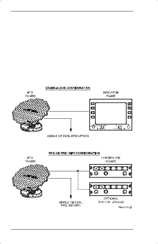
The PRIMUSR 660 Digital Weather Radar System can be operated in many configurations to display weather or ground mapping information on a radar indicator, electronic flight instrument system (EFIS) display, multifunction display (MFD), or on a combination of these displays. The various system configurations are summarized in the following paragraphs and shown in figure 2–1.
NOTE: Other configurations are possible but not illustrated.
The stand–alone configuration consists of two units: receiver transmitter antenna (RTA), and a dedicated radar indicator. In this configuration, the radar indicator contains all the controls to operate the PRIMUSR 660 Digital Weather Radar System. A single or dual Honeywell EFIS can be added to the stand–alone configuration. In such a case the electronic horizontal situation indicator (EHSI) repeats the data displayed on the radar indicator. System control remains with the radar indicator.
The second system configuration uses an RTA, and single or dual controllers. The single or dual EFIS is the radar display. Since there is no radar indicator in this configuration, the radar system operating controls are located on the controller. With a single controller, all cockpit radar displays are identical.
The dual configuration gives the appearance of having two radar systems on the aircraft. In the dual configuration, the pilot and copilot each select independent radar mode, range, tilt, and gain settings for display on their respective display. The dual configuration time shares the RTA. On the right–to–left antenna scan, the system switches to the mode, range, tilt, and gain selected by the left controller and updates the left display. On the reverse antenna scan, the system switches to the mode, range, tilt, and gain setting selected by the right controller and updates the right display. Either controller can be slaved to the other controller to show identical images on both sides of the cockpit.
A28–1146–111 |
System Configurations |
REV 2 |
2-1 |
PRIMUSR 660 Digital Weather Radar System
NOTES: 1. When WAIT, SECTOR SCAN, or FORCED STANDBY are activated, the radar operates as if in single controller configuration. This is an exception to the ability of each pilot to independently select modes.
2.In the dual configuration, the pilots can use the slave feature to optimize the update rate of each side’s weather radar display to meet the needs of the situation. With one controller turned off, both cockpit displays are updated on every sweep of the radar, but control of the radar is only on one side. With each controller operating, each side has control but each side is updated with new radar information on every other sweep of the antenna.
|
|
|
OFF |
OFF |
|
|
|
|
|
RCT |
STAB |
TGT |
SECT |
|
PULL |
WX |
GMAP |
|
PULL |
+ |
|
VAR |
STBY |
FP |
|
ACT |
15 |
|
|
OFF |
TEST |
0 |
||
MIN |
MAX |
RADAR |
SLV |
TILT |
– |
|
|
GAIN |
|
||||
|
|
|
OFF |
OFF |
|
|
|
|
|
RCT |
STAB |
TGT |
SECT |
|
PULL |
WX |
GMAP |
|
PULL |
+ |
|
VAR |
STBY |
FP |
|
ACT |
15 |
|
|
OFF |
TEST |
0 |
||
MIN |
MAX |
RADAR |
SLV |
TILT |
– |
|
|
GAIN |
|
||||
PRIMUSR 660 Configurations
Figure 2–1
System Configurations |
A28–1146–111 |
2-2 |
REV 2 |
PRIMUSR 660 Digital Weather Radar System
The third system configuration is similar to the second except that a Honeywell multifunction display (MFD) system is added. As before, single or dual controllers can be used. When a single controller is used, all displays show the same radar data. Dual controllers are used to operate in the dual mode. The MFD can be slaved to either controller to duplicate the data displayed on the selected side. Table 2–1 is a truth table for dual control modes.
Left |
Right |
|
|
|
Controller |
Controller |
Left Side |
Right Side |
RTA |
Mode |
Mode |
(NOTE 1) |
(NOTE 1) |
Mode |
|
|
|
|
|
|
|
|
|
|
OFF |
OFF |
OFF |
OFF |
OFF |
|
|
|
|
|
OFF |
Standby |
”SLV” |
Standby |
Standby |
|
|
Standby |
|
|
|
|
|
|
|
Standby |
OFF |
Standby |
”SLV” |
Standby |
|
|
|
Standby |
|
|
|
|
|
|
OFF |
ON |
”SLV” ON |
ON |
ON |
|
|
|
|
|
ON |
OFF |
ON |
”SLV” ON |
ON |
|
|
|
|
|
Standby |
ON |
Standby/ |
ON/2 |
ON |
|
|
2 |
|
|
|
|
|
|
|
ON |
Standby |
ON/2 |
Standby/2 |
ON |
|
|
|
|
|
ON |
ON |
ON/2 |
ON/2 |
ON |
|
|
|
|
|
Standby |
Standby |
Standby |
Standby |
Standby |
|
|
|
|
|
Dual Control Mode Truth Table
Table 2–1
NOTES: 1. ON is used to indicate any selected radar mode.
2.“SLV” means that displayed data is controlled by opposite side controller. That is, the one controller that is operating is controlling both sweeps of the antenna.
3.XXX/2 means that display is controlled by appropriate on–side control for the antenna sweep direction associated with that control. (/2 implies two controllers are ON.)
4.In standby, the RTA is centered in azimuth with 15_ upward tilt. Video data is suppressed. The transmitter is inhibited.
5.The MFD, if used, can repeat either left– or right–side data, depending upon external switch selection.
A28–1146–111 |
System Configurations |
REV 2 |
2-3 |

PRIMUSR 660 Digital Weather Radar System
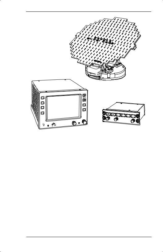
Equipment covered in this manual is listed in table 2–2 and shown in figure 2–2.
Model |
|
Unit |
Part No. |
|
|
|
|
|
|
||
Cockpit Mounted Options |
|
||
|
|
||
WI–650/660 |
Weather Radar Indicator |
7007700–VAR |
|
|
|
|
|
WC–660 |
|
Weather Radar Controller |
7008471–VAR |
|
|
|
|
Remote Mounted Equipment |
|
||
|
|
|
|
WU–660 |
|
Receiver Transmitter Antenna |
7021450–601 |
|
|
|
|
NOTES: 1. |
Typically, either the indicator or one of the remote controllers (one or |
||
|
two) is installed. |
|
|
2. Typical installed antenna sizes range from 12 to 18 inches in diameter.
PRIMUSR 660 Weather Radar Equipment List
Table 2–2
NOTE: A WC–650 Weather Radar Controller can be installed. Except as noted, its operation is identical to the WC–660 Weather Radar Controller.
System Configurations |
A28–1146–111 |
2-4 |
REV 2 |
PRIMUSR 660 Digital Weather Radar System
WU–660 RECEIVER/
TRANSMITTER/ANTENNA
 WC–660 WEATHER RADAR WI–650/660 WEATHER RADAR CONTROLLER
INDICATOR
AD–51768@
Typical PRIMUSR 660 Weather Radar Components
Figure 2–2
A28–1146–111 |
System Configurations |
REV 2 |
2-5/(2-6 blank) |
PRIMUSR 660 Digital Weather Radar System
3.Operating Controls
There are two basic controllers that are described in this section. They are (in order of description):
DWI–650/660 Weather Radar Indicator
DWC–660 Weather Radar Controller.
WI–650/660 WEATHER RADAR INDICATOR OPERATION
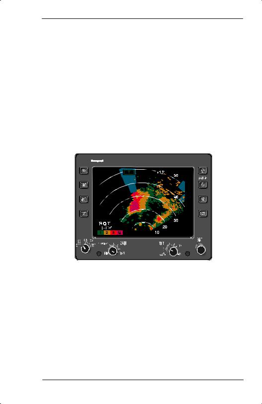
All controls used to operate the system display shown in figure 3–1, are located on the WI–650/660 Weather Radar Indicator front panel.
AUTO |
+1.0 |
TILT |
|
|
50 |

 40
40
30
20
1 2 3 4 |
T |
10 |
|
|
|
AD–51769–R1@
Typical PRIMUSR 660 Digital
Weather Radar Display
Figure 3–1
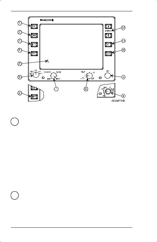
The controls and display features of the WI–650/660 Weather Radar Indicator are indexed and identified in figure 3–2. Brightness levels for all legends and controls on the indicator are controlled by the dimming bus for the aircraft panel.
A28–1146–111 |
Operating Controls |
REV 2 |
3-1 |
PRIMUSR 660 Digital Weather Radar System
WI–650/660 Weather Radar Indicator Front Panel View
Figure 3–2
1 WX (WEATHER)
The WX button is used to select the weather mode of operation. When WX is pushed, the system is fully operational and all internal parameters are set for enroute weather detection.
Alphanumerics are white, and WX is displayed in the mode field.
If WX is selected prior to the expiration of the initial RTA warm up period, the white WAIT legend is displayed in the mode field. In wait mode, the transmitter and antenna scan is inhibited and the memory is erased. Upon completion of the warmup period, the system automatically switches to WX mode.
WX can only be selected when the function switch is in the ON position.
2 GMP (GROUND MAPPING) OR MAP
GMP button selects the ground mapping mode. The system is fully operational and all parameters are set to enhance returns from ground targets.
NOTE: REACT or TGT modes are not selectable in GMP.
Operating Controls |
A28–1146–111 |
3-2 |
REV 2 |

PRIMUSR 660 Digital Weather Radar System
WARNING
WEATHER TYPE TARGETS ARE NOT CALIBRATED WHEN THE RADAR IS IN THE GMAP MODE. BECAUSE OF THIS, DO NOT USE THE GMAP MODE FOR WEATHER DETECTION.
As a constant reminder the GMP is selected, the alphanumerics are changed to green, the GMP legend is shown in the mode field, and the color scheme is changed to cyan, yellow, and magenta. Cyan represents the least reflective return, yellow is a moderated return, and magenta is a strong return.
If GMP is selected before the initial RTA warmup period is complete, the white WAIT legend is shown in the mode field. In wait mode, the transmitter and antenna scan are inhibited and the memory is erased. When the warmup period is complete, the system automatically switches to the GMP mode.
GMP can only be selected when the function switch is in the ON position.
3RCT (RAIN ECHO ATTENUATION COMPENSATION TECHNIQUE (REACT))
The RCT switch is an alternate–action switch that enables and disables REACT.
The REACT circuitry compensates for attenuation of the radar signal as it passes through rainfall. The cyan field indicates areas where further compensation is not possible. Any target detected within the cyan field cannot be calibrated and should be considered dangerous. All targets in the cyan field are displayed as fourth level precipitation, magenta.
REACT is available in the WX mode only, and selecting REACT forces the system to preset gain. When engaged, the white RCT legend is displayed in the REACT field.
NOTES: 1. REACT’S three main functions (attenuation compensation, cyan field, and forcing targets to magenta) are switched on and off with the RCT switch.
2.Refer to Section 5, Radar Facts, for a description of REACT.
A28–1146–111 |
Operating Controls |
REV 2 |
3-3 |

PRIMUSR 660 Digital Weather Radar System
4 TGT (TARGET)
The TGT button is an alternate–action switch that enables and disables the radar target alert feature. Target alert is selectable in all but the 300–mile range. When selected, target alert monitors beyond the selected range and 7.5° on each side of the aircraft heading. If a return with target alert characteristics is detected in the monitored area, the target alert legend changes from the green T armed condition to the yellow TGT warning condition. (See the target alert characteristics in table 3–1 for a target description.) These annunciations advise the pilot of potentially hazardous targets directly in front of the aircraft that are outside the selected range. When a yellow warning is received, the pilot should select longer ranges to view the questionable target. (Note that target alert is inactive within the selected range.)
Selecting target alert forces the system to preset gain. Target alert can be selected only in the WX or FP (flight plan) modes.
NOTE: In order to activate the target alert warning, the target must have the depth and range characteristics described in table 3–1.
Selected Range |
Minimum Target |
Target Range |
(NM) |
Depth (NM) |
(NM) |
|
|
|
|
|
|
5 |
5 |
5–55 |
10 |
5 |
10–60 |
25 |
5 |
25–75 |
50 |
5 |
50–100 |
100 |
5 |
100–150 |
200 |
5 |
200–250 |
300 |
N/A |
N/A |
FP (Flight Plan) |
5 |
5–55 |
|
|
|
Target Alert Characteristics
Table 3–1
Operating Controls |
A28–1146–111 |
3-4 |
REV 2 |
PRIMUSR 660 Digital Weather Radar System
5 DISPLAY AREA
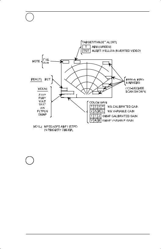
See figure 3–3 and the associated text that explains the alphanumeric display.
AD–51771@
WI–650/660 Weather Radar Indicator Display Screen Features
Figure 3–3
6 FUNCTION SWITCH
A rotary switch is used to select the following functions:
DOFF– This position turns off the radar system.
DSBY (Standby) – This position places the radar system in standby, a ready state, with the antenna scan stopped, the transmitter inhibited, and the display memory erased. STBY, in white, is shown in the mode field.
If SBY is selected before the initial RTA warmup period is complete (approximately 90 seconds), the white WAIT legend is shown in the mode field. When warmup is complete, the system changes the mode field to SBY.
A28–1146–111 |
Operating Controls |
REV 2 |
3-5 |

PRIMUSR 660 Digital Weather Radar System
DON – Places the system in the operational mode selected by the WX or MAP (GMP) button. When WX is selected, the system is fully operational and all internal parameters are set for enroute weather detection. The alphanumerics are white and WX is shown in the mode field.
If ON is selected before the initial RTA warmup period is over (approximately 90 seconds), the white WAIT legend is displayed in the mode field. In wait mode, the transmitter and antenna scan are inhibited and the display memory is erased. When the warmup is complete, the system automatically switches to the WX (or MAP) mode, as selected.
The system, in preset gain, with WX selected, is calibrated as listed in table 3–2.
Rainfall Rate |
Color |
||
|
|
||
in/hr |
mm/hr |
||
|
|||
|
|
|
|
|
|
|
|
.04–.16 |
1–4 |
Green |
|
|
|
|
|
.16–.47 |
4–12 |
Yellow |
|
|
|
|
|
.47–2 |
12–50 |
Red |
|
|
|
|
|
> 2 |
>5 0 |
Magenta |
|
|
|
|
|
Rainfall Rate Color Coding
Table 3–2
DFP (Flight Plan) – The FP position puts the radar system in the flight plan mode, that clears the screen of radar data so ancillary data can be displayed. Examples of this data are:
-Electronic checklists
-Navigation displays
-Electrical discharge (lightning) data.
NOTE: In the FP mode, the radar RTA is put in standby, the alphanumerics are changed to cyan, and the FLTPLN (flight plan) legend is shown in the mode field.
Operating Controls |
A28–1146–111 |
3-6 |
REV 2 |

PRIMUSR 660 Digital Weather Radar System
The TGT alert mode can be used in the FP mode. With target alert on and the FP mode selected, the target alert armed annunciation (green TGT) is displayed. The RTA searches for a hazardous target from 5 to 55 miles and ±7.5° of the aircraft heading. No radar targets are displayed. If a hazardous target is detected, the target alert armed annunciation switches to the alert annunciation (yellow TGT). This advises the pilot that a hazardous target is in his flightpath and the WX mode should be selected to view it.
NOTE: The TGT function is inoperative when a checklist is displayed.
DTST (Test) – The TST position selects the radar test mode. A special test pattern is displayed to verify system operation. The TEST legend is shown in the mode field. Refer to Section 4, Normal Operations, for a description of the test pattern.
WARNING
IN THE TEST MODE THE TRANSMITTER IS ON AND RADIATING X–BAND MICROWAVE ENERGY. REFER TO SECTION 6, MAXIMUM PERMISSIBLE EXPOSURE LEVEL (MPEL), AND THE APPENDIX, FEDERAL AVIATION ADMINISTRATION (FAA) ADVISORY CIRCULARS, TO PREVENT POSSIBLE HUMAN BODY DAMAGE.
FSBY (FORCED STANDBY)
FSBY is an automatic, nonselectable radar mode. As an installation option, the indicator can be wired to the weight–on–wheels (WOW) squat switch. When wired, the RTA is in the FSBY mode when the aircraft is on the ground. In FSBY mode, the transmitter and antenna scan are both inhibited, and the forced standby legend is displayed in the mode field.
The FSBY mode is a safety feature that inhibits the transmitter on the ground to eliminate the X–band microwave radiation hazard. Refer to Section 6, Maximum Permissible Exposure Level (MPEL).
When in FSBY mode, you can restore normal operation by pulling the tilt control out, pushing it in, pulling it out, and pushing it in within three seconds.
WARNING
STANDBY OR FORCED STANDBY MODE MUST BE VERIFIED FOR GROUND OPERATION BY THE OPERATOR TO ENSURE SAFETY FOR GROUND PERSONNEL.
A28–1146–111 |
Operating Controls |
REV 2 |
3-7 |
Loading...