


 Loading...
HoneywellConnectedLifeSafetyServices
GLSS Gateway
Installation and User’s Manual
LS10237-000NF-E | REV. A | 31/01/2020
Table of Contents |
|
Section1:GeneralInformation......................................................................................................................................... |
4 |
1.1:AboutThisManual....................................................................................................................................................................... |
4 |
1.2:InformationSources.................................................................................................................................................................... |
4 |
1.3:DocumentationFeedback........................................................................................................................................................ |
5 |
1.4:AbbreviationsUsedinThisDocument................................................................................................................................ |
5 |
1.5:FCCSTATEMENT........................................................................................................................................................................... |
6 |
1.6:WarningsandCautions.............................................................................................................................................................. |
6 |
1.7:Disclaimer......................................................................................................................................................................................... |
6 |
Section2:Overview.............................................................................................................................................................. |
7 |
2.1:Operations........................................................................................................................................................................................ |
7 |
2.2:HoneywellConnectedLifeSafetyServices....................................................................................................................... |
7 |
2.3:TheGatewayBoard’sLayout.................................................................................................................................................... |
7 |
2.3.1:ConnectingInterfaces.................................................................................................................................................... |
8 |
2.3.2:LEDIndicators.................................................................................................................................................................... |
9 |
2.3.3:SwitchesontheGatewayBoard.............................................................................................................................. |
11 |
Section3:Installation....................................................................................................................................................... |
12 |
1.1:WallMountingtheDedicatedGateway............................................................................................................................ |
12 |
3.2:GatewayBoardConnections................................................................................................................................................. |
14 |
3.2.1:ConnectingtoaFireAlarmPanel........................................................................................................................... |
15 |
SupportedPanels................................................................................................................................................................. |
15 |
VigilonPanels:ConnectionOptions............................................................................................................................ |
15 |
NotifierPanels:ConnectionOptions........................................................................................................................... |
15 |
ToMakeaUSBConnection............................................................................................................................................. |
16 |
ToMakeaNUP/RS232Connection.......................................................................................................................... |
16 |
Thepanelsuppliesthe24VDCpowertothegatewayboardthroughtheNUPconnection............ |
16 |
ToMakeaUART/TTLConnection................................................................................................................................ |
16 |
Section4:Configurations................................................................................................................................................ |
18 |
4.1:PanelConfigurations............................................................................................................................................................... |
18 |
4.1.1:TheDateSettings........................................................................................................................................................... |
18 |
4.2:GatewayConfigurations......................................................................................................................................................... |
18 |
4.2.1:ToConfigureviatheWirelessConnection.......................................................................................................... |
18 |
4.3:VerifyingtheGatewayConnections................................................................................................................................... |
20 |
4.4:TestingtheCommissioning................................................................................................................................................... |
20 |
2

|
TableofContents |
Section5:Post-InstallationActivities......................................................................................................................... |
22 |
5.1:MaintenanceTesting................................................................................................................................................................ |
22 |
5.2:UpgradingtheGatewayFirmware...................................................................................................................................... |
22 |
5.2.1:ToUpgradetoaLaterRelease................................................................................................................................. |
22 |
5.2.2:ToVerifytheUpgrade................................................................................................................................................... |
23 |
5.2.3:LEDIndicationsDuringtheUpgrade.................................................................................................................... |
23 |
5.3:Troubleshooting.......................................................................................................................................................................... |
24 |
5.3.1:ToTroubleshootLED-IndicatedIssues................................................................................................................ |
24 |
5.3.2:ToTroubleshootOtherIssues................................................................................................................................... |
25 |
AppendixA:GatewayOperatingConditions.............................................................................................................. |
26 |
AppendixB:ModulationsandPowerUsed................................................................................................................. |
27 |
3

Section1:GeneralInformation
1.1 About This Manual
This GLSS Gateway Installation and User’s Manual provides detailed procedures about installation, deployment, and upgrade of Honeywell Connected Life Safety Services. The manual describes:
•the dedicated CCM gateway,
•its installation environment,
•mounting and connecting the gateway circuit board to a fire detection panel, and
•initial network configurations
Using This Manual This manual is written with the understanding that the user is trained in the operations and services required for this product.
 NOTE:In this manual, the GLSS Gateway’s printed circuit board is also called as the
 gateway board.
1.2 Information Sources
The table below lists related documents:
Table 1.1: Supplemental Documents
Product Type: Honeywell Connected Life Safety Services Gateway For This Purpose ... Refer to ...
Get comprehensive GLSS Gateway Installation and User’s Manual (This document) installation and Part Number 50151849-001
configuration process details
Product Type: Notifier Panels
For This Purpose ... |
Refer to ... |
NCA Panel |
|
Install the NCA panel |
NCA Installation Manual |
|
51482 |
NCA-2 Panel |
|
Install the NCA-2 |
NCA-2 Installation Manual |
panel |
52482 |
NFS-320 Panel |
|
Install the NFS-320 |
NFS-320 Installation Manual |
panel |
52745 |
Customize the NFS- |
NFS-320 Programming Manual |
320 panel |
52746 |
Operate the NFS-320 |
NFS-320 Operations Manual |
panel |
52747 |
NFS2-640 Panel |
|
Install the NFS2-640 |
NFS2-640 Installation Manual |
panel |
52741 |
Customize the NFS2- |
NFS2-640 Programming Manual |
640 panel |
52742 |
Operate the NFS2-640 |
NFS2-640 Operations Manual |
panel |
52743 |
NFS-3030 Panel |
|
Install the NFS-3030 |
NFS-3030 Installation Manual |
panel |
51330 |
Customize the NFS- |
NFS-3030 Programming Manual |
3030 panel |
51344 |
4
P/N: LS10237-000NF-E | Rev A.

Documentation Feedback
Product Type: Honeywell Connected Life Safety Services Gateway
Operate the NFS-3030 |
NFS-3030 Operational Manual |
panel |
51345 |
NFS2-3030 Panel |
|
Install the NFS2-3030 |
NFS2-3030 Installation Manual |
panel |
52544 |
Customize the NFS2- |
NFS2-3030 Programming Manual |
3030 panel |
52545 |
Operate the NFS2- |
NFS2-3030 Operations Manual |
3030 panel |
52546 |
1.3 Documentation Feedback
Your feedback helps us keep our documentation up-to-date and accurate. If you have any comments or suggestions about our Online Help or printed documents, you can email us.
Please include the following information:
•Product name and version number (if applicable)
•Printed document or Online Help
•Topic title (for Online Help)
•Page number (for printed document)
•A brief description of content you think should be improved or corrected
•Your suggestion for how to correct/improve documentation
Send email messages to: FireSystem.TechPubs@Honeywell.com
Please note this email address is for documentation feedback only. If you have any technical issues, please contact Honeywell Technical Services.
1.4 Abbreviations Used in This Document
|
Table 1.2: Abbreviations List |
Abbreviation |
Description |
DACT |
Digital Alarm Communicator Transmitter |
ESD |
Engineered Systems Distributor |
NFN |
Noti-FIRE-Net Network |
NUP |
Notifier Universal Protocol |
|
The Universal Protocol by Notifier for all fire alarm panel communications. This |
|
protocol enables direct transfer of data between the panels and networks, |
|
without the need to translate. |
OC |
Ownership Code |
|
The code that confirms ownership of the gateway |
TTL |
Transistor-Transistor Logic |
|
A physical connection for performing both the logic gating and amplifying |
|
functions on the serial data. |
UART |
Universal Asynchronous Receiver/Transmitter |
|
A physical connection that converts and provides serial data for the panel and |
|
parallel data for the gateway. |
USB |
Universal Serial Bus |
5
P/N: LS10237-000NF-E | Rev A.
FCCSTATEMENT
1.5 FCC STATEMENT
This device complies with Part 15 of the FCC Rules. Operation is subject to the following two conditions: (1) This device may not cause harmful interference. (2) This device must accept any interference received, including, an interference that may cause undesired operation.
FCC ID: PV3CGWMB
1.6 Warnings and Cautions
CAUTION:USERS MUST FOLLOW THE PROCESSES AND USAGES APPROVED AS PER COMPLIANCE. A CHANGED OR MODIFIED USAGE NOT EXPRESSLY APPROVED BY COMPLIANCE COULD VOID THE USER'S AUTHORITY TO OPERATE THE GLSS GATEWAY.
WARNING:
THESEINSTRUCTIONSCONTAINPROCEDURESTOFOLLOWTOAVOIDINJURYAND DAMAGETOEQUIPMENT. IT IS ASSUMED THAT THE USER OF THIS MANUAL HAS BEEN SUITABLY TRAINED AND IS FAMILIAR WITH THE RELEVANT REGULATIONS.
ELECTRO-STATIC SENSITIVE DEVICES:
TAKE SUITABLE ESD PRECAUTIONS WHEN REMOVING OR INSTALLING PRINTED CIRCUIT BOARDS.
THIS GATEWAY’S PANEL IS CE MARKED TO SHOW THAT IT CONFORMS TO THE REQUIREMENTS OF THE FOLLOWING EUROPEAN COMMUNITY DIRECTIVES:
• EMC Directive |
2014/30/EU |
• Low Voltage Directive (LVD) |
2014/35/EU |
• Radio Equipment Directive |
2014/53/EU |
• RoHS Directive |
2011/65/EU |
• WEEE Directive |
2012/19/EU |
The gateway is designed to meet Additional National Requirements: EFSG [BRE, AFNOR/CNPP, and VdS], Incert, SBSC, EMEA, and EAC
1.7 Disclaimer
Images in the document are for reference purpose only and are subject to change. All trademarks, service marks, word marks, design marks, and logos are property of their respective owners.
6

Section2:Overview
GLSS Gateway is an embedded and intelligent gateway for connected buildings. It enables system maintenance providers as well as end users to remotely manage connected fire detection systems. The gateway also supports them to ensure compliance.
 CAUTION: THE GATEWAY MUST BE INSTALLED INDOORS.
2.1 Operations
The gateway acts as a portal among fire alarm panels, Cloud, and peripheral devices. The gateway connection with the fire alarm panel enables reading the inventory and transmitting the data. The connection with Cloud facilitates remotely monitoring and managing the fire detection systems.
2.2 Honeywell Connected Life Safety Services
The software suite enables remote management of fire detection systems. It monitors the building’s fire system events in real-time and notifies users about the events immediately. It also supports periodical maintenance activities and helps in reports generation.
2.3 The Gateway Board’s Layout
The illustration below points out those parts that are used for connections and trouble shooting.
Tamper Switch 2 (On the back side)
Figure 2.1: Printed Circuit Board: Layout
7

The Gateway Board’s Layout
2.3.1 Connecting Interfaces
Figure 2.1 uses numbered labels to show the location of the interfaces for connections. This manual uses these numbered labels at various places for your convenience.
The table below uses these numbered labels to describe the type and usage of the interfaces.
|
|
Table 2.1: Gateway Interface Details |
Label |
Interface Type |
Usage |
No. |
|
|
1Ethernet 1 Primary Ethernet port that can permanently connect the gateway board with
the CLSS Cloud services.
Cable: CAT 5 standard Ethernet cable with RJ45 connector
2Ethernet 2 Secondary Ethernet port providing a TCP/IP connection to one of the
compatible Notifier panel.
Cable: CAT 5 standard Ethernet cable with RJ45 connector
3 |
RS485B |
For future use |
4 |
RS485A |
For future use |
5 |
UART/TTL |
Connects the gateway board to a UART/TTL-compatible fire alarm panel. |
|
|
This connection enables the fire alarm panel to send the alarm data and |
|
|
device data to the gateway. |
6NUP (RS232) Transfer of fire-related and device-related data from the panel to Cloud
through the gateway. It also helps in administering the fire detection system. Connects the gateway board to one of the following:
•An NFN network control module (NCM, NCM-2, or HS-NCM)
•A Notifier panel
If the connected panel supplies power, the gateway would get power from the panel through the NUP port.
7 |
Power |
Connects to an external 24-volt DC power when required. It uses a power- |
|
|
limited, regulated, power-supply-listed connection for fire-protective |
|
|
signaling. |
|
|
It is used only when the gateway board is connected with: |
|
|
• A network card, or |
|
|
• A Notifier panel through USB |
8 |
USB |
Transfer of fire-related and device-related data from the panel to Cloud |
|
|
through the gateway. It also helps in administering the fire detection system. |
|
|
Connects to a Notifier panel |
9 |
Wireless |
Enables the gateway to have a wireless or mobile Low Energy Antennas for |
|
Antennas |
communication with Cloud |
10 |
Cellular |
Enables the gateway to report alarms and supervision messages to a central |
|
|
receiving station. It is a 40-pin expansion slot for an LTE communicator. |
8
The Gateway Board’s Layout
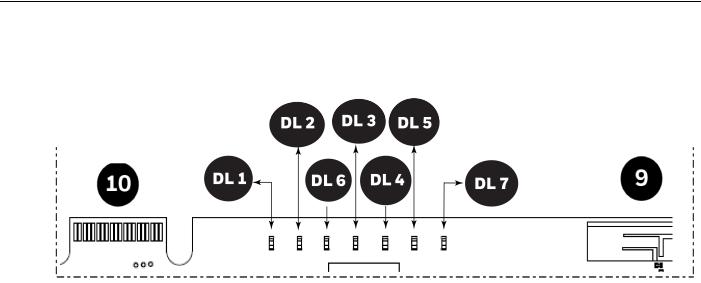
2.3.2 LED Indicators
The LED indicators on the GLSS Gatewayboard use differentcolors toidentifyvariousoperational status of the gateway. To know the location of the LED indicators on the gateway board, refer Figure 2.1: “Printed Circuit Board: Layout” on page 7.
Figure 2.2: The LED Indicators on the Gateway
9
Loading...