


 Loading...
YASKAWA AC Drive-J1000
Compact V/f Control Drive
Quick Start Guide
Type: CIMR-JU
Models: 200 V Class, Three-Phase Input: 0.1 to 5.5 kW 200 V Class, Single-Phase Input: 0.1 to 2.2 kW 400 V Class, Three-Phase Input: 0.2 to 5.5 kW
To properly use the product, read this manual thoroughly and retain for easy reference, inspection, and maintenance. Ensure the end user receives this manual.
Receiving
Mechanical Installation
Electrical Installation
Start-Up Programming &
Operation
Troubleshooting
Periodic Inspection &
Maintenance
Peripheral Devices &
Options
Specifications
Parameter List
Standards Compliance
1
2
3
4
5
6
7
A
B
C
MANUAL NO. TOEP C710606 26D
Copyright © 2008 YASKAWA ELECTRIC CORPORATION. All rights reserved.
All rights reserved. No part of this publication may be reproduced, stored in a retrieval system, or transmitted, in any form or by any means, mechanical, electronic, photocopying, recording, or otherwise, without the prior written permission of Yaskawa. No patent liability is assumed with respect to the use of the information contained herein. Moreover, because Yaskawa is constantly striving to improve its high-quality products, the information contained in this manual is subject to change without notice. Every precaution has been taken in the preparation of this manual. Yaskawa assumes no responsibility for errors or omissions. Neither is any liability assumed for damages resulting from the use of the information contained in this publication.

Table of Contents
i. PREFACE & GENERAL SAFETY |
........................9 |
|
i.1 |
Preface .................................................................. |
10 |
|
Applicable Documentation .......................................... |
10 |
|
Symbols.................................................................. |
10 |
|
Terms and Abbreviations............................................ |
10 |
i.2 |
General Safety ....................................................... |
11 |
|
Supplemental Safety Information.................................. |
11 |
|
Safety Messages ...................................................... |
12 |
|
Drive Label Warnings ................................................ |
15 |
|
Warranty Information ................................................. |
16 |
|
Quick Reference....................................................... |
16 |
1. |
RECEIVING ......................................................... |
17 |
|
|
1.1 |
Section Safety........................................................ |
18 |
|
1.2 |
Model Number and Nameplate Check.................... |
19 |
|
|
Nameplate............................................................... |
19 |
|
1.3 |
Component Names ................................................ |
22 |
|
|
IP20/Open-Chassis ................................................... |
22 |
|
|
Front Views ............................................................. |
24 |
2. |
MECHANICAL INSTALLATION ......................... |
25 |
|
YASKAWA ELECTRIC TOEP C710606 26D YASKAWA AC Drive – J1000 Quick Start Guide |
3 |

Table of Contents
2.1 |
Section Safety.................................................................. |
26 |
2.2 |
Mechanical Installation .................................................... |
29 |
|
Installation Environment ....................................................... |
29 |
|
Installation Orientation and Spacing........................................ |
30 |
|
Exterior and Mounting Dimensions ......................................... |
32 |
3. ELECTRICAL INSTALLATION.................................... |
35 |
|
3.1 |
Section Safety.................................................................. |
36 |
3.2 |
Standard Connection Diagram......................................... |
39 |
3.3 |
Main Circuit Connection Diagram .................................... |
42 |
|
Single-Phase 200 V Class Models BA0001 to BA0010 ............... |
42 |
|
Three-Phase 200 V Class Models 2A0001 to 2A0020 |
|
|
Three-Phase 400 V Class Models 4A0001 to 4A0011 ............... |
42 |
3.4 |
Terminal Block Configuration.......................................... |
43 |
3.5 |
Protective Covers ............................................................ |
44 |
|
IP20/Open-Chassis Cover Removal and Installation................... |
44 |
3.6 |
Main Circuit Wiring .......................................................... |
46 |
|
Main Circuit Terminal Functions ............................................. |
46 |
|
Wire Gauges and Tightening Torques ..................................... |
46 |
|
Main Circuit Terminal Power Supply and Motor Wiring................ |
49 |
3.7 |
Control Circuit Wiring ...................................................... |
52 |
|
Control Circuit Terminal Block Functions.................................. |
53 |
|
Terminal Configuration......................................................... |
54 |
|
Wiring Procedure ................................................................ |
56 |
3.8 |
I/O Connections ............................................................... |
59 |
|
Sinking/Sourcing Mode Switch............................................... |
59 |
3.9 |
Main Frequency Reference .............................................. |
62 |
|
DIP Switch S1 Analog Input Signal Selection ............................ |
62 |
3.10 Braking Resistor.............................................................. |
64 |
|
|
Installation......................................................................... |
64 |
3.11 Interlocking with Connected Machinery .......................... |
66 |
|
|
Drive Ready Signal ............................................................. |
66 |
3.12 Wiring Checklist .............................................................. |
67 |
|
4 |
YASKAWA ELECTRIC TOEP C710606 26D YASKAWA AC Drive – J1000 Quick Start Guide |

|
Table of Contents |
|
4. START-UP PROGRAMMING & OPERATION............. |
69 |
|
4.1 |
Section Safety.................................................................. |
70 |
4.2 Using the Digital LED Operator........................................ |
73 |
|
|
Keys, Displays, and LEDs..................................................... |
73 |
|
Digital Text Display ............................................................. |
75 |
|
LED Screen Displays........................................................... |
76 |
|
LO/RE LED and RUN LED Indications .................................... |
76 |
|
Menu Structure for Digital LED Operator.................................. |
78 |
4.3 The Drive and Programming Modes ................................ |
79 |
|
|
Navigating the Drive and Programming Modes.......................... |
80 |
|
Changing Parameter Settings or Values .................................. |
83 |
|
Verifying Parameter Changes: Verify Menu .............................. |
84 |
|
Switching Between LOCAL and REMOTE................................ |
85 |
|
Parameters Available in the Setup Group................................. |
86 |
4.4 |
Start-up Flowchart ........................................................... |
87 |
|
Flowchart: Basic Start-up...................................................... |
87 |
4.5 |
Basic Operation ............................................................... |
88 |
|
Initialize Parameter Values: A1-03.......................................... |
88 |
|
Frequency Reference Source: b1-01....................................... |
88 |
|
Run Command Input Selection: b1-02 ..................................... |
90 |
|
Stopping Method Selection: b1-03 .......................................... |
92 |
|
Acceleration/Deceleration: C1-01 to C1-04............................... |
93 |
|
Drive Duty and Carrier Frequency Selection: C6-01 and C6-02 .... |
95 |
|
Multi-Step Speed Operation (4-Step Speed) ............................. |
97 |
|
E1: V/f Characteristics ....................................................... |
101 |
|
Motor Parameters: E2-01 to E2-03 ....................................... |
104 |
|
Digital Output: H2-01 ......................................................... |
105 |
|
Analog Outputs: H4-01 to H4-03 .......................................... |
105 |
|
Motor Protection: L1-01 and L1-02 ....................................... |
107 |
|
Drive Status Monitors: U1-01 to U4-13 .................................. |
110 |
4.6 Powering Up the Drive .................................................... |
112 |
|
|
Powering Up the Drive and Operation Status Display ............... |
112 |
|
V/f Pattern Setting............................................................. |
113 |
4.7 No-Load Operation Test Run .......................................... |
114 |
|
|
No-Load Operation Test Run............................................... |
114 |
YASKAWA ELECTRIC TOEP C710606 26D YASKAWA AC Drive – J1000 Quick Start Guide |
5 |

Table of Contents
4.8 |
Test Run with Load Connected....................................... |
116 |
|
Test Run with the Load Connected ....................................... |
116 |
4.9 |
Verifying and Backing Up Parameter Settings................ |
117 |
|
Parameter Access Level: A1-01 ........................................... |
117 |
|
Password Settings: A1-04, A1-05 ......................................... |
117 |
|
Copy Function (Optional).................................................... |
117 |
4.10 Test Run Checklist ......................................................... |
119 |
|
5. TROUBLESHOOTING ............................................... |
121 |
|
5.1 |
Section Safety................................................................. |
122 |
5.2 |
Motor Performance Fine Tuning ..................................... |
125 |
|
Parameters for Tuning the Drive .......................................... |
125 |
|
Motor Hunting and Oscillation Control Parameters ................... |
126 |
5.3 |
Drive Alarms, Faults, and Errors..................................... |
127 |
|
Types of Alarms, Faults, and Errors ...................................... |
127 |
|
Alarm and Error Displays.................................................... |
128 |
5.4 |
Fault Detection ............................................................... |
130 |
|
Fault Displays, Causes, and Possible Solutions ...................... |
130 |
5.5 |
Alarm Detection .............................................................. |
141 |
|
Alarm Codes, Causes, and Possible Solutions ........................ |
141 |
5.6 |
Operator Programming Errors ........................................ |
147 |
|
oPE Codes, Causes, and Possible Solutions .......................... |
147 |
5.7 |
Diagnosing and Resetting Faults.................................... |
149 |
|
Fault Occurs Simultaneously with Power Loss ........................ |
149 |
|
If the Drive Still has Power After a Fault Occurs ...................... |
149 |
|
Viewing Fault History Data After Fault ................................... |
149 |
|
Fault Reset Methods ......................................................... |
150 |
5.8 |
Troubleshooting without Fault Display........................... |
151 |
|
Cannot Change Parameter Settings...................................... |
151 |
|
Motor Does Not Rotate Properly after Pressing RUN Button or |
|
|
after Entering External Run Command ................................. |
152 |
6. PERIODIC INSPECTION & MAINTENANCE ........... |
161 |
|
6.1 |
Section Safety................................................................. |
162 |
6 |
YASKAWA ELECTRIC TOEP C710606 26D YASKAWA AC Drive – J1000 Quick Start Guide |

|
Table of Contents |
|
6.2 |
Inspection....................................................................... |
165 |
|
Recommended Daily Inspection........................................... |
165 |
|
Recommended Periodic Inspection....................................... |
166 |
6.3 |
Periodic Maintenance ..................................................... |
168 |
|
Replacement Parts............................................................ |
168 |
6.4 |
Drive Cooling Fans ......................................................... |
171 |
|
Number of Cooling Fans..................................................... |
171 |
|
Cooling Fan Replacement .................................................. |
172 |
7. PERIPHERAL DEVICES & OPTIONS ...................... |
177 |
|
7.1 |
Section Safety................................................................. |
178 |
7.2 |
Drive Options and Peripheral Devices ............................ |
180 |
7.3 |
Connecting Peripheral Devices ...................................... |
182 |
7.4 |
Installing Peripheral Devices .......................................... |
184 |
|
Installing a Molded Case Circuit Breaker (MCCB) and Earth |
|
|
Leakage Circuit Breaker (ELCB) ......................................... |
184 |
|
Application Precautions when Installing a GFCI....................... |
185 |
|
Installing a Magnetic Contactor ............................................ |
185 |
|
Connecting an AC Reactor or DC Link Choke ......................... |
186 |
|
Connecting a Surge Suppressor .......................................... |
187 |
|
Connecting a Noise Filter ................................................... |
187 |
|
EMC Filter Installation........................................................ |
190 |
|
Zero-Phase Reactor .......................................................... |
190 |
|
Installing Fuses on the Input Side......................................... |
191 |
|
Attachment for External Heatsink ......................................... |
191 |
|
Noise Filter Installation....................................................... |
191 |
|
Installing a Motor Thermal Overload (oL) Relay on the Drive |
|
|
Output........................................................................... |
191 |
|
NEMA Type 1 Kit .............................................................. |
193 |
7.5 |
Options ........................................................................... |
198 |
|
Interface Options .............................................................. |
198 |
|
Other Options .................................................................. |
198 |
A. SPECIFICATIONS...................................................... |
199 |
|
A.1 Heavy Duty and Normal Duty Ratings............................. |
200 |
|
YASKAWA ELECTRIC TOEP C710606 26D YASKAWA AC Drive – J1000 Quick Start Guide |
7 |

Table of Contents
A.2 |
Single/Three-Phase 200 V Class Drives .......................... |
201 |
A.3 |
Three-Phase 400 V Class Drives ..................................... |
203 |
A.4 |
Drive Specifications........................................................ |
205 |
A.5 |
Drive Watt Loss Data ...................................................... |
209 |
A.6 |
Drive Derating Data......................................................... |
211 |
|
Temperature Derating........................................................ |
211 |
|
Altitude Derating ............................................................... |
212 |
B. PARAMETER LIST .................................................... |
213 |
|
B.1 |
Parameter Groups .......................................................... |
214 |
B.2 |
Parameter Table.............................................................. |
215 |
|
A: Initialization Parameters ................................................. |
215 |
|
b: Application ................................................................... |
216 |
|
C: Tuning ........................................................................ |
217 |
|
d: References .................................................................. |
220 |
|
E: Motor Parameters ......................................................... |
222 |
|
H Parameters: Multi-Function Terminals ................................ |
223 |
|
L: Protection Function ........................................................ |
229 |
|
n: Advanced Performance Set-Up ........................................ |
233 |
|
o: Operator Related Parameters .......................................... |
233 |
|
U: Monitors...................................................................... |
235 |
B.3 |
Defaults by Drive Model and Duty Rating ND/HD............ |
238 |
C. STANDARDS COMPLIANCE .................................... |
241 |
|
C.1 |
Section Safety................................................................. |
242 |
C.2 |
European Standards ....................................................... |
245 |
|
CE Low Voltage Directive Compliance .................................. |
245 |
|
EMC Guidelines Compliance............................................... |
248 |
C.3 |
UL Standards.................................................................. |
254 |
|
UL Standards Compliance .................................................. |
254 |
|
Drive Motor Overload Protection .......................................... |
260 |
INDEX ......................................................................... |
263 |
|
8 |
YASKAWA ELECTRIC TOEP C710606 26D YASKAWA AC Drive – J1000 Quick Start Guide |

i
Preface & General
Safety
This section provides safety messages pertinent to this product that, if not heeded, may result in fatality, personal injury, or equipment damage. Yaskawa is not responsible for the consequences of ignoring these instructions.
i.1 |
PREFACE......................................................... |
10 |
i.2 |
GENERAL SAFETY........................................... |
11 |
YASKAWA ELECTRIC TOEP C710606 26D YASKAWA AC Drive – J1000 Quick Start Guide |
9 |
i.1 Preface
i.1 Preface
Yaskawa manufactures products used as components in a wide variety of industrial systems and equipment. The selection and application of Yaskawa products remain the responsibility of the equipment manufacturer or end user. Yaskawa accepts no responsibility for the way its products are incorporated into the final system design. Under no circumstances should any Yaskawa product be incorporated into any product or design as the exclusive or sole safety control. Without exception, all controls should be designed to detect faults dynamically and fail safely under all circumstances. All systems or equipment designed to incorporate a product manufactured by Yaskawa must be supplied to the end user with appropriate warnings and instructions as to the safe use and operation of that part. Any warnings provided by Yaskawa must be promptly provided to the end user. Yaskawa offers an express warranty only as to the quality of its products in conforming to standards and specifications published in the Yaskawa manual. NO OTHER WARRANTY, EXPRESS OR IMPLIED, IS OFFERED. Yaskawa assumes no liability for any personal injury, property damage, losses, or claims arising from misapplication of its products.
u Applicable Documentation
The following manuals are available for J1000 series drives:
J1000 Series Compact V/f Control Drive Quick Start Guide
Read this manual first. This guide is packaged together with the product. It contains basic information required to install and wire the drive. This guide provides basic programming and simple setup and adjustment. Refer to the J1000 Technical Manual for complete descriptions of drive features and functions.
J1000 Series Compact V/f Control Drive Technical Manual
This manual describes installation, wiring, operation procedures, functions, troubleshooting, maintenance, and inspections to perform before operation.
u Symbols
Note: Indicates a supplement or precaution that does not cause drive damage.
Indicates a term or definition used in this manual.
TERMS
u Terms and Abbreviations
•Drive: Yaskawa J1000 Series Drive
•r/min: Revolutions per Minute
•SI-485/J: RS-422/RS-485 Interface for MEMOBUS/Modbus Communication
•V/f: V/f Control
10 |
YASKAWA ELECTRIC TOEP C710606 26D YASKAWA AC Drive – J1000 Quick Start Guide |
i.2 General Safety
i.2 General Safety
u Supplemental Safety Information
General Precautions
•The diagrams in this manual may be indicated without covers or safety shields to show details. Restore covers or shields before operating the drive and run the drive according to the instructions described in this manual.
•Any illustrations, photographs, or examples used in this manual are provided as examples only and may not apply to all products to which this manual is applicable.
•The products and specifications described in this manual or the content and presentation of the manual may be changed without notice to improve the product and/or the manual.
•When ordering a new copy of the manual due to damage or loss, contact your Yaskawa representative or the nearest Yaskawa sales office and provide the manual number shown on the front cover.
•If nameplate becomes worn or damaged, order a replacement from your Yaskawa representative or the nearest Yaskawa sales office.
 WARNING
Read and understand this manual before installing, operating or servicing this drive. The drive must be installed according to this manual and local codes.
The following conventions are used to indicate safety messages in this manual. Failure to heed these messages could result in serious or possibly even fatal injury or damage to the products or to related equipment and systems.
 DANGER
Indicates a hazardous situation, which, if not avoided, will result in death or serious injury.
 WARNING
Indicates a hazardous situation, which, if not avoided, could result in death or serious injury.
WARNING! will also be indicated by a bold key word embedded in the text followed by an italicized safety message.
YASKAWA ELECTRIC TOEP C710606 26D YASKAWA AC Drive – J1000 Quick Start Guide |
11 |

i.2 General Safety
 CAUTION
Indicates a hazardous situation, which, if not avoided, could result in minor or moderate injury.
CAUTION! will also be indicated by a bold key word embedded in the text followed by an italicized safety message.
NOTICE
Indicates a property damage message.
NOTICE: will also be indicated by a bold key word embedded in the text followed by an italicized safety message.
u Safety Messages
 DANGER
Heed the safety messages in this manual.
Failure to comply will result in death or serious injury.
The operating company is responsible for any injuries or equipment damage resulting from failure to heed the warnings in this manual.
Electrical Shock Hazard
Do not connect or disconnect wiring while the power is on.
Failure to comply will result in death or serious injury.
Before servicing, disconnect all power to the equipment. The internal capacitor remains charged even after the power supply is turned off. The charge indicator LED will extinguish when the DC bus voltage is below 50 Vdc. To prevent electric shock, wait at least one minute after all indicators are OFF and measure the DC bus voltage level to confirm safe level.
12 |
YASKAWA ELECTRIC TOEP C710606 26D YASKAWA AC Drive – J1000 Quick Start Guide |

i.2 General Safety
 WARNING
Sudden Movement Hazard
System may start unexpectedly upon application of power, resulting in death or serious injury.
Clear all personnel from the drive, motor and machine area before applying power. Secure covers, couplings, shaft keys and machine loads before applying power to the drive.
Electrical Shock Hazard
Do not attempt to modify or alter the drive in any way not explained in this manual.
Failure to comply could result in death or serious injury.
Yaskawa is not responsible for any modification of the product made by the user. This product must not be modified.
Do not allow unqualified personnel to use equipment.
Failure to comply could result in death or serious injury.
Maintenance, inspection, and replacement of parts must be performed only by authorized personnel familiar with installation, adjustment and maintenance of AC drives.
Do not remove covers or touch circuit boards while the power is on.
Failure to comply could result in death or serious injury.
Fire Hazard
Do not use an improper voltage source.
Failure to comply could result in death or serious injury by fire.
Verify that the rated voltage of the drive matches the voltage of the incoming power supply before applying power.
Crush Hazard
Do not use this drive in lifting applications without installing external safety circuitry to prevent accidental dropping of the load.
The drive does not possess built-in load drop protection for lifting applications.
Failure to comply could result in death or serious injury from falling loads.
Install electrical and/or mechanical safety circuit mechanisms independent of drive circuitry.
YASKAWA ELECTRIC TOEP C710606 26D YASKAWA AC Drive – J1000 Quick Start Guide |
13 |

i.2 General Safety
 CAUTION
Crush Hazard
Do not carry the drive by the front cover.
Failure to comply may result in minor or moderate injury from the main body of the drive falling.
NOTICE
Observe proper electrostatic discharge procedures (ESD) when handling the drive and circuit boards.
Failure to comply may result in ESD damage to the drive circuitry.
Never connect or disconnect the motor from the drive while the drive is outputting voltage.
Improper equipment sequencing could result in damage to the drive.
Do not perform a withstand voltage test on any part of the drive.
Failure to comply could result in damage to the sensitive devices within the drive.
Do not operate damaged equipment.
Failure to comply could result in further damage to the equipment.
Do not connect or operate any equipment with visible damage or missing parts.
Install adequate branch circuit short circuit protection per applicable codes.
Failure to comply could result in damage to the drive.
The drive is suitable for circuits capable of delivering not more than 31,000 RMS symmetrical Amperes, 240 Vac maximum (200 V Class) and 480 Vac maximum (400 V Class).
Do not expose the drive to halogen group disinfectants.
Failure to comply may cause damage to the electrical components in the drive. Do not pack the drive in wooden materials that have been fumigated or sterilized. Do not sterilize the entire package after the product is packed.
14 |
YASKAWA ELECTRIC TOEP C710606 26D YASKAWA AC Drive – J1000 Quick Start Guide |
i.2 General Safety
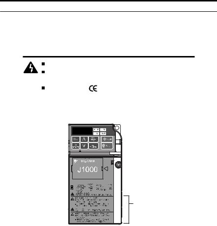
u Drive Label Warnings
Always heed the warning information listed in Figure i.1 in the position shown in Figure i. 2.
 WARNING Risk of electric shock.
Read manual before installing.
Wait 1 minute for capacitor discharge after disconnecting power supply.
To conform to requirements, make sure to ground the supply neutral for 400V class.
Figure i.1 Warning Information
Warning
Label
Figure i.2 Warning Information Position
YASKAWA ELECTRIC TOEP C710606 26D YASKAWA AC Drive – J1000 Quick Start Guide |
15 |

i.2 General Safety
u Warranty Information
n Restrictions
The drive was not designed or manufactured for use in devices or systems that may directly affect or threaten human lives or health.
Customers who intend to use the product described in this manual for devices or systems relating to transportation, health care, space aviation, atomic power, electric power, or in underwater applications must first contact their Yaskawa representatives or the nearest Yaskawa sales office.
This product has been manufactured under strict quality-control guidelines. However, if this product is to be installed in any location where failure of this product could involve or result in a life-and-death situation or loss of human life or in a facility where failure may cause a serious accident or physical injury, safety devices must be installed to minimize the likelihood of any accident.
u Quick Reference
Run a Motor of One-Frame Larger Capacity
When using this drive for variable torque loads such as fans and pumps, a motor one frame size larger can be used.
Know the Details of Safety Measures
The functions listed below affect the safe operation of the drive. Ensure that the settings fit the application requirements prior to operation.
Safe operations. Run by power on. Parameter setting b1-17.
LED operator stop key priority selection. Parameter o2-02.
Enter press required after changing the keypad frequency reference. Parameter o2-05.
Operation interlock when program mode is selected. Parameter b1-08.
Standards Compliance
Refer to European Standards on page 245 and Refer to UL Standards on page 254.
16 |
YASKAWA ELECTRIC TOEP C710606 26D YASKAWA AC Drive – J1000 Quick Start Guide |

1
Receiving
This chapter describes the proper inspections to perform after receiving the drive and illustrates the different enclosure types and components.
1.1 |
SECTION SAFETY............................................. |
18 |
1.2 |
MODEL NUMBER AND NAMEPLATE CHECK. . . |
19 |
1.3 |
COMPONENT NAMES....................................... |
22 |
YASKAWA ELECTRIC TOEP C710606 26D YASKAWA AC Drive – J1000 Quick Start Guide |
17 |

1.1 Section Safety
1.1Section Safety
 CAUTION
Do not carry the drive by the front cover.
Failure to comply may cause the main body of the drive to fall, resulting in minor or moderate injury.
NOTICE
Observe proper electrostatic discharge procedures (ESD) when handling the drive and circuit boards.
Failure to comply may result in ESD damage to the drive circuitry.
A motor connected to a PWM drive may operate at a higher temperature than a utilityfed motor and the operating speed range may reduce motor cooling capacity.
Ensure that the motor is suitable for drive duty and/or the motor service factor is adequate to accommodate the additional heating with the intended operating conditions.
18 |
YASKAWA ELECTRIC TOEP C710606 26D YASKAWA AC Drive – J1000 Quick Start Guide |
1.2Model Number and Nameplate Check
1.2Model Number and Nameplate Check
Please perform the following tasks after receiving the drive:
•Inspect the drive for damage.
If the drive appears damaged upon receipt, contact the shipper immediately.
•Verify receipt of the correct model by checking the information on the nameplate.
•If you have received the wrong model or the drive does not function properly, contact your supplier.
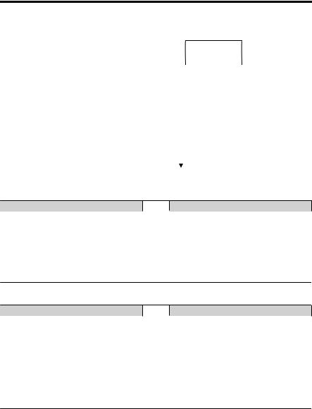
u Nameplate
|
|
|
|
|
|
|
|
|
|
|
|
|
|
|
|
|
A |
|
|
||
I |
|
|
|
|
|
|
MODEL |
: |
CIMR-J |
|
|
|
|
|
|
|
|
|
|
||
|
|
|
|
|
|
|
|
|
|
|
|
|
|
|
|
||||||
H |
MAX APPLI. MOTOR : 3.5A/3.0A |
REV : |
A |
|
|
|
|
|
|
||||||||||||
INPUT |
: AC3PH 200-240V 50 / 60Hz 2.7A / 1.4A |
IND.CONT.EQ. |
|
||||||||||||||||||
G |
|
||||||||||||||||||||
OUTPUT : AC3PH 0-240V 0-400Hz 1.2A / 0.8A |
7J48 |
B |
|||||||||||||||||||
F |
|
|
|
|
MASS |
: 0.9 kg |
|
|
|
|
|
||||||||||
|
|
|
|
|
|
|
|
|
|
|
|
|
|||||||||
|
|
|
|
O / N |
: |
|
|
|
|
|
|
|
|
|
|
|
|||||
|
|
|
|
|
|
|
|
|
|
|
|
|
|
||||||||
E |
|
|
S / N |
: |
|
|
PASS |
|
|
|
|
|
|||||||||
|
|
|
|
|
|
|
|
||||||||||||||
|
|
|
|
|
|
|
FILE NO |
: E131457 |
IP20 |
|
|
|
|
|
|||||||
|
|
|
|
|
|
|
|
|
|
|
|
|
|||||||||
|
|
|
D |
|
|
|
|
YASKAWA ELECTRIC CORPORATION |
|
MADE IN JAPAN |
|
|
|
|
|
|
|||||
|
|
|
|
|
|
|
2-1 Kurosaki-shiroishi, Yahatanishi-Ku, Kitakyushu 806-0004 Japan |
|
|
|
|
|
|||||||||
|
|
|
|
|
|
|
|
|
|
|
|
||||||||||
C
Receiving
1
A – Normal Duty Amps / |
F – Lot number |
Heavy Duty Amps |
G – Output specifications |
B – Software version |
H – Input specifications |
C – Enclosure type |
I – AC drive model |
D – Address <1> |
|
E – Serial number |
|
Figure 1.1 Nameplate Information Example
<1> The address of the head office of Yaskawa Electric Corporation (responsible for product liability) is shown on the nameplate.
YASKAWA ELECTRIC TOEP C710606 26D YASKAWA AC Drive – J1000 Quick Start Guide |
19 |
1.2 Model Number and Nameplate Check
CIMR - J |
U 2 |
|
A |
0001 |
|
|
|
B |
A |
|
A |
||||||||||||||||||||||||||||||
|
|
|
|
|
|
|
|
|
|
|
|
|
|
|
|
|
|
|
|
|
|
|
|
|
|
|
|
|
|
|
|
|
|
|
|
|
|
|
|
|
|
|
|
|
|
|
|
|
|
|
|
|
|
|
|
|
|
|
Customized |
|
|
|
|
|
|
|
|
|
|
|
|
|
|
|
|
|
|
|
|||||
Drive |
J1000 |
|
|
|
|
|
|
|
|
|
|
|
No. |
Enclosure Type |
|
|
|
|
|
|
|||||||||||||||||||||
|
|
|
|
|
|
|
No. |
|
|
|
|
|
|
|
Design |
||||||||||||||||||||||||||
|
|
|
|
Series |
|
|
|
|
|
|
|
|
|
Specifications |
|
|
|
|
|
|
|
IP20/Open- |
|
|
|
|
Revision |
||||||||||||||
|
|
|
|
|
|
|
|
|
|
|
|
|
|
|
|
A |
Standard model |
|
|
|
B |
|
|
|
|
|
Order |
||||||||||||||
|
|
No. |
|
|
Region |
|
|
|
|
|
|
|
|
|
|
|
Chassis |
|
|
|
|||||||||||||||||||||
|
|
|
|
Code |
|
|
|
|
|
|
|
|
|
|
|
|
|
|
|
|
|
|
|
|
|
|
|
|
|
|
|
|
|
|
|
|
|||||
|
|
|
|
|
|
|
|
|
|
|
|
|
|
|
|
|
|
|
|
|
|
|
|
|
|
|
|
|
|
|
|
|
|
|
|
|
|
||||
|
|
A |
|
|
Japan |
|
|
|
|
|
|
|
|
|
|
|
|
|
|
|
|
|
|
|
|
|
|
|
|
|
|
|
|
|
|
|
|
||||
|
|
|
|
|
|
|
|
|
|
|
|
|
|
|
|
|
|
No. |
|
Environmental |
|
|
|
|
|||||||||||||||||
|
|
B |
|
|
China |
|
|
|
|
|
|
|
|
|
|
|
|
|
|
|
|
|
|
Specification <1> |
|
|
|
|
|||||||||||||
|
|
|
|
|
|
|
|
|
|
|
|
|
|
|
|
|
|
|
|
|
|
|
|
|
|
|
|
|
|||||||||||||
|
|
|
|
|
|
|
|
|
|
|
|
|
|
|
|
|
|
|
|
|
|
A |
|
Standard |
|
|
|
|
|
|
|
||||||||||
|
|
C |
|
|
Europe |
|
|
|
|
|
|
|
|
|
|
|
|
|
|
|
|
|
|
|
|
|
|
|
|
|
|||||||||||
|
|
|
|
|
|
|
|
|
|
|
|
|
|
|
|
M |
|
Humidityand |
|
|
|
|
|||||||||||||||||||
|
|
T |
|
|
Asia |
|
|
|
|
|
|
|
|
|
|
|
|
|
|
|
|
|
|
|
|
|
|
|
dust-resistant |
|
|
|
|
||||||||
|
|
|
|
|
|
|
|
|
|
|
|
|
|
|
|
|
|
|
|
|
|
|
N |
|
Oil-resistant |
|
|
|
|
|
|
|
|||||||||
|
|
|
|
|
|
|
|
|
|
|
|
|
|
|
|
|
|
|
|
|
|
|
|
|
|
|
|
|
|
|
|
|
|
|
|||||||
|
|
U |
|
|
USA |
|
|
|
|
|
|
|
|
|
|
|
|
|
|
|
|
|
|
|
|
S |
|
Vibration-resistant |
|
|
|
||||||||||
|
|
|
|
|
|
|
|
|
|
|
|
|
|
|
|
|
|
|
|
|
|
|
|
|
|
|
|
|
|
|
|
|
|
|
|
|
|
|
|
|
|
|
|
|
|
|
|
No. |
|
|
|
|
|
|
Voltage Class |
|
|
|
|
|
|
|
|
|
|
|
|
|
|
|
|
|
|
|
|
|
|||||||
|
|
|
|
|
|
B |
|
|
1-phase, 200-240 Vac |
|
|
|
|
|
|
|
|
|
|
|
|
|
|
|
|
|
|
|
|
|
|||||||||||
|
|
|
|
|
|
2 |
|
|
3-phase, 200-240 Vac |
|
|
|
|
|
|
|
|
|
|
|
|
|
|
|
|
|
|
|
|
|
|||||||||||
|
|
|
|
|
|
4 |
|
|
|
3-phase, 380-480 Vac |
|
|
|
|
|
|
|
|
|
|
|
|
|
|
|
|
|
|
|
|
|
||||||||||
|
|
|
|
|
|
|
|
|
|
|
|
|
|
|
|
|
|
Refer to the tables below. |
|
|
|
|
|
|
|
||||||||||||||||
n Single-Phase 200 V
Normal Duty
No. |
Max. Motor |
Rated Output |
|
Capacity kW |
Current A |
||
|
|||
0001 |
0.2 |
1.2 |
|
0002 |
0.4 |
1.9 |
|
|
|
|
|
0003 |
0.75 |
3.3 |
|
0006 |
1.1 |
6.0 |
|
0010 |
2.2 |
9.6 |
|
|
|
|
Heavy Duty
No. |
Max. Motor |
Rated Output |
|
Capacity kW |
Current A |
||
|
|||
0001 |
0.1 |
0.8 |
|
0002 |
0.2 |
1.6 |
|
|
|
|
|
0003 |
0.4 |
3.0 |
|
0006 |
0.75 |
5.0 |
|
0010 |
1.5 |
8.0 |
|
|
|
|
n Three-Phase 200 V
Normal Duty
No. |
Max Motor |
Rated Output |
|
Capacity kW |
Current A |
||
|
|||
0001 |
0.2 |
1.2 |
|
0002 |
0.4 |
1.9 |
|
0004 |
0.75 |
3.5 |
|
|
|
|
|
0006 |
1.1 |
6.0 |
|
0010 |
2.2 |
9.6 |
|
0012 |
3.0 |
12.0 |
|
|
|
|
|
0020 |
5.5 |
19.6 |
|
|
|
|
Heavy Duty
No. |
Max Motor |
Rated Output |
|
Capacity kW |
Current A |
||
|
|||
0001 |
0.1 |
0.8 |
|
0002 |
0.2 |
1.6 |
|
0004 |
0.4 |
3.5 |
|
|
|
|
|
0006 |
0.75 |
6.0 |
|
0010 |
1.5 |
9.6 |
|
0012 |
2.2 |
12.0 |
|
|
|
|
|
0020 |
3.7 |
17.5 |
|
|
|
|
20 |
YASKAWA ELECTRIC TOEP C710606 26D YASKAWA AC Drive – J1000 Quick Start Guide |
1.2 Model Number and Nameplate Check
n Three-Phase 400 V
Normal Duty
No. |
Max. Motor |
Rated Output |
|
Capacity kW |
Current A |
||
|
|||
0001 |
0.4 |
1.2 |
|
0002 |
0.75 |
2.1 |
|
|
|
|
|
0004 |
1.5 |
4.1 |
|
0005 |
2.2 |
5.4 |
|
0007 |
3.0 |
6.9 |
|
|
|
|
|
0009 |
3.7 |
8.8 |
|
0011 |
5.5 |
11.1 |
|
|
|
|
Heavy Duty
No. |
Max. Motor |
Rated Output |
|
Capacity kW |
Current A |
||
|
|||
0001 |
0.2 |
1.2 |
|
0002 |
0.4 |
1.8 |
|
|
|
|
|
0004 |
0.75 |
3.4 |
|
0005 |
1.5 |
4.8 |
|
0007 |
2.2 |
5.5 |
|
|
|
|
|
0009 |
3.0 |
7.2 |
|
0011 |
3.7 |
9.2 |
|
|
|
|
Receiving
1
YASKAWA ELECTRIC TOEP C710606 26D YASKAWA AC Drive – J1000 Quick Start Guide |
21 |
1.3 Component Names
1.3Component Names
This section illustrates drive components in the IP20/Open-Chassis models.
Refer to NEMA Type 1 Kit on page 193 for information on using the NEMA Type 1 Kit option to create a NEMA Type 1 rating.
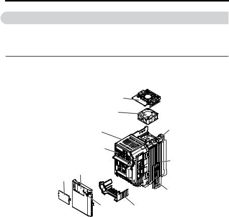
u IP20/Open-Chassis
nSingle-Phase AC 200 V BA0001B to BA0003B Three-Phase AC 200 V 2A0001B to 2A0006B
|
|
K |
|
|
J |
|
I |
A |
|
|
|
|
H |
|
|
|
B |
F |
G |
|
|
|
|
|
|
C |
|
E |
D |
A – Mounting hole |
G – Front cover |
|
B – Heatsink |
|
H – LED operator Refer to |
C – Cable cover |
Using the Digital LED |
|
D – Terminal cover |
Operator on page 73 |
|
E – Front cover screw |
I – Case |
|
F – Option connector cover |
J – Cooling fan <1> |
|
|
|
K – Fan cover <1> |
Figure 1.2 Exploded View of IP20/Open-Chassis Type Components
(Model 2A0006B)
<1> Models BA0001B to BA0003B and 2A0001B to 2A0004B do not have a cooling fan or a cooling fan cover.
22 |
YASKAWA ELECTRIC TOEP C710606 26D YASKAWA AC Drive – J1000 Quick Start Guide |
1.3 Component Names
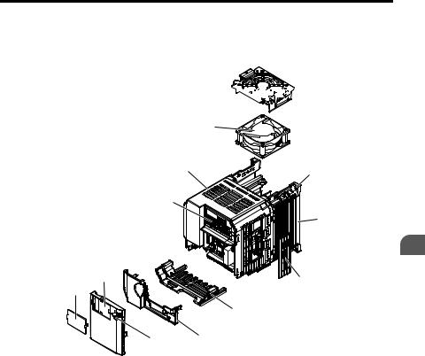
nSingle-Phase AC 200 V BA0006B to BA0010B Three-Phase AC 200 V 2A0010B to 4A0020B Three-Phase AC 400 V 4A0001B to 4A0011B
L 


|
|
K |
|
J |
A |
|
|
|
|
I |
|
|
|
B |
H |
|
C |
G |
|
|
|
|
D |
F |
|
E |
|
|
|
A – Mounting hole |
|
G – Option connector cover |
B – Heatsink |
|
H – Front cover |
C – Cable cover |
|
I – LED operator Refer to |
D – Terminal cover |
|
Using the Digital LED |
E – Bottom cover |
|
Operator on page 73 |
F – Front cover screw |
|
J – Case |
|
|
K – Cooling fan <1> |
|
|
L – Fan cover <1> |
Figure 1.3 Exploded view of IP20/Open-Chassis Type Components (Model 2A0012B)
<1> Models BA0006B and 4A0001B to 4A0004B do not have a cooling fan or a cooling fan cover.
Receiving
1
YASKAWA ELECTRIC TOEP C710606 26D YASKAWA AC Drive – J1000 Quick Start Guide |
23 |

1.3 Component Names
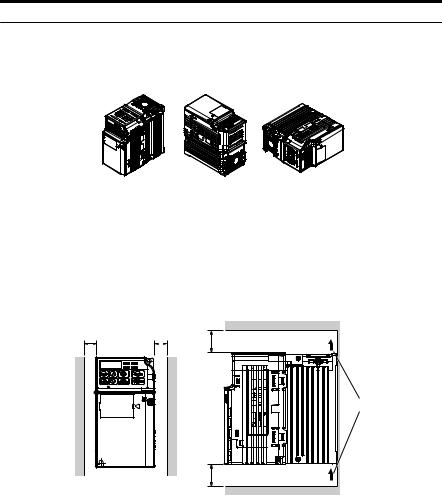
u Front Views
|
2A0006B |
2A0012B |
|
|
A |
A |
|
G |
B |
G |
|
B |
|||
|
C |
C |
|
F |
F |
||
D |
|||
D |
|||
|
|||
|
|
||
|
E |
E |
A– DIP switch S1 Refer to DIP Switch S1 Analog
Input Signal Selection on page 62
B – DIP switch S3 Refer to Sinking/Sourcing Mode Switch on page 59
C– Control circuit terminal
Refer to Control Circuit Wiring on page 52
D– Main circuit terminal
Refer to Wiring the Main Circuit Terminal on page 51
E – Ground terminal
F – Terminal cover
G– Option unit connector
Refer to Options on page 198
Figure 1.4 Front Views of Drives
24 |
YASKAWA ELECTRIC TOEP C710606 26D YASKAWA AC Drive – J1000 Quick Start Guide |

2
Mechanical
Installation
This chapter explains how to properly mount and install the drive.
2.1 |
SECTION SAFETY............................................. |
26 |
2.2 |
MECHANICAL INSTALLATION.......................... |
29 |
YASKAWA ELECTRIC TOEP C710606 26D YASKAWA AC Drive – J1000 Quick Start Guide |
25 |

2.1 Section Safety
2.1Section Safety
 WARNING
Fire Hazard
Provide sufficient cooling with a fan or air conditioning unit when installing the drive inside an enclosed panel or cabinet.
Failure to comply could result in overheating and fire.
The airflow over an IP20/Open-Chassis drive should be less than 50 °C, while an IP20/ NEMA Type 1 drive using the NEMA Type 1 Kit option should have an airflow cooler than 40 °C.
 CAUTION
Crush Hazard
Do not carry the drive by the front cover.
Failure to comply may result in minor or moderate injury from the main body of the drive falling.
26 |
YASKAWA ELECTRIC TOEP C710606 26D YASKAWA AC Drive – J1000 Quick Start Guide |

2.1 Section Safety
NOTICE
Observe proper electrostatic discharge (ESD) procedures when handling the drive.
Failure to comply could result in ESD damage to the drive circuitry.
It may be difficult to perform maintenance on the cooling fans of drives installed in a vertical row inside an enclosure.
Ensure adequate spacing at the top of the drive to perform cooling fan replacement when required.
Operating the motor in the low-speed range diminishes the cooling effects, increases motor temperature, and may lead to motor damage by overheating.
Reduce the motor torque in the low-speed range whenever using a standard blower cooled motor. If 100% torque is required continuously at low speed, consider using a special drive or vector motor. Select a motor that is compatible with the required load torque and operating speed range.
Do not operate motors above the maximum rated RPM.
Failure to comply may lead to bearing or other mechanical motor failures.
The speed range for continuous operation differs according to the lubrication method and motor manufacturer.
If the motor is to be operated at a speed higher than the rated speed, consult with the manufacturer.
Continuously operating an oil-lubricated motor in the low-speed range may result in burning.
Mechanical Installation
2
YASKAWA ELECTRIC TOEP C710606 26D YASKAWA AC Drive – J1000 Quick Start Guide |
27 |

2.1 Section Safety
NOTICE
When the wiring distance is greater than 100 meters, pay special attention to the motor insulation voltage or use a drive-rated motor.
Failure to comply could lead to motor winding failure.
Motor vibration may increase when operating a machine in variable-speed mode, if that machine previously operated at a constant speed.
Install vibration-proof rubber on the motor base or use the frequency jump function to skip a frequency resonating the machine.
The motor may require more acceleration torque with drive operation than with a commercial power supply.
Set a proper V/f pattern by checking the load torque characteristics of the machine to be used with the motor.
The rated input current of submersible motors is higher than the rated input current of standard motors.
Select an appropriate drive according to its rated output current. When the distance between the motor and drive is long, use a cable thick enough to connect the motor to the drive to prevent motor torque reduction.
When using an explosion-proof motor, it must be subject to an explosion-proof test in conjunction with the drive.
This is also applicable when an existing explosion-proof motor is to be operated with the drive. Since the drive itself is not explosion-proof, always install it in a safe place.
Do not use a drive for a single-phase motor.
Replace the motor with a three-phase motor.
If an oil-lubricated gearbox or speed reducer is used in the power transmission mechanism, oil lubrication will be affected when the motor operates only in the low speed range.
The power transmission mechanism will make noise and experience problems with service life and durability if the motor is operated at a speed higher than the rated speed.
28 |
YASKAWA ELECTRIC TOEP C710606 26D YASKAWA AC Drive – J1000 Quick Start Guide |

2.2 Mechanical Installation
2.2Mechanical Installation
This section outlines specifications, procedures, and environment for proper mechanical installation of the drive.
u Installation Environment
To help prolong the optimum performance life of the drive, install the drive in the proper environment. The table below provides a description of the appropriate environment for the drive.
|
|
Table 2.1 Installation Environment |
|
Environment |
|
Conditions |
|
Installation Area |
Indoors |
||
|
|
||
|
IP20/NEMA Type 1 enclosure: -10 °C to +40 °C (14 °F to 104 °F) |
||
|
IP20/IP00 Open-Chassis enclosure: -10 °C to +50 °C (14 °F to 122 °F) |
||
Ambient |
Finless Type: IP20 enclosure: -10 °C to +50 °C (14 °F to 122 °F) |
||
Drive reliability improves in environments without wide temperature fluctuations. |
|||
Temperature |
|||
When using an enclosure panel, install a cooling fan or air conditioner in the area to ensure |
|||
|
|||
|
that the air temperature inside the enclosure does not exceed the specified levels. |
||
|
Do not allow ice to develop on the drive. |
||
Humidity |
95% RH or less and free of condensation |
||
Storage Temperature |
-20 °C to +60 °C (-4 °F to +104 °F) |
||
|
|
||
|
Install the drive in an area free from: |
||
|
• oil mist and dust |
||
|
• metal shavings, oil, water or other foreign materials |
||
|
• |
radioactive materials |
|
Surrounding Area |
• combustible materials (e.g., wood) |
||
|
• harmful gases and liquids |
||
|
• |
excessive vibration |
|
|
• |
chlorides |
|
|
• |
direct sunlight |
|
|
|
||
Altitude |
Up to 1000 meters without derating; up to 3000 meters with output current, ambient |
||
temperature, and voltage derating. |
|||
|
|||
Vibration |
10 to 20 Hz at 9.8 m/s2 |
||
20 to 55 Hz at 5.9 m/s2 |
|||
|
|||
Orientation |
Install the drive vertically to maintain maximum cooling effects. |
||
NOTICE: Prevent foreign matter such as metal shavings or wire clippings from falling into the drive during installation and project construction. Failure to comply could result in damage to the drive. Place a temporary cover over the top of the drive during installation. Remove the temporary cover before startup, as the cover will reduce ventilation and cause the drive to overheat.
NOTICE: Avoid placing drive peripheral devices, transformers, or other electronics near the drive. Failure to comply could result in erroneous operation. If such devices must be used in close proximity to the drive, take proper steps to shield the drive from noise.
Mechanical Installation
2
YASKAWA ELECTRIC TOEP C710606 26D YASKAWA AC Drive – J1000 Quick Start Guide |
29 |
2.2 Mechanical Installation
u Installation Orientation and Spacing
Install the drive upright as illustrated in Figure 2.1 to maintain proper cooling.
A B B
A – Correct |
B – Incorrect |
Figure 2.1 Correct Installation Orientation
n Single Drive Installation
Figure 2.2 explains the required installation spacing to maintain sufficient space for airflow and wiring. Install the heatsink against a closed surface to avoid diverting cooling air around the heatsink.
Side Clearance |
Top/Bottom Clearance |
A |
A |
C |
|
|
C
A – 30 mm minimum
B – Airflow direction
B |
C – 100 mm minimum |
Figure 2.2 Correct Installation Spacing
Note: The space required on the left and right sides of the drive are the same for IP20/Open-Chassis drives and IP20/NEMA Type 1 drives using the NEMA Type 1 Kit option.
30 |
YASKAWA ELECTRIC TOEP C710606 26D YASKAWA AC Drive – J1000 Quick Start Guide |
Loading...