Yaskawa J7, J1000 User Manual
Product Transition Guide – J7 to J1000
Product Transition Guide
J7 to J1000
Doc#: PL.J1000.01 |
Copyright Yaskawa Electric America, Inc.♥2008 |
www.yaskawa.com |
August 1, 2008 |
1 of 19 |

Product Transition Guide – J7 to J1000
Subject: Transition Guide |
Product: J1000 |
Document: PL.J1000.01 |
|
||
|
|
|
|
||
Title: Product Transition Guide – J7 to J1000 |
|
|
|||
|
|
|
|
|
|
|
|
|
Table of Contents |
|
|
1.0 |
APPLICABLE DRIVES ……………………………………………………………….. |
3 |
|||
2.0 |
DRIVE REPLACEMENT CHECKLIST ……………………………………………… |
4 |
|||
3.0 |
RATINGS SUMMARY ………………………………………………………………… |
5 |
|||
4.0 |
TERMINALS …………………………………………………………………………… |
6 |
|||
|
4.1 |
Main Circuit Terminals ……………………………………………………….. |
6 |
||
|
4.2 |
Control Terminals, Signal Levels ………………………………………….. |
6 |
||
|
4.3 |
DIP Switches …………………………………………………………………... |
7 |
||
|
4.4 |
Main Terminal Size / Electric Wire Differences …………………………. |
7 |
||
|
4.5 |
Control Terminal and Wire Sizes …………………………………………... |
9 |
||
5.0DIMENSIONS…………………………………………………………………...……... 10
6.0OPTION REPLACEMENTS …………………………………………………………. 11
7.0PARAMETER SETTINGS ……………………………………………………………. 12
7.1 |
Parameter Correspondence for Drive Replacement ………………...…. |
12 |
7.2 |
Parameter Differences ……………………………………………………….. |
18 |
7.3 |
Special Software Replacement ………………...…………………………... |
18 |
8.0REVISION HISTORY …………………………………………………………………. 19
9.0 REFERENCES ………………………………………………………………………… 19
Doc#: PL.J1000.01 Copyright Yaskawa Electric America, Inc.♥2008 |
www.yaskawa.com |
August 1, 2008 |
2 of 19 |

Product Transition Guide – J7 to J1000
Subject: Transition Guide |
Product: J1000 |
Document: PL.J1000.01 |
|
|
|
Title: Product Transition Guide – J7 to J1000 |
|
|
|
|
|
1.0 Applicable Drives
This document describes the substitution of the following drives:
Original Drive: CIMR-J7xMxxxx, CIMR-J7xUxxx, or JDxxxx
Spec: |
xxxx0 (IP20) |
Software Version: |
Standard: 001x, 002x |
Replacement: CIMR-JUxAxxxxBxx |
|
Spec: |
CIMR-JUxAxxxxBxx (A-Standard model) |
Software Version: |
PRG: 10xx |
This replacement J1000 drive must be selected using the J1000 Heavy Duty rating.
The description is not valid for drives with other specifications or firmware installed.
Doc#: PL.J1000.01 Copyright Yaskawa Electric America, Inc.♥2008 |
www.yaskawa.com |
August 1, 2008 |
3 of 19 |

Product Transition Guide – J7 to J1000
Subject: Transition Guide |
Product: J1000 |
Document: PL.J1000.01 |
|||||
|
|
|
|
|
|
|
|
Title: Product Transition Guide – J7 to J1000 |
|
|
|||||
|
|
|
|
|
|
|
|
2.0 Drive Replacement Checklist |
|
|
|||||
|
|
|
|
|
|
|
|
|
|
Item |
|
|
Checkpoints |
|
Checked? |
|
|
|
|
Digital Operator Panel |
|
|
|
|
|
|
|
Does the digital operator panel need to be mounted in the same location as |
|
||
|
|
|
|
before? |
|
|
|
|
|
|
|
- If necessary, attempt to mount the operator panel at the same location as |
|
||
|
|
|
|
before. |
|
|
|
|
|
Basic |
|
Was a remote operator connected to the old unit? |
|
|
|
|
|
|
|
- If so, do not attempt to connect the old remote operator panel to the J1000. |
|
||
|
|
|
|
Refer to part 6 of this document for option replacements. |
|
||
|
|
|
|
Special Specifications |
|
|
|
|
|
|
|
Check the installed drive’s specifications to make sure that it is compliant with the |
|
||
Hardware |
|
|
|
standard specifications (no special firmware, etc.). |
|
|
|
|
|
|
Wire Length |
|
|
|
|
|
|
|
|
In the J7 drive, the main terminals are located at the top of the drive. The J1000 |
|
||
|
|
Main and |
|
drive has all main terminals located at the bottom of the drive. Check to assure |
|
||
|
|
Control |
|
that all cables are long enough to be connected without tension to the new drive. |
|
||
|
|
|
Main Circuit Wires and Terminal Specifications |
|
|
||
|
|
Terminals |
|
|
|
||
|
|
|
Compare the occupied terminals of the old drive to the new drive’s terminals |
|
|||
|
|
|
|
(shape, size, etc.). Check that all wires fit in the new drive’s terminals, refer to part |
|
||
|
|
|
|
4 of this document. |
|
|
|
|
|
|
|
Check Software Version or for Special Software |
|
|
|
|
|
Software |
|
Check the software number in the old drive to be sure that it can be replaced by |
|
||
|
|
|
the J1000 drive. Refer to part 7.3 of this document. |
|
|
||
|
|
Version |
|
|
|
||
|
|
|
- Ask your Yaskawa representative for help in identifying the software installed |
|
|||
|
|
|
|
|
|||
|
|
|
|
on the drive that must be replaced and for additional replacement information. |
|
||
Software |
|
|
|
Check the Parameter Settings |
|
|
|
|
|
|
Check the parameter settings of the J7 drive and perform a parameter transition to |
|
|||
|
|
Parameter |
|
the new parameters following part 7 of this document. Contact your Yaskawa |
|
||
|
|
|
|
representative if there is special software installed or if a parameter is not |
|
||
|
|
|
|
mentioned in this document. |
|
|
|
|
|
Communi- |
|
Is an Option Card Installed? |
|
|
|
|
|
|
Check if any communication card options are installed. |
|
|||
|
|
cation |
|
- J7 options are NOT compatible with the J1000 drive and must be replaced. |
|
||
|
|
Option |
|
- Communication cable connectors from J7 options are compatible to the J1000 |
|
||
|
|
|
options without rewiring. |
|
|
||
|
|
|
|
|
|
||
Options, |
|
Reactors, |
|
Is an AC Reactor or DC Link Choke Installed? |
|
|
|
|
|
AC Reactors or DC Link Chokes installed on a J7 drive are compatible with the |
|
||||
Others |
|
Chokes |
|
|
|||
|
|
J1000 drive. |
|
|
|
||
|
|
Filters |
|
Is an EMC Filter Installed? |
|
|
|
|
|
|
Some EMC Filters installed on a J7 drive are compatible with the J1000 drive. For |
|
|||
|
|
|
|
details on filter replacements contact your Yaskawa representative. |
|
||
|
|
|
|
Extension Cables |
|
|
|
|
|
Cables |
|
The extension cables for remote operation used on a J7 drive are compatible with |
|
||
|
|
|
the J1000 drive. However, the remote operator and the remote operator interface |
|
|||
|
|
|
|
|
|||
|
|
|
|
are not compatible with the J1000 drive and must be replaced. |
|
||
•For questions on installation, parameter settings or detailed parameter/ function descriptions see the instruction manual. Other technical questions should be referred to your Yaskawa representative.
Doc#: PL.J1000.01 Copyright Yaskawa Electric America, Inc.♥2008 |
www.yaskawa.com |
August 1, 2008 |
4 of 19 |
Product Transition Guide – J7 to J1000
Subject: Transition Guide |
Product: J1000 |
Document: PL.J1000.01 |
|
|
|
Title: Product Transition Guide – J7 to J1000 |
|
|
|
|
|
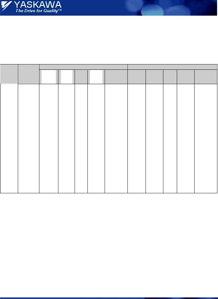
3.0 Ratings Summary |
|
|
|
|
|
|
|
|
|||
<1>, <3> |
|
|
|
|
|
|
|
|
|
|
|
|
Maximum |
|
|
J7 |
|
|
|
|
J1000 |
|
|
Voltage |
Motor |
Model |
Output |
|
Output |
Carrier |
Model |
Output |
|
Output |
Carrier |
Class |
Power |
No. |
Power |
HP |
Current |
Frequency |
No. |
Power |
HP |
Current |
Frequency |
|
(kW) |
J7xM x |
(kVA) |
|
(A) |
(kHz) |
JU x |
(kVA) |
|
(A) |
(kHz) |
|
|
|
0.1 |
B0P1 |
0.3 |
1/8 |
0.8 |
|
BA0001 |
0.3 |
1/8 |
0.8 |
|
|
Single |
|
0.2 |
B0P2 |
0.6 |
1/4 |
1.6 |
|
BA0002 |
0.6 |
1/4 |
1.6 |
|
|
Phase |
|
0.4 |
B0P4 |
1.1 |
1/2 |
3.0 |
10 |
BA0003 |
1.1 |
1/2 |
3.0 |
10 |
|
200 V |
|
|
|
|
|
|
|
|
|
|
|
|
0.75 |
B0P7 |
1.9 |
3/4 |
5.0 |
|
BA0006 |
1.9 |
3/4 & |
5.0 |
|
|||
|
|
|
|
||||||||||
|
|
|
|
|
|
& 1 |
|
|
|
|
1 |
|
|
|
|
|
1.5 |
B1P5 |
3.0 |
2 |
8.0 |
7.5 |
BA0010 |
3.0 |
2 |
8.0 |
8 |
|
|
|
0.1 |
20P1 |
0.3 |
1/8 |
0.8 |
|
2A0001 |
0.3 |
1/8 |
0.8 |
|
|
|
|
0.2 |
20P2 |
0.6 |
1/4 |
1.6 |
|
2A0002 |
0.6 |
1/4 |
1.6 |
|
|
Three- |
|
0.4 |
20P4 |
1.1 |
1/2 |
3.0 |
10 |
2A0004 |
1.1 |
1/2 |
3.0 |
10 |
|
|
0.75 |
20P7 |
1.9 |
3/4 |
5.0 |
|
2A0006 |
1.9 |
3/4 & |
5.0 |
|
|
|
Phase |
|
|
|
|||||||||
|
|
|
|
|
& 1 |
|
|
|
|
1 |
|
|
|
|
200 V |
|
|
|
|
|
|
|
|
|
|
||
|
|
1.5 |
21P5 |
3.0 |
2 |
8.0 |
7.5 |
2A0010 |
3.0 |
2 |
8.0 |
8 |
|
|
|
|
|||||||||||
|
|
|
2.2 |
22P2 |
4.2 |
3 |
11.0 |
2A0012 |
4.2 |
3 |
11.0 |
||
|
|
|
3.7 |
23P7 |
6.7 |
5 |
17.5 |
|
2A0020 |
6.7 |
5 |
17.5 |
|
|
|
|
0.2 |
40P2 |
0.9 |
1/2 |
1.2 |
|
4A0001 |
0.9 |
1/2 |
1.2 |
|
|
|
|
0.4 |
40P4 |
1.4 |
3/4 |
1.8 |
|
4A0002 |
1.4 |
3/4 |
1.8 |
|
|
Three- |
|
0.75 |
40P7 |
2.6 |
1 & |
3.4 |
|
4A0004 |
2.6 |
1 & 2 |
3.4 |
|
|
|
|
|
|
2 |
|
|
|
|
|
|
|
|
|
Phase |
|
|
|
|
|
7.5 |
|
|
|
|
8 |
|
|
|
1.5 |
41P5 |
3.7 |
3 |
4.8 |
4A0005 |
3.7 |
3 |
4.8 |
|||
|
400 V |
|
|
|
|||||||||
|
|
2.2 |
42P2 |
4.2 |
3 |
5.5 |
|
4A0007 |
4.2 |
3 |
5.5 |
|
|
|
|
|
|
|
|||||||||
|
|
|
2.2 |
42P2 |
4,2 |
3 |
5,5 |
|
4A0009 |
5.5 |
4 |
7.2 |
|
|
|
|
3.7 |
43P7 |
6.6 |
5 |
8.6 |
|
4A0011 |
7.0 |
5 |
9.2 |
|
Doc#: PL.J1000.01 Copyright Yaskawa Electric America, Inc.♥2008 |
www.yaskawa.com |
August 1, 2008 |
5 of 19 |
Product Transition Guide – J7 to J1000
Subject: Transition Guide |
Product: J1000 |
Document: PL.J1000.01 |
|
|
|
Title: Product Transition Guide – J7 to J1000 |
|
|
|
|
|
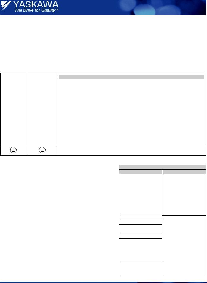
4.0 Terminals
4.1 Main Circuit Terminals
Note: The J7 and J1000 drives may have different terminal sizes (depending on capacity); therefore, the terminals must be
carefully checked before replacement. The main terminal functionality has not been changed.
J7 Main |
J1000 Main |
Note |
|
Terminals |
Terminals |
||
|
|||
R / L 1 |
R / L 1 |
Power supply connection. |
|
S / L2 |
S / L2 |
Note: |
|
|
|
In the J7 drive the power supply terminals are located at the top of the drive. In the J1000 |
|
T / L 3 |
T / L 3 |
the power supply terminals are located at the bottom of the drive. Cables must fit without |
|
|
|
tension (replace or extend if needed). |
|
U / T1 |
U / T1 |
|
|
V / T2 |
V / T2 |
Drive Output |
|
W / T3 |
W / T3 |
|
|
- |
B1 |
Braking resistor or external braking chopper connection. |
|
- |
B2 |
Braking resistor connection. |
|
+1 |
+1 |
DC Link Choke connection, DC Power Supply input. |
|
+2 |
+2 |
||
|
|||
+1 |
+1 |
DC Power Supply input, external braking transistor module connection. |
|
|
|
——
Grounding Terminal: For 200 V class: 100 Ω or less
For 400 V class: 10 Ω or less
4.2 Control Terminals, Signal Levels
|
Terminal |
|
Function |
|
||||
|
|
|||||||
|
J7 |
|
J1000 |
|
|
|||
|
|
|
|
|
||||
|
S1 |
|
|
|
Multi-function input 1 |
|||
|
|
|
|
(1: Run forward, 0: Stop) |
||||
|
|
|
|
|
|
|
||
|
S2 |
|
|
|
Multi-function input 2 |
|||
|
|
|
|
(1: Run reverse, 0: Stop) |
||||
|
|
|
|
|
|
|
||
|
S3 |
|
|
|
Multi-function input 3 |
|||
|
|
|
|
(J7: Fault Reset / J1000: Ext. Fault) |
||||
|
|
|
|
|
|
|
||
|
S4 |
|
|
|
Multi-function input 4 |
|||
|
|
|
|
(J7: Ext. Fault / J1000: Fault Reset) |
||||
|
|
|
|
|
|
|
||
|
S5 |
|
|
|
Multi-function input 5 (Multi speed 1) |
|||
|
SC |
|
|
|
Multi-function input common. |
|||
|
FS |
|
+V |
|
Analog input power supply. |
|||
|
FR |
|
|
A1 |
|
|
Analog input 1 |
|
|
|
|
|
|
(Frequency Reference) |
|||
|
|
|
|
|
|
|
||
|
FC |
|
|
AC |
|
|
Analog input common. |
|
|
MA |
|
|
|
Change over contact output (NO). |
|||
|
|
|
|
(Fault) |
||||
|
|
|
|
|
|
|
||
|
MB |
|
|
|
Change over contact output (NC). |
|||
|
|
|
|
(Fault) |
||||
|
|
|
|
|
|
|
||
|
MC |
|
|
|
Change over contact output common. |
|||
|
AM |
|
|
|
Analog output. |
|||
|
AC |
|
|
|
Analog output GND |
|||
|
Signal Level |
J7 |
J1000 |
Photo coupler isolation |
Photo coupler isolation |
+24 Vdc, 8 mA |
+24 Vdc, 8 mA |
— |
|
— |
+12 Vdc, max. 20 mA |
|
+10.5 Vdc, max. 20 mA |
0 ~ +10 Vdc (20 kΩ) |
|
0 ~ +10 Vdc (20 kΩ) |
0 or 4-20 mA (250 Ω) |
|
0 or 4-20 mA (250 Ω) |
|
0 V |
|
Maximum Load |
|
Maximum Load |
250 Vac , 10 mA ~ 1A |
|
250 Vac , 10 mA ~ 1A |
30 Vdc, 10 mA ~ 1 A |
|
30 Vdc, 10 mA ~ 1 A |
|
|
|
0 ~ +10 Vdc, |
|
0 ~ +10 Vdc, |
Maximum 2 mA |
|
maximum 2 mA |
Resolution 8 Bit |
|
Resolution 8 Bit |
Doc#: PL.J1000.01 Copyright Yaskawa Electric America, Inc.♥2008 |
www.yaskawa.com |
August 1, 2008 |
6 of 19 |
 Loading...