


Yaskawa Electric
America
Unit Troubleshooting Manual
Section One:
Introduction & Checks Without Power
GPD 506/P5 and GPD 515/G5
(0.4 ~ 160kW)
PP.P5G5.01.Troubleshoot
Page 1
Rev. 06/11/2003

Introduction
This manual is divided into three sections:
Section One is called “Checks Without Power”; it explains the steps used to check out the inverter, with no power applied, using an ohmmeter.
Section Two is called “Power Checks”; this section explains a systematic method of applying power to the inverter and checking various points on the inverter to verify proper operation.
Section Three is called “Fault Codes”; this section explains the fault indications, possible causes, and corrective actions.
•This document can also be used with GPD 505/P5 inverters, but some part numbers may be different.
•In this document, test and check point details pertaining to the GPD 506/P5 can also be considered for the GPD 505/P5 unless otherwise noted.
•Mfg. part numbers and YEA code numbers listed in this manual are subject to change.
PP.P5G5.01.Troubleshoot
Page 2
Rev. 06/11/2003
Introduction
Decoding the model number
CIMR-G5U23P7
Inverter 
Product |
|
Model Number |
|
|
|
GPD 515/G5 |
Voltage Rating |
|
GPD 506/P5 |
||
Specification |
2 - 230V 3 phase |
|
U or M - Americas |
4 |
- 460V 3 phase |
A - Japan/Asia |
5 |
– 600V 3 phase |
E - Europe |
|
|
PP.P5G5.01.Troubleshoot
Page 3
Rev. 06/11/2003
Inverter Markings
On every Yaskawa inverter is an inspection stamp and lot number. The information contained in the inspection stamp is the date and year that the inverter was tested. The lot number contains more detail about when the inverter was produced. The date stamp information and lot number are needed when submitting a warranty claim to Yaskawa.
|
|
|
|
|
|
Assembled in the U.S.A. |
|||||||
Inspection Stamp |
|
YEA Production |
|||||||||||
|
|
|
PRD |
|
Manufacture Date |
||||||||
96 3. 31 |
|
||||||||||||
|
|
|
|
|
|
|
|
|
|||||
|
|
|
INSP2 |
|
Inspector Number |
||||||||
|
|
|
|
|
|
||||||||
Lot Number |
|
U-9603250-3 |
|||||||||||
|
|
|
|
|
|
||||||||
Manufactured in U.S.A. |
|
|
|
|
|
|
|
|
|
Unit Number in Work Order |
|||
|
|
|
|
|
|
|
|
|
|||||
|
|
|
|
|
|
||||||||
Year |
|
|
|
|
|
|
|
|
|
|
Computer Generated Number |
||
|
|
|
|
|
|
|
|
|
|
||||
Month |
|
|
|
|
|
|
|
|
|
|
|||
|
|
|
|
|
|
|
|
|
|
||||
PP.P5G5.01.Troubleshoot
Page 4
Rev. 06/11/2003

Inverter Markings
On every Yaskawa inverter is an inspection stamp and lot number. The information contained in the inspection stamp is the date and year that the inverter was tested. The lot number contains more detail about when the inverter was produced. The date stamp information and lot number are needed when submitting a warranty claim to Yaskawa.
|
|
|
|
Manufactured in Japan |
|||||||
Inspection Stamp |
|
YEC Production |
|||||||||
|
INSP |
|
Manufacture Date |
||||||||
96 4. 11 |
|
||||||||||
|
|
|
|
|
|
|
|
|
|||
|
T.K |
|
Inspector |
||||||||
|
|
|
|
||||||||
Lot Number |
|
|
|
|
|
|
|
|
|
||
|
|
|
|
NR5GA09-573A-15 |
|||||||
Manufactured in Japan |
|
|
|
|
|
|
|
|
|
Month |
|
|
|
|
|
|
|
|
|
|
|||
|
|
|
|
|
|
|
|||||
|
|
|
|
|
|
|
|
|
|
|
Year |
|
|
|
|
|
|
|
|
|
|
|
|
PP.P5G5.01.Troubleshoot
Page 5
Rev. 06/11/2003
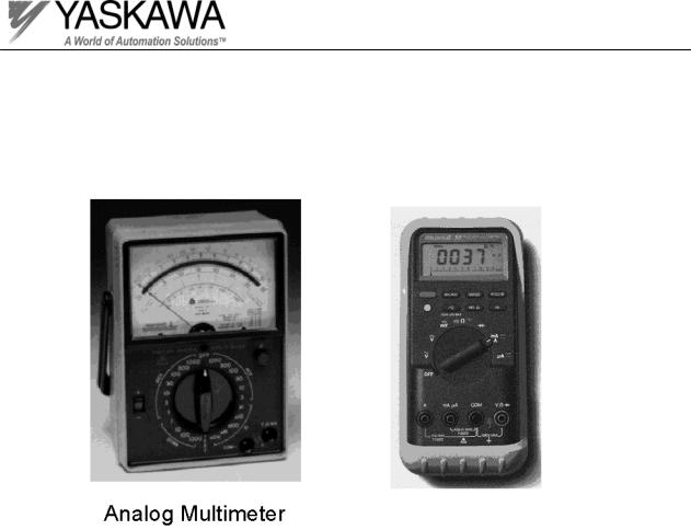
Test Equipment
The basic tools used for troubleshooting a Yaskawa inverter are as follows;
Digital Multimeter
PP.P5G5.01.Troubleshoot
Page 6
Rev. 06/11/2003
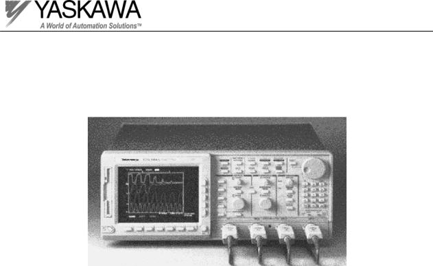
Test Equipment
An ungrounded Oscilloscope with a 10X and 100X probe.
A 30 watt, 500 ohm resistor.
PP.P5G5.01.Troubleshoot
Page 7
Rev. 06/11/2003
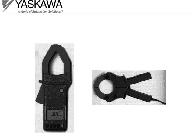
Test Equipment
AC Clamp-on
current probe
True RMS clamp meter
PP.P5G5.01.Troubleshoot
Page 8
Rev. 06/11/2003
Section One:
Checks Without Power
Unit Elementary Diagram Review |
. |
|
PP.P5G5.01.Troubleshoot
Page 9
Rev. 06/11/2003

Main Circuit Test Procedure 
This test procedure must be performed before making a repair.
TEST PROCEDURE CHECKLIST
Check box when completed
1. Check DC bus voltage.
2. Check input diodes.
3. Check soft charge resistor(s).
4. Check soft charge contactor.
5. Check DC bus fuse.
6. Check the braking circuit. (If internal)
7. Check output transistors.
8. Check snubber circuit.
9. Check the control power fuse.
10. Check the cooling fan(s).
11. Check the cooling fan(s) fuse.
PP.P5G5.01.Troubleshoot
Page 10
Rev. 06/11/2003
! WARNING
LETHAL VOLTAGES ARE PRESENT!
Before attempting any checks in this troubleshooting manual, make sure that the three phase power is disconnected and locked out. With power removed from the unit, the DC bus capacitors will stay charged for several minutes. The charge LED in the unit will glow red until the DC bus voltage is below 10 VDC. To ensure that the DC bus is completely discharged, measure between the positive and negative bus with a DC voltmeter set to the highest scale.
Checking the inverter for power
Test Equipment - DC voltmeter set to the highest scale
This test is a mandatory safety check! Before touching any components inside the inverter, perform the following test. Look at the charge LED on the inverter. If high voltage is present on the DC bus, the charge LED will glow red. As the DC bus capacitors discharge, the charge LED will fade out. There is a possibility that voltage will be present on the DC bus even when the charge LED is off. To determine if the DC bus is completely discharged, measure between the positive and negative portions of the DC bus with a DC voltmeter. Set the meter to it’s highest scale and place the positive lead onto the positive portion of the DC bus and place the negative lead onto the negative portion of the DC bus. If the measured voltage is below 10 VDC, you can safely work inside the unit.
PP.P5G5.01.Troubleshoot
Page 11
Rev. 06/11/2003
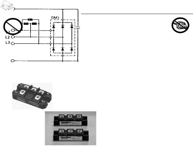
Input Diodes
On small horsepower models, the input diodes are located inside the power module PM1 or in a separate module labeled DM1. Larger horsepower models have separate 2-in-1 style diode modules. The input diodes rectify or transform the three-phase input AC voltage into a DC voltage. The DC voltage level is proportional to the input AC voltage and is the main reference voltage in the inverter called the DC Bus. The DC bus voltage should normally be about 325 VDC for a 230V model, 650 VDC for a 460V model and 845 VDC for a 600V model.
6-in-1 style diode module (DM1 type)
2-in-1 style diode module
+
-Schematic diagram
PP.P5G5.01.Troubleshoot
Page 12
Rev. 06/11/2003

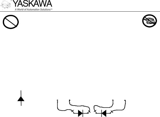
Input Diodes
Certain GPD 506/P5 inverters come equipped with a 12 pulse, dual diode input section. This leads to a reduction of the input current distortion to help meet harmonic distortion specifications. The schematic diagrams of a dual diode input and a 6 pulse diode input are shown below.
Diode configuration for 12 pulse input used in GPD 506/P5 inverters.
-
Diode configuration for 6 pulse input used in GPD 515/G5 inverters.
PP.P5G5.01.Troubleshoot
Page 13
Rev. 06/11/2003
Input Diodes
The individual diodes that form the three-phase input rectifier bridge can easily be checked by measuring the forward and reverse resistance of the diodes. Simply use an analog or digital meter and measure the resistance across each diode. Refer to the elementary diagram to determine the relationship between the main input terminals (L1, L2, L3) and the DC bus terminals. By checking the resistance from each input terminal to the positive bus and the negative bus (then swapping your meter leads) you can check each of the diodes. Remember, you should see a resistance reading typical of a diode, with low resistance in one direction and fairly high resistance after you swap the meter leads.
Cathode (-) |
|
|
|
|
|
|
|
|
|
||
|
|
|
|
|
|
|
|
|
|||
|
0.5 |
|
|
|
|
OL |
|
|
|||
|
|
|
|
|
|
|
|
|
|
||
|
|
|
|
DVM |
_ |
|
|
|
|
|
|
|
|
|
|
|
|
DVM |
_ |
||||
|
|
|
+ |
|
|
|
+ |
|
|
||
Anode (+)
Resistance Readings
PP.P5G5.01.Troubleshoot
Page 14
Rev. 06/11/2003
 Loading...