


Product Transition Guide
GPD 506/P5 to P7
PL.P7.06.TransitionP5

Product Transition Guide
GPD506/P5 to P7
NOTICE
The information contained within this document is the proprietary property of Yaskawa Electric America, Inc., and may not be copied, reproduced or transmitted to other parties without the expressed written authorization of Yaskawa Electric America, Inc. No patent liability is assumed with respect to the use of the information contained herein. Moreover, because Yaskawa is constantly improving its high-quality products, the information contained in this document is subject to change without notice. Every precaution has been taken in the preparation of this document. Nevertheless, Yaskawa assumes no responsibility for errors or omissions. Neither is any liability assumed for damages resulting from the use of the information contained in this publication.
Page 2 of 48

Product Transition Guide |
|
GPD506/P5 to P7 |
|
Contents |
|
FEATURE OVERVIEW ........................................................................................ |
5 |
BENEFITS OF THE NEW P7 WHEN COMPARED TO GPD506/P5 ................... |
5 |
NEW/ADDITIONAL P7 PARAMETER FUNCTIONS NOT PRESENT IN THE GPD506/P5 ...................... |
5 |
P7 DIGITAL INPUTS (ADDITIONAL FUNCTIONS)............................................................................. |
6 |
P7 DIGITAL INPUTS (ADDITIONAL FUNCTIONS)............................................................................. |
6 |
P7 ANALOG INPUT (ADDITIONAL FUNCTIONS) .............................................................................. |
6 |
P7 DIGITAL OUTPUT RELAY (ADDITIONAL FUNCTIONS)................................................................. |
6 |
P7 ANALOG OUTPUTS (ADDITIONAL FUNCTIONS)......................................................................... |
6 |
P7 SERIAL COMMUNICATIONS .................................................................................................... |
7 |
P7 START-UP, INSTALLATION & MAINTENANCE IMPROVEMENTS.................................................... |
7 |
P7 ADDITIONAL HARDWARE PROTECTION ................................................................................... |
7 |
REASONS TO CONTINUE GPD506/P5 ........................................................................................ |
7 |
GPD506/P5 TO P7 SPECIFICATION DIFFERENCES ........................................ |
9 |
DIGITAL OPERATOR COMPARISON .............................................................. |
12 |
GPD506/P5 TO P7 TERMINAL COMPARISON................................................ |
13 |
NETWORK COMMUNICATIONS ...................................................................... |
17 |
DETAILS ON NEW P7 FEATURES & FUNCTIONS ......................................... |
18 |
APPENDIX 1 ...................................................................................................... |
19 |
RATINGS AND HEAT LOSS COMPARISON ................................................................................... |
19 |
NEC HP RATINGS FOR 240V NORMAL DUTY MODELS .............................................................. |
21 |
NEC HP RATINGS FOR 480V NORMAL DUTY MODELS .............................................................. |
22 |
HEAT LOSS DATA.................................................................................................................... |
23 |
APPENDIX 2 ...................................................................................................... |
25 |
MECHANICAL DIMENSIONS ....................................................................................................... |
25 |
PANEL CUT-OUT FOR EXTERNAL HEATSINK MOUNTING .............................................................. |
27 |
MOUNTING HOLE DATA............................................................................................................ |
28 |
APPENDIX 3 – PARAMETER CROSS REFERENCE....................................... |
29 |
Page 3 of 48

Product Transition Guide
GPD506/P5 to P7
Page Intentionally Left Blank
Page 4 of 48
Product Transition Guide
GPD506/P5 to P7
Feature Overview
This document details differences between the GPD506/P5 and P7 product to assist in product transition and new product introduction.
GPD506/P5 Drive
The GPD 506/P5 inverter is intended for fan and pump applications in Building and Industrial Automation. It is available in constant and variable torque ratings, 3/4 to 500 horsepower.
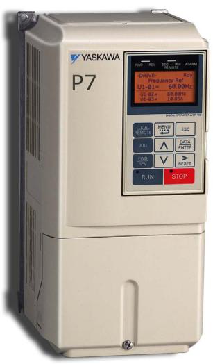
P7 Drive
The P7 drive is an ideal choice for industrial applications, such as centrifugal fans and pumps. The P7 drive is provided in Normal Duty ratings with 110% overload capability. V/f control mode, network communication options, and an array of input/output choices are available.
Benefits of the New P7 When Compared to GPD506/P5
New/Additional P7 Parameter Functions not Present in the GPD506/P5
New Motor preheat function with adjustable current setting to prevent condensation in motor, (b2-09)
P7 is flash memory upgradeable
Accel/Decel range now adjustable from 0.1 to 6000 sec. (GPD506/P5 max. range is 3600)
Critical frequency rejection: 3 selectable, adjustable bands, d3-03—Jump frequency 3 (additional) (GPD506/P5 only has two)
New Wait To Run Timer function allowing output of drive to delay start after a Run command (b1-11)
Torque boost with adjustable filter time for better torque compensation response (C4-02)
Power loss ride-thru time settable to 25 sec. (GPD506/P5 is 2 sec. Max.)
Auto restart now has maximum restart time after fault if fault condition doesn’t clear during the first try
New "Up/Down" floating point control capability Primary resistance auto-tuning
Customizable monitor display Run permissive input
New PI Snooze function available in conjunction with Sleep mode (b5-21)
Adjustable Undervoltage Detection level (L2-05) not available in GPD506/P5
Speed search function with new Speed Estimation mode and Bi-directional search mode (b3-01)
New Setpoint PI features include:
Two feedback capability, Output Limit, Offset adjustment, Primary delay, Output gain, Output reverse, Setpoint accel/decel, Setpoint display scaling, Selectable sleep input source, Snooze function, Setpoint boost, Fdbk square root function with output monitor. (b5-06, b5-07, b5-08, b5-10, b5-11, b5-17 thru 30)
Separately adjustable e-stop times (C1-09)
Accel/decel rate switchover via output frequency (C111)
14 more V/f presets than GPD506/P5 for a total of 15 V/f preset patterns (E1-03)
Mid frequency and voltage V/f points on the custom V/f pattern (E1-11,12)
Trim speed control function (d4-02)
New/Additional P7 Parameter Functions not Present in the GPD506/P5
Page 5 of 48

Product Transition Guide GPD506/P5 to P7
Motor thermistor input with temperature filter and selectable fault ,alarm settings (L1-02 to L105)
Intelligent stall prevention on accel/decel with decel time 1 or 2 selections (L3-01,4,5)
Extended 0.5 to 600.0 sec. autorestart time between attempts vs. 10.0 secs for GPD506/P5 (L5-03)
Hunting prevention function (n101,2)
DC Injection braking (b1-03)
Run command can be accepted while the drive is being programmed (b1-08)
High slip braking function (n3-01,2,3,4) Selectable power-up monitor (o1-01,2) Keypad display contrast adjustment (o1-05)
Two independent programmable over and under torque detection levels
P7 Digital Inputs (Additional Functions)
One more digital input for a total of seven
More versatile PNP/NPN sinking/sourcing 24 VDC control logic
Transmitter/option power supply
29 more programmable functions for digital inputs than GPD506/P5. 59 total :
Motor Preheat
MOP increase/decrease function Forward and reverse jog input
Trim control increase and decrease functions
15 additional external fault action settings such as Faststop, Alarm only, Coast to stop with selectable N.O or N.C. for each fault action.
PI integral hold and PI cancel functions Speed search 3
Serial Communication test mode High slip braking input
Jog 2
P7 Analog Input (Additional Functions)
A convenient PCB switch now changes analog input A2 between current and voltage, cutting PCB jumper for mA signal is no longer required.
Adjustable analog input signal filter for added stability Terminal A2 is selectable for :
Frequency bias Motor thermister PI differential Analog input filter
Main and Aux frequency reference is selectable between terminals A1 and A2
P7 Digital Output Relay (Additional Functions)
27 possible programmable functions for the digital outputs, seven more than the GPD506/P5.
One additional relay output, M3 and M4 relays DC bus under voltage output
Reset command active output Reverse direction output Drive enable output
OH frequency reduction output Restart Enabled
P7 Analog Outputs (Additional Functions)
Additional AM analog monitor output with bias and gain settings.
Analog monitors now selectable between 0-10V and 4- 20ma, GPD506/P5 only 0-10V
18 programmable selections for the analog outputs, 14 more than the GPD506/P5.
Frequency reference monitor Terminal A1 or A2 monitor Motor SEC current monitor SFS output monitor
PIfeedback, input, output and setpoint monitors PI feedback 2 monitor
Output Voltage
P7 Digital Inputs (Additional Functions)
Drive enable, with selectable accept run command or cycle run command function
Page 6 of 48
Product Transition Guide
GPD506/P5 to P7
P7 Serial Communications
Built-in RS-485/422 modbus serial communications
Optional communication interface: Devicenet, Profibus, and others
Serial communications loss detection timeout function
Drive Wizard upload/download and monitoring /graphing software
P7 Start-up, Installation & Maintenance Improvements
Control terminal board: Quick disconnect
Enhanced digital keypad, 5 Line x 16 Character LCD (Std)
6 new languages can be displayed on the keypad. GPD506/P5 has only English (A1-00)
User password protection for 32 customizable user parameters (A1-04)
A2-01 thru A2-32—User access level provides 32 user selectable parameters.
Parameter copy function to another P7 using standard digital operator (o3-01)
Improved fault storage, last 10 faults Quick disconnect I/O blocks for easy wiring
Logged cooling fan hours for scheduled maintenance Modular cooling fan for easy replacement Automatic cooling fan run control to extend fan life
P7 Additional Hardware Protection
Adjustable heat-sink overheat pre-alarm level (L8-02) Selectable ground fault detection (L8-09)
Selectable cooling fan operation with off delay (L810,11)
Automatic ambient temperature compensation to protect the drive in environments exceeding its rating (L8-12)
Adjustable OH frequency reference reduction (L8-19) Adjustable motor overload time constant (L1-02)
Page 7 of 48
Product Transition Guide
GPD506/P5 to P7
Page left intentionally blank
Page 8 of 48

Product Transition Guide
GPD506/P5 to P7
GPD506/P5 to P7 Specification Differences
Feature |
Item |
Yaskawa GPD506/P5 |
Yaskawa P7 |
|
or Function |
|
|
|
|
Performance Features |
|
|
||
|
|
|
|
|
HP Range |
|
240V |
0.75 to 125HP (VT) |
5 to 150HP (ND2) |
|
|
|
|
|
Note: The voltage rating in |
|
480V |
0.75 to 500HP (VT) |
5 to 500HP (ND2) |
|
|
|
|
|
the “Item” column is |
|
|
|
|
generalized. Refer to the |
|
600V |
2 to 200HP (VT) |
Available w/GPD506/P5 |
Service Conditions section |
|
|||
|
Not Available in P7 |
|||
for rated input voltage |
|
|
|
|
|
|
|
|
|
requirements. |
|
|
|
|
Overload Rating |
|
|
150% for 1 min (CT) |
|
|
|
|
|
|
|
% for Minutes |
200% peak |
110% for 1 min (ND2) |
|
|
120% for 1 min (VT) |
150% peak |
||
|
|
|
||
|
|
|
180% peak |
|
|
|
|
|
|
PWM Carrier Frequency |
|
Range |
See Carrier Frequency Table |
See Carrier Frequency Table |
|
|
|||
|
|
|
|
|
Max. Output Frequency |
|
Hz |
400Hz |
0 To 120Hz |
|
|
|||
|
|
|
|
|
Speed Range |
|
V/f |
40:1 |
40:1 |
|
|
|||
|
|
|
|
|
Protective Features |
|
|
|
|
|
|
|
|
|
Heat Sink Temperature Fault |
|
|
|
--Coast, Ramp, Continue or |
|
|
|
|
|
|
Fault Action |
Coast, Ramp, Continue |
Continue with reduced speed |
|
|
|
|
|
--OH Pre-alarm level setting |
|
|
|
|
|
Design Features |
|
|
|
|
|
|
|
|
|
Keypad Design |
Qty of keys |
7 |
11 |
|
|
|
|
|
|
|
Language |
1 |
7 (w/LCD) |
|
|
Copy Function |
No |
Yes |
|
|
|
|||
|
|
|
|
|
|
|
Display |
LCD display, alpha numeric, 16 |
LCD display, alpha numeric, 16 |
|
|
char x 2 lines |
char x 5 lines, backlit |
|
|
|
|
||
|
|
|
|
|
|
|
|
|
|
Page 9 of 48

Product Transition Guide
GPD506/P5 to P7
GPD506/P5 to P7 Specification Differences (continued)
Feature |
Item |
Yaskawa GPD506/P5 |
|
or Function |
|
|
|
|
|
|
|
Design Features (continued)
Network Communications |
Standard |
Modbus RTU via RS232 |
|
||
|
|
|
|
|
RS232 to RS485, DeviceNet, |
|
Optional |
Lonworks, ApogeeFLN, |
|
|
MetasysN2 |
Diagnostics |
|
|
|
Fault Storage |
Last 4 Faults |
|
|
|
Quick Disconnect I/O |
Type |
No |
Terminals |
||
|
|
|
Auto-Tuning |
Rotating/Stationary |
No |
|
||
|
|
|
Speed Search |
Bi/Uni-Directional |
Uni-Directional |
Synchronized Start |
Method |
Current |
PI / PID Control |
Analog Input Signal |
No |
|
Filter |
|
|
|
|
|
Two Feedback |
No |
Sleep Function |
In Open Loop Mode |
No |
Automatic Restart |
Time Between |
Not Adjustable |
|
Attempts |
|
|
|
|
V/Hz Patterns |
Qty. |
1 Preset, 1 Custom |
Skip Frequencies |
Qty. |
2 |
Custom Drive Software |
Embedded |
No |
Parameter Upload/Download |
PC Software |
InverterWin |
Accel/Decel Time |
Sec. |
0.0 - 3600.0 sec |
Closed Loop PID Control |
Analog Input Filter |
No |
|
Two Feedback |
No |
DC Injection Function |
At Start/At Stop |
At Start/At Stop |
|
||
|
|
|
Braking Function |
DB Transistor |
Built-in to 10HP (VT-230V) |
|
Built-in to 25HP (VT-460V) |
|
|
|
|
|
Special |
No |
|
|
|
Cooling Fan |
On/Off Control |
Power-up based |
|
Service |
Disassembly required |
|
|
|
|
Operating Hours |
Drive power-up hours logged |
Timer Function |
On/Off Delay |
On/Off Delay (0-25.5 sec) |
|
||
|
|
|
Modbus RTU via built in RS485/422
DeviceNet, Profibus-DP,
Lonworks,
Ethernet
Last 10 Faults with Elapsed Time, Most Recent Fault with all Operating Conditions
Yes (Phoenix)
With split front cover for easy wiring
Primary resistance auto-tuning
Bi-Directional
Current/Speed
Yes
Yes
Yes
0.0 – 600.0 sec (selectable)
15 Preset, 2 Custom
3
Flash memory
Drive Wizard Software
0.1 - 6000.0 sec.
Yes
Yes
At Start/At Stop (adjustable)
+HSB during stop
Built-in to 25HP
High Slip Braking all models (Faster stopping without options)
Run Based
Modular/pluggable fan select models
Logged
On Delay at start (0-600 sec) On/Off Delay Timer ( 0-3000sec)
Page 10 of 48
Product Transition Guide
GPD506/P5 to P7
GPD506/P5 to P7 Specification Differences (continued)
Feature |
Item |
|
Yaskawa GPD506/P5 |
|
or Function
Design Features (continued)
Common DC Bus Capable |
- |
No |
DC Link or AC Choke |
- |
230V: 30HP to 125HP (VT) |
|
||
|
460V: 30 to 250HP (VT) |
|
|
|
|
|
|
|
Harmonic Counter Measures |
- |
12 Pulse: 230V: 30HP and Above |
|
||
|
460V: 30HP to 250HP |
|
|
|
|
|
|
|
Unique Feature/Function |
- |
- |
Inputs and Outputs |
|
|
Digital Input Terminal |
Total Qty. |
6 |
|
NPN/PNP |
NPN |
Digital Output Terminal |
Total Qty |
2 |
|
Relay Output |
1 x Form C, 1 x Form A, |
Analog Input |
Qty. |
2 |
|
Level Input |
0-10V or 4-20mA |
|
Scan Rate |
5 msec |
|
Loss Detection |
Ramp or Continue |
Analog Output |
Qty. |
1 |
|
Output Level |
0-10V |
|
|
|
|
Resolution |
9 bit |
Service Conditions |
|
|
Rated Input |
|
3-phase, 200-230Vac |
|
|
3-phase, 380-460Vac |
|
- |
Tolerance +10 to –15% |
|
3-phase,500-600Vac |
|
|
|
|
|
|
Tolerance +10 to –10% |
|
|
Frequency: 50/60 Hz +/- 5% |
Ambient Temperature |
|
(IP21/NEMA1) |
|
|
|
|
ºC |
-10ºC ~ +40ºC |
|
(IP00/Protected Chassis) |
|
|
|
|
|
|
-10ºC ~ +45ºC |
|
|
|
Storage Temperature |
ºC |
-10ºC ~ +60ºC |
Enclosure Types |
NEMA 4X |
Optional |
|
NEMA 3/3R |
Optional |
Yes
DC Link (Standard) 240V: 30HP to 150 HP 480V: 40 HP to 500 HP
12 Pulse: 240V: 30HP to 150HP 480V: 40HP to 500HP
HSB – High Slip Braking
7 (optically isolated) Switchable NPN/PNP 3
2 x Form A, 1 x Form C
2
0-10 or 4-20mA
5 msec
Ramp, Coast or Continue 2
0-10V or 4-20ma
With independent level selections 10 bit plus sign
3-phase, 200-240Vac
3-phase, 380-480Vac Tolerance +10 to –15% Frequency: 50/60 Hz +/- 5% Note: P7 Models 2037-2110 rated for 200-230Vac.
-10ºC ~ +40ºC (IP21/NEMA1) -10ºC ~ +45ºC (IP00/Protected Chassis) (Automatic OL protection curve based on ambient temperature setting of L8-12)
-20ºC ~ +60ºC N/A N/A
Page 11 of 48
Product Transition Guide
GPD506/P5 to P7
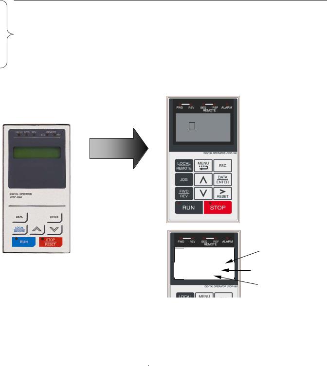
Digital Operator Comparison
•Enhanced LCD operator with built-in copy function and parameter verify for P7
•Optional LED operator available for P7
•LCD contrast adjustment
•Simplified parameter grouping for easier navigation and set-up
GPD506/P5 Operator |
New P7 Operator |
LCD DISPLAY |
Menu Display |
|
|
|
|
|
Frequency Ref |
||||
|
|
-DRIVE- |
Rdy |
||
|
|
|
|
||
|
|
U1- |
01 |
= |
60.00Hz |
|
|
- - - - - - - - - - |
- - - - - - - - - - - - - - - - - - - |
||
|
|
U1-02= |
60.00Hz |
||
|
|
U1-03= |
10.05A |
||
Frequency Ref
U1-01 = 0.00Hz
Drive Mode Indicators
Ready Display
Drive can operate when a drive command is input
Data Display
Displays monitor data, parameter data and settings 1 line x 13 characters
3 lines x 16 characters
Keys
|
RUN & STOP Indicators |
|
-QUICK- Accel Time 1 -Rdy- |
Present Setting |
|
(user adjusts) |
||
------------------------------ |
||
C1-01= 21.0secs |
Allowed Setting Range |
|
(0.0~6000.0) |
||
“30.0 sec” |
|
|
|
Factory Default |
•P7 copy keypad is capable of uploading all of the parameter settings from the P7 drive memory. o Upload of GPD506/P5 parameters to P7 not possible at this time
o P7 Drives must have the same software version, model, and control mode to copy parameters.
•A Quick Start menu is added to aid in simple start-ups.
•The Quick Start menu consists of 64 parameters. The Advanced menu is the other menu choice.
Simplified Menu Structure in P7:
GPD506/P5 |
|
P7 |
-- |
|
Operation “DRIVE” |
Quick Start -- 16 Parameters |
|
Quick Setting “QUICK” |
Programming (All Parameters) |
|
Programming “ADV” |
-- |
|
Modified Constants “VERIFY” |
-- |
|
Auto-Tuning “A.TUNE” |
-- |
|
|
|
Page 12 of 48 |
|

Product Transition Guide
GPD506/P5 to P7
GPD506/P5 to P7 Terminal Comparison
The factory default is 2-wire control as shown.
Type
Digital Input Signals
GPD506/P5 Terminal |
|
P7 Terminal |
|||
|
(Designations similar to GPD506/P5) |
||||
|
|
|
|||
GPD506/P5 |
Default Function & Description |
P7 |
Default Function |
P7 Description |
|
Terminal |
|
Terminal |
|||
|
|
|
|||
|
Forward run/stop, Forward run |
|
|
|
|
S1 |
when closed, and stop when |
S1 |
|
|
|
open. |
Forward run/stop command |
– |
|||
|
Photo-coupler insulation |
|
|
|
|
|
Input: +24VDC 8mA |
|
|
|
|
|
Reverse run/stop, Reverse run |
|
|
|
|
|
when closed, Stop when open. |
|
|
|
|
S2 |
Multi-function contact |
S2 |
Reverse run/stop command |
– |
|
input (n036) |
|||||
|
|
|
|
||
|
Photo-coupler insulation |
|
|
|
|
|
Input: +24VDC 8mA |
|
|
|
|
|
External fault input, Fault when |
|
|
|
|
|
closed, normal state when open. |
|
|
|
|
S3 |
Multi-function contact input |
S3 |
External fault input |
|
|
(n037) |
|
||||
|
|
|
|
||
|
Photo-coupler insulation |
|
|
|
|
|
Input: +24VDC 8mA |
|
|
|
|
|
Fault reset input, |
|
|
Multi-function digital inputs. |
|
|
Reset when closed. |
|
|
|
|
S4 |
Multi-function contact input |
S4 |
Fault reset |
Functions set by: |
|
(n038) |
H1-01 to H1-05. |
||||
|
|
|
|||
|
Photo-coupler insulation |
|
|
24 VDC, 8mA |
|
|
Input: +24VDC 8mA |
|
|
Photo coupler isolation |
|
|
Multi-step speed reference 1, |
|
|
|
|
|
Enabled when closed. |
|
|
|
|
S5 |
Multi-function contact input |
S5 |
Multi-step speed reference 1 |
|
|
(n039) |
|
|
|||
|
|
|
|
||
|
Photo-coupler insulation |
|
|
|
|
|
Input: +24VDC 8mA |
|
|
|
|
|
Multi-step speed reference 2, |
|
|
|
|
|
Enabled when closed. |
|
|
|
|
S6 |
Multi-function contact input |
S6 |
Multi-step speed reference 2 |
|
|
(n040) |
|
||||
|
|
|
|
||
|
Photo-coupler insulation |
|
|
|
|
|
Input: +24VDC 8mA |
|
|
|
|
– |
– |
S7 |
Jog frequency reference |
|
|
SC |
Sequence input common |
SN |
Digital input common |
Factory connected for internal |
|
terminal |
|||||
|
|
|
supply sinking mode. |
||
|
– |
|
|
||
|
SC |
Factory connected to SP |
Refer to P7 User Manual for |
||
|
|
||||
|
|
|
|
other methods. |
|
|
– |
SP |
Factory connected to SC |
||
|
|
||||
Page 13 of 48

Product Transition Guide GPD506/P5 to P7
Type
Analog Input Signals
Digital Output Signals
Signals
Analog Output
GPD506/P5 Terminal |
|
P7 Terminal |
|||
|
(Designations similar to GPD506/P5) |
||||
|
|
|
|||
GPD506/P5 |
Default Function & Description |
P7 |
Default Function |
P7 Description |
|
Terminal |
|
Terminal |
|||
|
|
|
|||
FS |
+15V Power supply output for |
+V |
+15Vdc power output |
+15Vdc |
|
analog command |
|||||
(Max. current: 20mA) |
|||||
|
(Allowable current, 20mA max.) |
|
|
||
|
|
|
|
||
|
Frequency reference input |
|
|
|
|
|
(voltage) 0 to +10V/100%, |
|
|
|
|
FV |
n043 = “FV=MSTR”: |
A1 |
Analog input or speed |
0 to +10Vdc=100% |
|
FV enabled |
|||||
command |
(20k ohm) |
||||
|
n043 = “FI=MSTR”: |
|
|||
|
|
|
|
||
|
FI enabled |
|
|
|
|
|
0 to +10V (20kW) |
|
|
|
|
|
Frequency reference input |
|
|
|
|
|
(current) 4 to 20mA/100% |
|
|
|
|
FI |
n043 = “FV=MSTR”: |
A2 |
Analog input or speed |
4 to 20mA=100%/(250 ohms) |
|
FV enabled |
0 to +10Vdc=100%/(20k ohm) |
||||
command |
|||||
|
n043 = “FI=MSTR”: |
|
Function set by H3-09. |
||
|
|
|
|||
|
FI enabled |
|
|
|
|
|
4 to 20mA (250W) |
|
|
|
|
FC |
Common terminal 0V |
AC |
Analog common |
– |
|
|
|||||
|
|
|
|
|
|
E(G) |
Connection to shield sheath of |
E(G) |
Shield wire, optional ground |
– |
|
signal lead |
line connection point |
||||
M1 |
During running (N.O. contact) |
M1 |
|
Form A Dry contacts capacity: |
|
Closed when running. |
|
||||
|
|
|
|||
|
Multi-function contact output |
|
During run |
1 A max. at 250Vac |
|
|
|
||||
|
(n042) |
|
1 A max. at 30Vdc |
||
|
|
(N.O. contact) |
|||
M2 |
Dry contact capacity: |
M2 |
Multi-function digital output. |
||
|
|||||
|
250VAC 1A or less |
|
|
Function set by H2-01. |
|
|
30VDC 1A or less |
|
|
|
|
|
– |
|
|
Form A Dry contacts capacity: |
|
– |
|
M3 |
Remote/Auto Operation |
1 A max. at 250Vac |
|
|
|
|
1 A max. at 30Vdc |
||
|
|
|
(N.O. contact) |
||
|
|
|
Multi-function digital output. |
||
– |
– |
M4 |
|||
|
|||||
|
Function set by H2-02. |
||||
|
|
||||
|
|
|
|
||
MA |
Fault contact output |
MA |
|
|
|
|
(N.O./N.C. contact) |
|
|
|
|
MB |
MB |
|
|
||
Fault when closed between |
|
|
|||
|
|
|
|
||
|
terminals MA and MC |
|
Same function as |
Form C Dry contacts |
|
|
Fault when open between |
|
|||
|
|
GPD506/P5. Non- |
capacity: |
||
|
terminals MB and MC |
|
|||
|
|
programmable |
1 A max. at 250Vac |
||
MC |
Multi-function contact output |
MC |
|||
|
1 A max. at 30Vdc |
||||
(n041) |
|
||||
|
|
|
|
||
|
Dry contact capacity: |
|
|
|
|
|
250VAC 1A or less |
|
|
|
|
|
30VDC 1A or less |
|
|
|
|
|
Frequency meter output |
|
|
|
|
|
0 to +10V/100% frequency |
|
|
0 to +10Vdc |
|
|
Multi-function analog monitor 1 |
|
|
||
|
|
|
10V=100% Output frequency |
||
AM |
(n052) |
FM |
Output frequency |
||
(Max current 2mA). |
|||||
|
0 to +10V |
|
|
||
|
|
|
Function set by H4-01. |
||
|
2mA or less |
|
|
||
|
|
|
|
||
|
|
|
|
|
|
Page 14 of 48

Product Transition Guide
Terminal Comparison
|
GPD506/P5 Terminal |
|
P7 Terminal |
||
|
|
(Designations similar to GPD506/P5) |
|||
|
|
|
|
||
Type |
GPD506/P5 |
Default Function & Description |
P7 |
Default Function |
P7 Description |
|
|||||
|
Terminal |
|
Terminal |
|
|
|
|
– |
|
|
0 to +10Vdc or |
|
|
|
AM |
|
10V=100% Drive output |
|
– |
|
Output current |
current (Max current 2mA) |
|
|
|
|
|
|
Drive's rated output current / |
|
|
|
|
|
Function set by H4-04. |
|
AC |
Frequency meter output “AM” |
AC |
Analog common |
– |
|
Common |
||||
|
|
|
|
|
|
|
– |
– |
R+ |
Modbus communication |
|
|
|
|
|
Differential input, |
|
485/422 |
– |
– |
R- |
|
|
PHC isolation |
|
||||
|
– |
||||
|
|
||||
|
|
|
|
||
|
– |
– |
S+ |
Modbus communication |
|
|
|
||||
RS- |
|
|
|
Differential output, |
|
– |
– |
S- |
|
||
PHC isolation |
|
||||
|
|
|
|
|
|
|
– |
– |
IG |
Signal common |
– |
Page 15 of 48
 Loading...